 |
Functional Enhancements |
| <<< Using Parasolid | Chapters | Interface Changes >>> |
This chapter describes the functional enhancements that have been added to the current release of Parasolid.
|
Note: For detailed information on interface changes see Chapter 7, "Interface Changes". |
You can now identify any constant radius blend faces in a supplied array of faces, together with their radii and convexities.
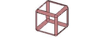
Figure 6-1 Identifying constant radius blends in a set of faces
For more information, see Chapter 40, "Simplifying Models", of the Functional Description.
You can now divide a given body into facesets bounded by a set of supplied edges. A variety of options are available to let you return all facesets, only those that contain a set of supplied topologies, only those that exclude topologies, or alternating facesets.
For more information, see Chapter 40, "Simplifying Models", of the Functional Description.
New functionality has been added that you can use to aid simplification of bodies.
It is now possible to return facesets in a body that are recognized as particular types of detail (e.g. holes), and you can delete specifed facesets from a given body. Used in conjunction, it is now possible to identify and remove particular details from a body in a robust manner.
For more information, see Chapter 40, "Simplifying Models", of the Functional Description.
Parasolid's tapering functionality has been extended to provide single and double-sided tapering of a body. This specialized functionality lets you design parted molds in a single step.
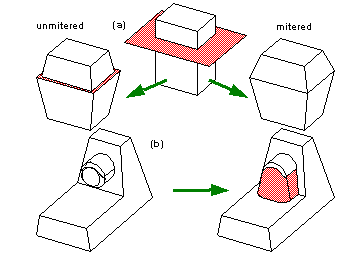
Figure 6-2 Performing (a) double-sided and (b) single-sided tapering on a body
For more information, see Chapter 21, "Local Ops: Double-Sided Tapering", of the Functional Description.
Previously, it was not possible to cap an edge blend if the edges that were extended to cap the blend intersected. This restriction has now been removed.
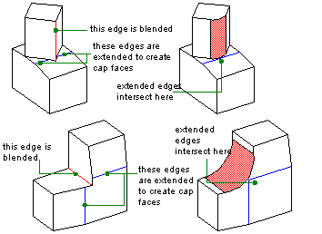
Figure 6-3 Capping edge blends where edges extended to form cap intersect
This functionality can be switched off using the
update
control in PK_BODY_fix_blends. For more information, see Chapter 30, "Edge Blending Functions and Options", of the Functional Description.
Parasolid can now generate faces to fill a hole in a sheet body. Previously your application was required to supply a suitable sheet body. When Parasolid generates a patch, the boundary of the hole is maintained, and the filling geometry meets the surrounding faces on the hole smoothly.

Figure 6-4 Generating a patch to fill a hole
For more information, see Chapter 16, "Local Ops: Creating Surfaces to Attach to Faces", of the Functional Description.
Derivative constraints can now be applied to guide wires and intermediate profiles when constructing a lofted body. Previously, derivative constraints could only be applied to loft profiles.

Figure 6-5 Applying derivative constraints to guide wires during lofting
For more information, see Chapter 27, "Advanced Surfacing", of the Functional Description.
Parasolid's functionality for creating Y-shaped blends has been extended. You can now create two Y-shaped blends that meet at a vertex. Any intermediate edges between the blends must be smooth for the blends to be successful. Additionally, you can now apply a Y shaped blend in cases where two edges forming a Y-blend do not meet smoothly, providing that there is a second Y-blend at the same vertex.
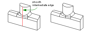
Figure 6-6 Creating two Y-shaped blends at a vertex
For more information, see Chapter 30, "Edge Blending Functions and Options", of the Functional Description.
Parasolid's face-face blending functionality has been improved as follows:
For more information, see Chapter 33, "Face-Face Blending", of the Functional Description.
When regenerating blends as part of a face change operation, you can now specify the radius of the blend when it is reapplied. If no blend radius is specified then the blend radius of the original blend is used when the blend is reapplied.
For more information, see Chapter 23, "Local Ops: Generic Face Editing", of the Functional Description.
Parasolid has enhanced its support for replacing the surfaces of faces.
You can now replace the surfaces of several faces with a single replacement surface by passing the replacement surface to Parasolid once. Previously, you needed to pass the replacement surface several times: once for each face being replaced.
You can now control how adjacent faces are merged after replace face operations, in cases where the faces become mergable, as shown in Figure 6-7.

Figure 6-7 Controlling merging of faces during replace face operations
No merging is performed for edges for which replacement curves have been provided. Merging is recommended when adjacent faces are to acquire identical surfaces.
For more information, see Chapter 17, "Local Ops: Tweaking the Surfaces of Faces", and Chapter 23, "Local Ops: Generic Face Editing", of the Functional Description.
Parasolid can now automatically create offset step faces along smooth boundaries between offset and non-offset faces in a body.
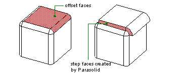
Figure 6-8 Creating step faces during offsetting
For more information, see Chapter 19, "Local Ops: Hollowing & Offsetting", of the Functional Description.
When sweeping, you can now remove undesirable twists from the swept body. This is done by ignoring regions of the specified path with rapidly changing curvature.
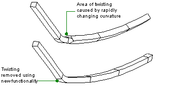
Figure 6-9 Removing undesirable twisting in sweep operations
For more information, see Chapter 27, "Advanced Surfacing", of the Functional Description.
Detection of clashing topology has been improved. Previously, it was only possible to detect clashes between two sets of bodies. It is now possible to detect clashes between bodies, faces, or both.
For more information, see Chapter 9, "Boolean Operations", of the Functional Description.
You can now simplify the B-geometry for a supplied list of faces and their edges. Previously, it was only possible to simplify the B-geometry of an entire body.
For more information, see Chapter 40, "Simplifying Models", of the Functional Description.
When sewing sheet bodies together, you can now request that sheets are removed if they are duplicates to within the specified gap width bound of the sewing operation.
For more information, see Chapter 36, "Sheet Sewing", of the Functional Description.
When rendering edges, you can now specify an angle of tolerance, within which faces on either side of the rendered edge are considered smooth.
For more information, see Chapter 53, "Rendering Option Settings", of the Functional Description.
You can now control which of two coincident edges survives in a boolean or section operation.
For more information, see Chapter 9, "Boolean Operations", and Chapter 11, "Sectioning", of the Functional Description.
Previously, curves that were already attached to edges, fins or nominal geometry, were shared whenever possible. Attaching the curve failed if this sharing was not possible. This behavour has now changed, so that if sharing is not possible a copy of the curve is made and attached to the edge.
When creating wire bodies using curves from several different partitions, any input curves in a partition other than the current partition are duplicated. The resultant body is in the current partition.
You can now use multiple viewports with PK_TOPOL_render_line. The existing single viewport functionality remains unchanged. An extra option is available to let you specify an array of multiple viewports.
For more information, see Chapter 53, "Rendering Option Settings", of the Functional Description.
When a facet vertex occurs at a degeneracy, the value of the degenerate parameter at the degenerate vertex can now be calculated from the average of the values of that parameter at the two facet vertices at the other ends of the facet edges which meet at the degenerate vertex. The normals and derivatives at the degenerate vertex are evaluated using this average value for the degenerate parameter.
For more information, see Chapter 54, "Facet Mesh Generation", of the Functional Description.
You can now specify that change events to bodies should appear on the bulletin board. If this is specified, then the first change to a body after the bulletin board was created or emptied results in a change event on the bulletin board.
For more information, see Chapter 57, "Bulletin Board", of the Functional Description.
Parasolid now supports part keys in 16-bit Unicode form as well as the native character set. To preserve runtime compatibility with older applications, the extra fields in various Frustrum structures must be explicitly enabled via PK_SESSION_set_unicode; otherwise the fields are ignored and the appropriate receive/transmit functions will fail.
For more information, see the Downward Interfaces manual, in particular, Chapter 2, "File Handling", Appendix A, "Frustrum Functions", and Appendix E, "Application I/O Functions".
|
Note: Your application code must be fully re-compiled if you wish to make use of Unicode functionality. |
To support the Parasolid eXT schemas, you can now transmit text versions of parts, partitions, and sessions with character data translated into a format suitable for embedding in XML files. This format escapes the "<" and "&" characters.
For more information, see Chapter 42, "Archives", of the Functional Description.
You can now configure and enquire about the minimum amount of contiguous memory space that Parasolid requests for modeling operations. This can be done at any point - even when the modeler is not running. You can also reset the default smallest block size at any time. When the modeler is stopped the smallest block size is always returned to Parasolid's default block size.
For more information, see Chapter 58, "Session Support", of the Functional Description.
This section includes miscellaneous issues that are not covered elsewhere in this chapter.
The Pentium 4 version of Parasolid V13.0 FCS was built using a beta-release compiler, and is therefore a beta release. A version built using a production-release compiler will be made available in a later patch release.
SMP is currently switched off in the Pentium 4 version of Parasolid V13.0.
SMP is currently switched off in the 64-bit version of Parasolid V13.0.
| <<< Using Parasolid | Chapters | Interface Changes >>> |