 |
Local Ops: Hollowing & Offsetting |

Local Ops: Hollowing & Offsetting
| <<< Local Ops: Transforming Faces | Chapters | Local Ops: Adding Draft >>> |
Hollowing and offsetting are used to model, for example, objects for injection molding or casting, or thin walled aerodynamic parts. Parasolid does not allow total freedom of topology changes but does support a wide spectrum of permissible changes, which were discussed in Section 12.2.1, "Classes of topology change".
Solid bodies are hollowed in Parasolid using either of the following functions:
PK_FACE_hollow_3 is described in Section 19.2.2, "Offsetting specific faces in a body". The rest of this section describes the more commonly used PK_BODY_hollow_2.
The commonest way to hollow a body is to use PK_BODY_hollow_2. This function takes the following arguments:
| Argument | Description |
|---|---|
|
Under some circumstances it may be necessary to replace exact edge geometry with tolerant geometry. Parasolid uses the supplied tolerance when calculating approximate geometry. |
All the faces in that body are then offset by the given offset, creating a hollowed body. The offset distance can be positive or negative:
Using just this information creates a hollow body with an internal void region. More often, you need to give access to the void region by opening up the body. You can also specify that different faces are offset by different amounts.
You can also use PK_FACE_hollow_3 to create hollowed bodies by specifying exactly which faces should be offset. This function takes the following arguments:
| Argument | Description |
|---|---|
|
A corresponding array specifying the offset distances for each face |
|
|
A tolerance to replace exact geometry with tolerant geometry |
Offset values may be zero, in which case the faces are treated as pierce faces. If the body contains faces that are not listed in the faces array, then they are also treated as pierce faces, as illustrated in Figure 19-1, where two faces (top and bottom) have zero thickness, thus opening up the body.
You can check for face-face inconsistencies and identify tangent pierce faces using the
check_fa_fa
and
pierce_tangent
fields in the associated options structure. See Section 19.2.5, "Hollowing options", for details.

Figure 19-1 Hollowed body where the offset distances are varied
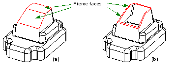
Generally, you need to open up a body when it is hollowed, so as to create, for instance, an open box from a solid block. You do this by specifying that one or more faces in the body should be pierce faces, that is, faces whose offset distance is zero. As part of the hollowing operation, each pierce face is reduced in size by performing a local boolean using any shared edges in their pre-offset and offset positions, so as to leave only the solid portion of the pierce face that remains after hollowing has taken place. This is illustrated in Figure 19-2.

Figure 19-2 Body with two pierce faces, before (a) and after (b) hollowing
You can specify which faces in a body should be treated as pierce faces using the available options, as described in Section 19.2.5, "Hollowing options".
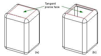
A tangent pierce face is a pierce face that shares at least one smooth edge with another face that is not a pierce face, as shown in Figure 19-3. If a pierce face has such a smooth edge, then it needs to be identified, so that side faces can be created along the smooth boundary edges.

Figure 19-3 Tangent pierce face before (a) and after (b) hollowing a body
You can specify whether or not to process tangent pierce faces using the available options, as described in Section 19.2.5, "Hollowing options".
You can manipulate individual offsets for faces in using fields in the options structure for PK_BODY_hollow_2:
| Field | Description |
|---|---|
|
An array of faces that should be offset by a distance other than the default. |
|
|
An array of offset distances corresponding to the array of faces in |
|
|
The level of checking that is to be applied to the modified body, which is either: |
|
|
Whether or not to process tangent pierce faces before offsetting begins:
Setting this option to PK_LOGICAL_true has no effect on the result if the body has no tangent pierce faces. If this option is PK_LOGICAL_true, then offset distances for all faces other than the pierce faces in the body must be the same. |
|
|
The offset method to use when hollowing. This is either: See Section 19.3.1, "Removing self-intersections" for more details. |
Offsetting is a fundamental part of the hollowing operation (as described in Section 19.2, "Hollowing"), and is also closely related to thickening (as described in Section 35.4, "Thickening a sheet body").
Offsetting can be performed as a separate operation by using PK_BODY_offset_2 and PK_FACE_offset_2. These functions are analogous to PK_BODY_hollow_2 and PK_FACE_hollow_3 and receive the same inputs.
When the faces to be offset are from a sheet body, it is possible that a tolerant body is produced from the original exact body, because some edge geometry at the boundary has to be approximated by SP-curves in order to generate the boundary curve. To solve this case, Parasolid approximates the bounding edges with SP-curves to a tolerance that is less than or equal to the tolerance supplied by your application.
Figure 19-4 illustrates a case of offsetting two faces whose underlying geometry is free-form. In this example Parasolid created new edge geometry where the offset surfaces intersected. For outward offsets (positive) this can mean extending the underlying surface(s) so that the offset surfaces meet, as shown.

Figure 19-4 Offset surfaces extended
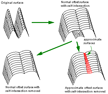
Creating accurate offset surfaces can sometimes introduce self-intersections which can cause problems with the associated offset, hollow, or thicken operation. Parasolid offers two ways of dealing with such self-intersections:
The first method guarantees that the resulting offset surface remains accurate, but may leave sharp edges. The second method produces a smoother offset surface, but parts of it are no longer accurately offset from the original surface.
These two methods are illustrated in Figure 19-5.

Figure 19-5 Generating approximate offset surfaces
You can control how self-intersections are removed using the
offset_method
field in the options structure for the function you are calling. This field can take two values:
The
offset_method
field is available in the following options structures:
In some cases, offsetting faces in a body requires the creation of additional side faces perpendicular to the faces being offset, as shown in Figure 19-6. This may be necessary either to improve the appearance of the final model, or to successfully offset the faces at all.

Figure 19-6 Creating step faces during offsetting
Such side faces are known as offset steps, and they can be created whenever the boundary edge (i.e. the edge between a face being offset and a face that is not offset) is smooth, as shown in Figure 19-7.

Figure 19-7 Cross section of body (a) before and (b) after offsetting using an offset step face
You can create offset steps using the
offset_step
option in the options structure for the function you are calling. This option takes the following values:
The
offset_step
field is available in the following options structures:
| <<< Local Ops: Transforming Faces | Chapters | Local Ops: Adding Draft >>> |