 |
Rendering Option Settings |
| <<< Rendering Functions | Chapters | Facet Mesh Generation >>> |
This section describes the options that you can set for PK_GEOM_render_line.
| Value | Description |
|---|---|
The description of the PK_TOPOL_render_line options contains further information about parametric hatching with an example of parametric surface output.
| Value | Description |
|---|---|
This section describes the options that you can set for PK_TOPOL_render_line.
| Value | Description |
|---|---|
By default, the edges of the model are always drawn.
The latter setting switches edge rendering off, allowing an application to generate view dependent and view independent graphics output data in separate calls to PK_TOPOL_render_line.
| Value | Description |
|---|---|
|
render silhouettes, but detect near-circular silhouettes and render them as arcs |
Silhouette lines are boundaries between locally visible and invisible faces. Each silhouette is assigned a unique label when it is constructed which as passed onto GO.
If a hidden line picture is required (implied by the visibility option setting), the silhouettes option must be set to a value other than PK_render_silhouette_no_c.
The PK_render_silhouette_arcs_c setting is a specialized option used in drafting which allows dimensioned arcs to be identified. This slows down rendering and is not recommended for general use.
Parasolid supports planar hatching, radial hatching and parametric hatching.
Planar hatching can be expensive to calculate for some types of surface, hence the other, surface-specific types of hatching.
When constructing hidden line drawings, hatch lines are classified as visible/invisible in a similar way as used when drawing the model edges.
Planar hatching instructs the function to output lines representing the intersections of a face with a family of equally spaced parallel planes.
The
planar_hatching
value defines the hatch spacing in model units.
The
axis
field of
planar_axis
specifies the normal direction of hatch planes.
The
location
field of
planar_axis
defines a point on one of the hatching planes which allows the application to control the relative position of hatch lines on a face. This option allows the application to simulate more complex hatch spacing by varying the location and calling PK_TOPOL_render_line multiple times.
The PK_render_planar_free_c option specifies that Parasolid should choose the start position for hatching.

Figure 53-1 Planar hatching (both cubes drawn with PK_TOPOL_render_line)
Radial hatching is used on cylindrical, spherical, conical, toroidal and blending faces (described below as radial faces).
The radial hatching parameters allow cross-hatching of faces to be specified, such as producing lines both along and around a cylinder.
| Value | Description |
|---|---|
|
apply radial hatching to radial faces which have a hatch attribute set using the defined attribute values |
|
|
apply radial hatching to all radial faces using some/all of the floating point values supplied in the options structure as detailed below (Parasolid chooses the starting values): |
|
|
apply radial hatching to all radial faces using some/all of the floating point values supplied in the options structure as above; to specify starting values for hatching, see options below (if none are supplied PK_render_radial_yes_c behaves like PK_render_radial_free_c with Parasolid choosing the starting values): |
The initialized values of zero imply that hatching is not required in a particular direction (the full meaning depending on the surface types).

Figure 53-2 Radial hatching using
radial_around
= pi/2 to control vertical hatch lines and
radial_along
= 7 to control the spacing between the circular hatch lines

Figure 53-3 Radial hatch (using the same option data as Figure 53-2)
The hatched torus looks messy using this value of
radial_along
to control the spacing between the circles centered on the spline.
If we use the
radial_about
value instead, to control this spacing by giving an angle to use between the planes which produce these intersection circles, it is much easier to control what happens.

Figure 53-4 Radial hatching using all three data options
The interpretation of different radial values for cylindrical and conical surfaces is as follows:
The interpretation of different radial values for spherical surfaces is as follows:
The interpretation of different radial values for toroidal surfaces is as follows:
| Value | Description |
|---|---|
radial_around |
controls the spacing of circular hatch lines centered on the axis of the torus, as would be generated by a cone (axis parallel to torus axis, passing through spine of torus) whose half angle is incremented by the given value, which must be in the range 0 to two pi |
radial_along |
controls the spacing of circular hatch lines centered on the spine of the torus, as would be generated by a plane rotating about the axis of the torus (see "radial_along specifies a distance along the spine; radial_about specifies an angle about the axis." below) |
radial_about |
controls the spacing of circular hatch lines centered on the spine of the torus, as would be generated by a plane rotating about the axis of the torus (see "radial_along specifies a distance along the spine; radial_about specifies an angle about the axis." below) |
radial_around_start |
|
radial_about_start |
|
radial_along_start |
The interpretation of different radial values for edge-blend surfaces is as follows:
| Value | Description |
|---|---|
radial_along |
controls the spacing of circular hatch lines running around the surface perpendicular to its spine, equivalent to the circles generated by this value for cylindrical surfaces (as would be generated by a plane stepping along the surface spine by the given distance) |
radial_around |
|
radial_about |
|
radial_along_start |
the parameter of the spine curve returned from PK_BLENDSF_ask |
radial_around_start |
|
radial_about_start |
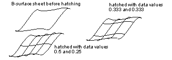
Parametric hatching instructs the function to output data corresponding to parametric hatch lines.
| Value | Description |
|---|---|
|
apply parametric hatching to any faces which have a hatch attribute set using the defined attribute values |
|
|
parametric hatching using |
|
|
parametric hatching using |
Parametric hatch lines can be output on any type of surface. The lines output are the locus of points of constant parameter on the equivalent B-surface.

Figure 53-5 Parametric hatching
On faces, the spacing starts at the low parameters of the parameter box of the faces, as returned by PK_FACE_find_uvbox.
This option is only available when drawing view independent topology.
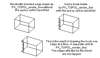
It instructs the rendering function to draw unfixed blends as they would appear when fixed.
If the entities being drawn are bodies or edges, an unfixed edge is not output directly. Instead the edges of the faces adjacent to the edge are clipped and rib lines are added at each end of and possibly along the spine of the unfixed blending edge.
If an unfixed blended edge is drawn in isolation, no other graphical information about the attached faces is output.
PK_EDGE_find_blend_topol can be used to find out which edges are affected by a blend. To get them to be clipped, these must also be passed as well as the blended edges.
The parameters of an unfixed blend are held as a blended attributes. These describe the start and end radii and possibly a specific rib spacing distance to use when the unfixed blend is drawn.
|
Warning: Unfixed blends cannot be specified in a view dependent or hidden line drawing. |

Figure 53-6 Unfixed blends, drawn with and without surrounding edges
A hidden line drawing classifies all lines (edges, silhouettes and hatch lines) into segments of differing visibility, depending on the view supplied.
The invisible portions of lines can be excluded from the drawing or be output marked as invisible. The latter option should only be used if your GO functions check for the visibility of lines before drawing, possibly outputting visible and invisible lines in a different style.
| Value | Description |
|---|---|
|
output hidden lines and distinguish between those hidden by other lines and those hidden by body |
|
|
visibility is evaluated - the information output is controlled by the |
The PK_render_vis_inv_draft_c setting is a specialized option which distinguishes between lines which are blocked by other lines and those which are obscured by other faces of the body, so that, for example, a plot of the image can be made in which no lines are drawn over the top of other lines.

Figure 53-7 Drafting style lines where no lines are drawn over the top of other lines
|
Warning: The PK_render_vis_inv_draft_c option cannot be used with a view transform entity whose underlying matrix has a perspective term. |
The PK_render_vis_extended_c option is described further in the "Invisible", "Drafting" and "Self hidden" sections.
The
smooth
option generates additional graphics output data which specifies whether an edge is "smooth", "not smooth" or "smooth but coincident with a silhouette" (for view dependent and hidden line drawings only).
The value for
smooth
indicates whether the direction of the normal to the surface varies continuously across the edge or not. Examples of smooth edges are blend boundaries and edges which have been scribed onto a face.
If the option is not given, all edges are output with their smoothness code set "unknown" (CODUNS).
Although an implementation of GO may choose to ignore smooth edges, (those output with smoothness code CODSMO), it must draw ones classified as coincident with a silhouette (marked with code CODSMS) or gaps will occur in the drawing, where the obscured silhouette line was found.
| Value | Description |
|---|---|
The PK_render_smooth_draft_c setting is a specialized option which detects cases where smooth edges are coincident with lines (other than silhouettes) and reclassifies these before output through GO as being obscured by the faces of the smooth edge (i.e. tagged as CODDRV) rather than being obscured by the smooth edge itself.
The reason for the option is to provide support for implementations of GO which simply ignore smooth edges; it avoids the case where a smooth edge obscures part of another edge and ignoring it would cause gaps in the drawing.
There is no need to use the smoothness option if your GO does not use smoothness data.
You can use the following two options to specify a tolerance within which an edge is considered smooth:
| Option | Description |
|---|---|
|
If PK_LOGICAL_true, If PK_LOGICAL_false, the angular tolerance used depends on the accuracy of the edge. |
|
|
The angular tolerance (in radians) for smooth edges. An edge is considered smooth if the angle between the normals of the two faces that meet at the edge is less than |

Figure 53-8 Angular tolerance for smooth edges
The
internal
option is used to specify whether to indicate internal edges, i.e. where faces on either side of the edge lie on the same surface.
| Value | Description |
|---|---|
By default, GO data is output with the internal edge value set to 'unknown smoothness'. If
internal
is used, the internal edge value is set to 'smooth', 'not smooth' or 'smooth but coincident with a silhouette'. The application can decide whether to suppress drawing the latter cases.
The regional data option can be used when rendering a hidden line drawing. It generates additional graphics output data which allow the application to analyze the projected (2-dimensional) hidden-line picture into distinct regions and link up the boundaries of the regions appropriately.
There is no need to use this option if your GO does not use such regional data.
| Value | Description |
|---|---|
|
output regional data for silhouettes and edges which bound faces which have the regional attribute set |
|
The additional data may be attached only to edge and silhouette segments, and is output as follows:
When the hidden-line picture is projected into two dimensions, the edges and silhouette lines become two-dimensional lines dividing the plane into distinct regions, as in the diagram:

Figure 53-9 Regional data - hidden line picture
For each of these regions that derives from a face with the SDL/TYSA_REGION attribute (if PK_render_region_yes_c is used, for all regions) the lines whose projections in the plane bound the region are all output with regional data. This data indicates which vertices in the image bound the line, and which faces are on each side of the line. Your application can then construct the loops and regions of the image.
The hierarchical output option can be used when rendering a hidden line drawing. It specifies that edges/silhouettes/hatch lines must be output through GO hierarchically, consisting of two calls to GOSGMT, enclosed by a pair calls to GOOPSG and GOCLSG.
The first call to GOSGMT defines the line segment type and its geometry.
The second call to GOSGMT defines a "visibility segment" (SGTPVP), specifying points at which the segment visibility or smoothness changes and the visibility codes for edges/silhouettes/hatch line between these points.
If geometry is being output in polyline form, there is an option which outputs an additional parameter with each visibility transition point corresponding to its position along the polyline.
| Value | Description |
|---|---|
|
do not output geometry segments, but do output visibility segment data |
|
|
output geometry segments and output visibility segment data with polyline parametrization |
The PK_render_hierarch_no_geom_c option can only be used if the segment geometry has been output in an earlier call to PK_TOPOL_render_line and has been stored by the application.
This option specifies which format is used by the graphics output functions to output rendering data for B-curves. This applies to B-curves which are defined in the model and to derived B-curves such as hatch and boundary lines on B-surfaces.
Curves are output in rational or non-rational form; depending on the order of the original curve or surface from which is was derived.
| Value | Description |
|---|---|
See Chapter 26, "The Mathematical Form of B-Geometry" for further information.
A viewport is a cuboid region of world space that is defined by a "non-aligned" box, with local x/y/z dimensions and a pair of orthogonal axes specifying its orientation.
You can use viewports when rendering a view dependent or hidden line drawing (i.e. in cases where a view transformation entity is given). If you specify one or more viewports, only the entities that are in those viewports are rendered.
You use the
viewport
option in PK_TOPOL_render_line_o_t to specify whether to use viewports. This takes the following values
When a single viewport is used (PK_render_viewport_yes_c) you provide it using the
viewport_sf
option in PK_TOPOL_render_line_o_t. This takes a standard form for a single non-aligned box.
When multiple viewports are used (PK_render_viewport_array_c),
viewport_sf
is ignored, and the viewports are specified using the following options in PK_TOPOL_render_line_o_t:
The
visibility
option PK_render_vis_extended_c enables the
invisible
,
drafting
, and
self_hidden
options: see sections 53.2.13, 53.2.14, and 53.2.15 respectively. These let you specify more precisely how the GO data should differentiate between different cases of obscured lines. These three options are ignored if
visibility
is not set to PK_render_vis_extended_c. See Section 53.2.5 for details.
This option specifies whether invisible lines are output when
visibility
is set to PK_render_vis_extended_c.
| Value | Description |
|---|---|
The resulting GO output is described in the "Visibility" section above.
This option determines whether or not a distinction is made between lines hidden by lines and lines hidden by faces when
visibility
is set to PK_render_vis_extended_c.
| Value | Description |
|---|---|
|
do not distinguish between lines hidden by other lines and lines hidden by faces (default) |
|
|
distinguish between lines hidden by other lines and lines hidden by faces |
The resulting GO output is described in the "Visibility" section above.
This option is used to determine whether or not a distinction is made between lines hidden by faces of their own occurrence and lines hidden by faces of another occurrence when
visibility
is set to PK_render_vis_extended_c.
| Value | Description |
|---|---|
|
do not distinguish between lines hidden by their own or another occurrence (default) |
|
|
distinguish between lines hidden by their own or another occurrence |
If the latter option is used, the GO data identifies lines which are made invisible as a consequence of being hidden by their own body occurrence.
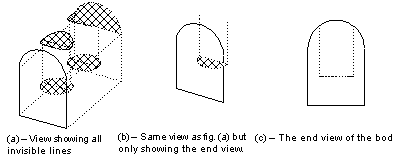
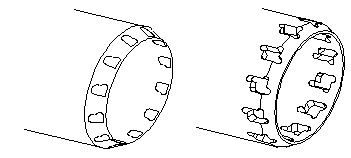
This option allows small features to be ignored, where a small feature is a set of connected faces whose box is smaller than a user-specified value. The small feature is replaced by a loop of edges which indicates the position of the boundary between the small feature and the model. These loops are either completely visible or invisible (see Figure 53-10).
|
Note: For this option to take effect, the visibility must
not be set to PK_render_vis_no_c. See Section 53.2.5. |
The options available for
ignore
are:
| Value | Description |
|---|---|
If
ignore
is set to PK_render_ignore_absolute_c then any feature whose size box is smaller than this value is ignored. If
ignore
is set to PK_render_ignore_ratio_c then the value input corresponds to the ratio of the feature box size to the size of the box containing the model, i.e. if this value is set to 0.01 then a feature is ignored if its box is smaller than 1% of the model's box.
Not all small features are ignored. This is determined by the position of the boundary between the small feature and the rest of the model, only if this boundary lies completely within a face of the model is the small feature ignored.
In the left-hand illustration of Figure 53-10 the boundaries of the small features lie completely within another face in the model. These features are replaced by a loop of edges indicating where the features lie on the model. Each edge in these loops is still output, but is labeled with the code 'CODIGN' where it would normally have its 'internal' property output. See Section B.2, "GOSGMT - output non hierarchical segment", in the Downward Interfaces manual for information about CODIGN.
In the right-hand illustration of Figure 53-10 the boundaries of the small features lie across the boundary of two faces. These features cannot be ignored.

Figure 53-10 Ignoring small features - demonstrating small features that can be ignored and those that cannot.
This option allows assemblies and lists of bodies that overlap in model space to be hidden line rendered such that the results are predictable and stable. Where the edges and silhouettes of one body intersect with the face of another, those lines are trimmed to the intersecting face. New intersection curves are not generated at the intersection.
|
Note: For this option to take effect, the visibility must
not be set to PK_render_vis_no_c. See Section 53.2.5. |
The values available for
overlap
are:
| Value | Description |
|---|---|
If
overlap
is set to PK_render_overlap_no_c, Parasolid assumes that the bodies being rendered do not overlap. If there are overlapping bodies present then the overlap is not detected and the resulting picture may contain errors.
If
overlap
is set to PK_render_overlap_yes_c, Parasolid detects the presence of overlapping bodies and splits the existing lines appropriately. However, new edges are not generated where the faces of the overlapping bodies intersect.
Figure 53-11 demonstrates the effect of each of these settings on a rendered image. It shows a cylinder passing through a cylindrical hole drilled in a block; the diameter of the cylinder being slightly larger than the diameter of the hole so that the cylinder and the block overlap.

Figure 53-11 Overlapping bodies - demonstrating the effect that the overlap option has on a rendered image
In the left-hand illustration of Figure 53-11,
overlap
is set to PK_render_overlap_no_c. Parasolid does not detect that the silhouettes of the cylinder intersect the block and they are not output with the correct visibility.
In the right-hand illustration of Figure 53-11,
overlap
is set to PK_render_overlap_yes_c. The silhouettes of the cylinder are intersected with the face and are rendered correctly.
You can let your application have a degree of control over the amount of system resources during hidden line operations using the
memory_target
and
memory_target_value
options for PK_TOPOL_render_line. These options let you specify a peak memory value that Parasolid attempts to keep within during the call to PK_TOPOL_render_line.
Controlling memory usage during hidden line operations can be useful for:
Although this technique results in an increase in total processor time, in certain cases it can result in a decrease in the elapsed (real) time taken to render the assembly.
Parasolid does not guarantee to meet the specified target.
| Option | Description |
|---|---|
|
Whether to keep memory usage within a specified value. This can be one of:
|
|
|
A target value, in bytes, that Parasolid attempts to keep memory usage within during the call to PK_TOPOL_render_line. |
|
Note: For this option to take effect, the visibility must
not be set to PK_render_vis_no_c. See Section 53.2.5. |
Using this option can bring varying degrees of success, depending on the target you specify, the resources available on the machine, and the size of the assembly that you are rendering. Different memory targets and different assemblies may yield improvements in memory usage, or elapsed time taken to render, or both.
Your application could typically follow these steps in order to calculate a suitable target memory value:
For large assemblies, a memory target in the region of 100MB may be possible, regardless of the original memory requirement. Using this option may let you render some assemblies successfully that would otherwise be unrenderable.
| <<< Rendering Functions | Chapters | Facet Mesh Generation >>> |