 |
Facet Mesh Generation |
Facet Mesh Generation
| <<< Rendering Option Settings | Chapters | Faceting Output Via GO >>> |
Values used by the PK_TOPOL_facet_mesh_o_m macro to initialize the PK_TOPOL_facet_mesh_o_t structure are described here as default settings. These settings demonstrate how to have basic topological and geometric data returned to the application.
Applications should initialize the PK_TOPOL_facet_mesh_o_t structure using the macro, rather than trying to set all of the fields individually. The value of the
o_t_version
field which is initialized by the PK_TOPOL_facet_mesh_o_m macro must not be modified.
Some of the facet mesh options require a viewing matrix to be specified. Parasolid has a number of requirements on such matrices, as explained in the sections on the "Density" and "Cull" options below.
View matrices are explained in Chapter 49, "Parasolid View Matrices".
A number of the facet mesh options can take a tolerance value. It is assumed that if no explicit tolerance value is provided, Parasolid is free to calculate its own internal tolerance values. These are generally case specific, rather than using specific fixed values.
The following sections describe the fields in the PK_TOPOL_facet_mesh_o_t option structure.
The
shape
field constrains what shape of facets are allowed in the facet mesh. The options are:
| Option | Description |
|---|---|
|
PK_facet_shape_convex_c (default) |
facets are generated so that all interior angles are convex and none of the facets contain interior holes |
|
the application permits concave interior facet angles, and none of the facets contain interior holes |
|
|
the application permits concave interior facet angles, and the application permits facets to contain interior holes |
The convexity test is made by projecting the facet fins onto the mid-plane of the facet and testing its interior angles. The "mid-plane" is defined under "Facet planarity tolerance".
The PK_facet_shape_cut_c and PK_facet_shape_any_c settings are only relevant where facets can contain more than three sides as specified by the "Maximum number of sides on facets" option.
If PK_TOPOL_facet is being used to return tabular facet data with the
shape
field set to PK_facet_shape_any_c, any facets containing holes are defined in the
facet_fin
table using the
null_index
marker to separate the exterior fin boundary from the interior fin boundaries. This format is described in the "Facet topology" section of Chapter 56, "Tabular Output of Faceting".
When solid or sheet parts are faceted, the
match
option allows faces to be faceted independently or faceted together as a complete mesh. The options are:
| Match type | Option | Description |
|---|---|---|

Figure 54-1 Geometry matching - clipping facet boundaries to a common edge
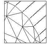
Figure 54-2 Topology matching - matching facet vertices across a common edge
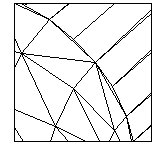
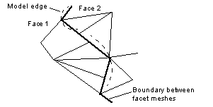
Figure 54-3 Trimmed matching - clipping facet boundaries to model edge curves
The geometry matching option (PK_facet_match_geom_c) can be used when generating faceted output for a simple rendering application.
The boundaries of neighboring facet meshes (generally) meet exactly but are topologically disjoint. If PK_TOPOL_facet is being used to return tabular facet data, the
fin_fin
table only matches fins which belong to the same face (the co-fin values of fins on the face mesh boundary are set to a null index value).
Facet meshes may not match in the following situations:
|
Note: When general bodies are faceted, this must be done using the geometry matching option, so that faces are faceted independently of each other. |
The topology matching option facets all of the faces of a solid or sheet part as a single mesh.
If PK_TOPOL_facet is being used to return tabular facet data, the
fin_fin
table describes matching between fins which belong to the same face and between boundary fins which belong to the neighboring faces.
The topology matching option checks that the boundary vertices on a facet mesh always match with vertices on the boundaries of neighboring meshes (possibly splitting facets in the neighboring facet mesh in order to meet this condition).
The topology matching option corrects the problem of slight gaps described in the "Geometry matching" section.
The trimmed facets option clip facet boundaries to model edge curves.
It gives no matching between facets on the two faces of an edge, but ensures that the gaps or overlaps between such facets are no bigger than the supplied tolerances. Figure 54-3 shows the gaps occurring along a model edge.
The
density
field allows the facet density to be increased over regions of the part which become silhouettes when viewed with a parallel view in the direction specified by the view matrix.
| Option | Description |
|---|---|
|
PK_facet_density_no_view_c (default) |
|
This option is used when generating view specific facet meshes which contain enhanced detail where the facet surfaces form silhouettes against the specified view. This option requires a view and local tolerance values to be specified.
The view is defined by the
view_transf
parameter given in the call to PK_TOPOL_render_facet or PK_TOPOL_facet:
You can also define multiple views, using the
view_directions
option. If you use
view_directions
, it overrides
view_transf
for local density values. See Section 54.2.4, "Multiple view directions", for details.
There is further information on view matrices in Chapter 49, "Parasolid View Matrices".
See Section 54.2.5, "Local density", for descriptions of the
local_density_tol
and
local_density_ang
fields.
You can increase the facet density in multiple view directions using the
view_directions
option. This takes as its value an array of unit vectors, each unit vector defining a different view direction. A corresponding
n_view_directions
option contains the number of view directions, and should correspond with the size of the
view_directions
array.
This option overrides any view direction specified using
view_transf
(as described in Section 54.2.3). By default,
n_view_directions
is set to 0 to ensure that
view_transf
is not overriden unless explicitly requested.
Note: When culling back facing facets, the direction defined by
view_transf
is used, rather than any directions defined by
view_directions
. See Section 54.2.6, "Cull" for more information about culling facets. |
The local density tolerance values are required when
density
is set to PK_facet_density_view_c option (to specify that facet density is increased in regions where a silhouette is formed with a given view).
The default setting of
is_local_density_tol
and
is_local_density_ang
is PK_LOGICAL_false.
One or both of these fields must be set to PK_LOGICAL_true and one or both of
local_density_tol
and
local_density_tol
, must be set to a non-zero, positive value when using the PK_facet_density_view_c option.
The
cull
field allows the total size of the facet mesh to be reduced by removing some backward facing facets from the net.
| Option | Description |
|---|---|
|
PK_facet_cull_none_c (default) |
|
The view is defined by the
view_transf
parameter given in the call to PK_TOPOL_render_facet or PK_TOPOL_facet (see Section 54.2.3):
There is further information on view matrices in Chapter 49, "Parasolid View Matrices".
When this option is chosen it is not possible to have topology matching on. Therefore, since topology matching is the default, you must select a matching option other than PK_facet_match_topol_c. See Section 54.2.2, "Match" for more details.
The
n_loops
and
loops
options allow specific PK_LOOP_t entities to be ignored when a sheet body or a face of a sheet body is faceted. This has the effect that specified holes can be capped when sheet entities are faceted.
Each entity is a loop which is owned by one of the sheet bodies (or faces of a sheet body) which are being faceted.
The default setting is not to ignore any loops.
The
max_facet_sides
field constrains the maximum number of sides on facets. The default value is 3.
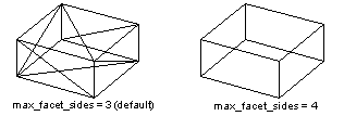
Figure 54-6 Maximum number of sides on facets
The
is_min_facet_width
and
min_facet_width
options constrain the minimum width of any side of a facet.
| is_min_facet_width | min_facet_width | Description |
|---|---|---|
|
Parasolid calculates an appropriate value based on the size of the face box |
||
|
set to the required minimum facet width (a positive, non-zero value) |
The value specifies a width below which Parasolid may disregard supplied curve, surface and planarity tolerance values. Facets may be produced with dimensions smaller than this width.
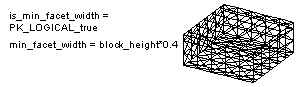
Figure 54-7 Minimum width of any side of a facet
The
is_max_facet_width
and
max_facet_width
options constrain the maximum width of any side of a facet.
| is_max_facet_width | max_facet_width | Description |
|---|---|---|
|
set to the required maximum facet width (a positive, non-zero value) |
The following sets of fields control how closely the fins on the boundaries of a face mesh match the originating edge geometry.
The default setting of each of
is_curve_chord_tol
,
is_curve_chord_max
and
is_curve_chord_ang
is PK_LOGICAL_false. This implies that no explicit curve tolerance values are supplied (Parasolid calculates appropriate tolerance values internally).
One or more of these fields can be set to the value PK_LOGICAL_true with one or more of the corresponding fields -
curve_chord_tol
,
curve_chord_max
,
curve_chord_ang
- set to a non zero, positive value.
The following sets of fields control how closely each face mesh matches the surface geometry of the originating face.
The default setting of
is_surface_plane_tol
and
is_surface_plane_ang
is PK_LOGICAL_false. These imply that no explicit surface tolerance values are supplied. (Parasolid calculates appropriate tolerance values internally).
One or more of these fields can be set to the value PK_LOGICAL_true with one or both of the corresponding fields,
surface_plane_tol
or
surface_plane_ang
set to a non zero, positive value.
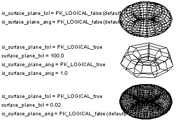
Figure 54-8 Examples of different surface tolerance settings
You can attach local tolerance to individual or groups of topological entities (either faces or bodies) which then override the faceting tolerances already defined for the face or body using the various curve and surface tolerance options available (see Section 54.2.11 and Section 54.2.12 respectively).
Local tolerances are specified using the following options:
| Option | Description |
|---|---|
|
A set of tolerances to be attached to entities. This is an array of PK_facet_local_tolerances_t. Default: 0 (empty). |
|
|
An array of unique topological entities (faces or bodies) to which you want to attach local tolerances. |
|
|
A list of indexes into the |
There are a number of ways that you can manage facet output at degenerate vertices. Parasolid lets you control:
You use the
degen
(PK_facet_degen_t) option in PK_TOPOL_facet_mesh_o_t to specify which one you want to use. The values it can take are as follows:
| Value | Description |
|---|---|
|
Each facet adjacent to a degeneracy has a unique vertex at the degeneracy. The value for the degenerate parameter at each vertex is the value of the degenerate parameter found for the previous vertex in the facet. Normals and derivatives for each facet are calculated using the appropriate parameter, and so are guaranteed to be accurate for each facet. However, the topology of the original part is not preserved. This is the default setting. |
|
|
Parasolid creates a single vertex which is used by all the facets adjacent to the vertex. The value for the degenerate parameter at this vertex is taken from the lowest value at the other end of one of the facets. This preserves the topology of the original, but the parameters, normals and derivatives of all other facets are incorrect. This option only has an effect if using tabular faceting via PK_TOPOL_facet. See Chapter 56, "Tabular Output of Faceting" for more information. |
|
|
Like the default method, each facet adjacent to a degeneracy has a unique vertex at the degeneracy, with a unique parameter. The normals and derivatives are therefore correct for each facet adjacent to the degeneracy, but topology is not preserved. Unlike the default setting, the value for the degenerate parameter at each vertex is taken from the average value of the degenerate parameters found for the vertices on either side. |
The differences between these three options are illustrated in Figure 54-9.
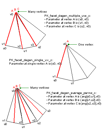
Figure 54-9 Creating facet vertices at degeneracies
This is managed first by the initial division of a face into a small number of facets. Each facet is then tested to see if it meets the tolerance criteria, i.e. surface tolerance, maximum size, etc. If the facet does not meet the criteria it is then split into two and each resulting facet is again tested as before. This process continues until the criteria are satisfied. However, if the process comes to a point where a facet has been produced which is smaller than the minimum width, then the recursion stops, regardless of the other criteria.
The following sets of fields control how closely the coordinates of a facet are matched to a common mid_plane. This is defined as passing through the center of gravity of the facet vertices, in a direction given by averaged value of the vertex normals.
| Switch field | Value field | Description |
|---|---|---|
|
an upper bound on the distance from a facet to its mid-plane |
||
|
the maximum permitted ratio between |
The facet planarity tolerance values are are only relevant where facets can contain more than three sides.
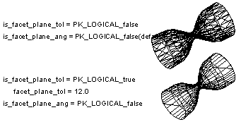
Figure 54-10 Examples of different planarity tolerance settings
You can control how facets are created for faces that contain wire edges using the
wire_edges
option. This takes the following values:
| Value | Description |
|---|---|
|
PK_facet_wire_edges_no_c (default) |
Faceting ignores wire edges in faces, and they are faceted over |
|
Faceting takes wire edges in faces into account and facets the face in such a way that no facet is intersected by a wire edge. |
The behavior of this option is illustrated in Figure 54-11.
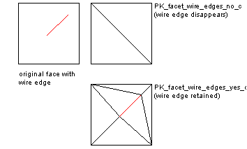
Figure 54-11 Faceting faces that contain wire edges
Small features in a body or model may be ignored during faceting operations. A small feature is a set of connected faces whose box size is smaller than a user-specified value. Doing this can speed up faceting, and reduce the number of facets created. It is useful if you are generating a "draft view" of a model, in order to get a rough idea of what it looks like. You use the
ignore
,
ignore_value
, and
ignore_scope
options in PK_TOPOL_facet_mesh_o_t to control whether, and how, small features are ignored.
| Option | Description |
|---|---|
|
Control whether to ignore small features. This can take the following values:
For a description of the difference between these last two values, see "Defining small features using a ratio value". |
|
|
Define which features are classed as small. This option takes either:
The default is 0.0. See "Defining small features using a ratio value" for more information. |
|
|
This option lets you specify the scope within which loops in a face may be ignored. It only applies when faceting a list of faces. The option can take two values:
The value of |
Note: If the
loops
option is used, faceting ignores the specified loops regardless of the value of
ignore
. See Section 54.2.7, "Loops", for information. |
The PK_facet_ignore_ratio_c and PK_facet_ignore_body_ratio_c values for
ignore
let you define the size of a small feature in terms of a ratio, rather than an absolute value. This is useful, because you can ignore small features without having to know anything about the overall size of the model. For example, specifying an
ignore_value
of 0.01 when using one of the ratio values means that any feature whose box size is less than 1% of the size of the entire model or owning body is ignored, regardless of its absolute size.
Two ratio values are available so that you can choose whether to define small features in terms of either the owning body or the entire assembly.
Value for
ignore
|
Ratio defined relative to |
|---|---|
If faceting bodies, the overall box is the union of all the
topols
boxes (with
topol_transfs
applied) in the call to PK_TOPOL_facet or PK_TOPOL_render_facet.
If faceting a list of faces, the overall box depends on the value of
local_scope
:
Value for
local_scope
|
Definition of overall box |
|---|---|
|
The union of all the |
|
|
The union of all the |
| <<< Rendering Option Settings | Chapters | Faceting Output Via GO >>> |