 |
Tabular Output of Faceting |
| <<< Faceting Output Via GO | Chapters | Bulletin Board >>> |
This chapter describes the method
used by PK_TOPOL_facet to return facet data to the application. Facet information is returned in tabular format, defining the facet mesh in terms of connected facet, fin and vertex indices.For information on the graphical output of facet geometry, see Chapter 55, "Faceting Output Via GO".
The options structure PK_TOPOL_facet_choice_o_t controls which types of faceting data are returned in tabular form. These are divided into three categories:
The support macro PK_TOPOL_facet_choice_o_m sets a minimal selection of these fields to the value PK_LOGICAL_true, sufficient to demonstrate how to output sample data for a simple rendering application.
The PK_TOPOL_facet_choice_o_t structure should always be initialized this way, rather than trying to set all of the fields individually. The value of the
o_t_version
field which is initialized by the PK_TOPOL_facet_choice_o_m macro must not be modified.
After the initialization stage, the application can set other fields in the PK_TOPOL_facet_choice_o_t structure to PK_LOGICAL_true which calculates and returns additional data.
The following code shows how each part of the PK_TOPOL_facet_o_t options structure must be initialized, prior to calling PK_TOPOL_facet.
/* declaration and initialization */ PK_TOPOL_facet_o_t my_option_struct; PK_TOPOL_facet_mesh_o_m (my_option_struct.control); /* set default mesh options */ PK_TOPOL_facet_choice_o_m (my_option_struct.choice); /* set default table choices */ /* now set application specific mesh options */ my_option_struct.control.<field1> = <value1>; my_option_struct.control.<field2> = <value2>; /* and set application specific choice of tables to output */ my_option_struct.choice.<field1> = <value1>; my_option_struct.choice.<field2> = <value2>; /* ... now call PK_TOPOL_facet(...); */ |
The tabular data is returned in the PK_TOPOL_facet_choice_r_t structure. It defines totals for:
and pointers to arrays of data which define facet topology, geometry and associated data.
Each facet is identified by an integer index. It is defined as an ordered sequence of fin indices which join numbered vertices.
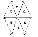
Figure 56-1 shows a hexagonal face mesh consisting of six facets f0 to f5 referring to seven facet indices v0 to v6. Fin numbering is not shown.

Figure 56-1 Hexagonal face mesh
Facet vertex v1 is described as an interior vertex (the remainder which lie on the mesh boundary are described as exterior vertices).
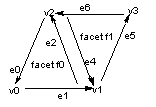
Figure 56-2 shows facet f0 and one of its neighbors f1 in schematic form:

Figure 56-2 Facets in schematic form
Parasolid uses a convention that facet fins follow an anticlockwise ordering when the facet mesh is viewed from the outside of a face.
Using this sequence, each fin is associated with exactly one vertex, lying at its head (shown on the diagram as the vertex closest to the arrow heads of each fin).
The topology of the facet mesh is described by the connectivity between a facet and its fin and vertex indices. The facets f0 and f1 are defined as:
The relation between two types of topological entity (facet/fin/vertex) is described as a table. Each table has an abbreviated name, formed from the names of the component entities.
In the examples shown above, the relation from a facet to its fins is described as the
facet_fin
table and the relation from a fin to its head vertex as the
fin_vertex
table.
These abbreviated table names are used as field names in the PK_TOPOL_facet_choice_o_t structure (to select the tables) and the PK_TOPOL_facet_r_t structure (to return the tabular definitions).
The
facet_fin
relation is represented by a two column table which groups sets of fins owned by the same facet together. The example shows that facet i is formed by 3 fins, in connectivity order e0, e1, e2.
| facet | fin |
|---|---|
|
Note: The groups of facets (in the first column) are in numerical order. The section "processing the returned data" describes how this ordering can be used to reduce search times. |
If a facet contains holes (having been created with the
shape
option set to PK_facet_shape_any_c), it is represented by an ordered sequence of exterior fins, followed by one or more sequences of interior fins, representing holes in the facet. The exterior and interior subsequences of fins are separated from each other by null fin markers with a value of -1.
The fin sequence of each interior hole in a face follows a clockwise order when viewed outside the facet. The relative ordering of each interior fin subsequence is arbitrary (other than following the exterior sequence).

Figure 56-3 Fin sequence of interior holes
In Figure 56-3, the relative ordering of the three interior subsequences "e5 e6 e7", "e8 e 9 e10" and "e11 e12 e13" is arbitrary.
Facets do not contain holes (and fin sequences do not contain null fin separators) if the
shape
option was set to PK_facet_shape_cut_c or PK_facet_shape_convex_c.
The
fin_vertex
relation is represented by a one-column table which maps fin indices onto vertex indices. The example shows that the head of fin a refers to vertex index p.
| fin | vertex |
|---|---|
The hexagonal face mesh in Figure 56-1 shows that facets f0 and f1 are adjacent. The schematic diagram (Figure 56-2, with definitions of f0, f1 and their constituent fins) shows that these faces are connected where fin e2 (of facet f0) meets fin e4 (of facet 1).
This is called a fin to co-fin matching.
Fins which lie within a facet mesh boundary are termed "interior" fins. These are always associated with a co-fin, connecting the same vertices as the first fin but in the opposite direction.
Fins which lie on a facet mesh boundary are termed "exterior" fins.
By default (using the PK_facet_match_topol_c match option set by PK_TOPOL_facet_mesh_o_m) coincident exterior fins from adjacent face meshes are matched to each other. Interior fins within the same face are always matched to each other.
This connectivity data is returned in the
fin_fin
table.
If faces are faceted in isolation, if the geometry matching option is used or if a sheet body is faceted which has a laminar edge, external fins are not matched against the fins of other faces and the co-fin is set to a null fin value (-1).
The value -2 may occur in the fin_fin table for one of two reasons:
The
fin_fin
relation is represented by a one-column table which maps fin indices into their co_fin indices.
The following example shows that fin a has co_fin d and fin b has no co_fin. The fin (and co_fin) indices listed here are all in the range from 0 to
number_of_fins
-1.
| fin | co_fin |
|---|---|
The next example shows where four fins (p, q, r, s) are coincident.
The fin table identifies this special case by using the same value V for all four entries. this is called a virtual fin index. The value V is greater than one or equal to
number_of_fins
.
| fin | co_fin |
|---|---|
Such cases can only arise when faceting general bodies and where more than two faces meet at a common edge.
If the application facet data structure can represent non-manifold topology
fin_vertex
and
vertex_normal
tables can be used to classify the common fins into parallel or anti-parallel categories and to order them around a line joining their common pair of start vertices.
If the application facet data structure is unable to represent such cases (where more than two facets meet at a common edge), the simplest default action is to consider the fins as unmatched.
The following code fragment demonstrates a test for a fin having exactly one co-fin.
int co_fin_num = table->fin_fin.fin[fin_num];
if (co_fin_num != -1 && co_fin_num < table->number_of_fins)
{
...
Applications should be written to detect virtual fin values even if they do not currently use Parasolid general bodies.
This avoids array bounds errors occurring at a later date.
Facet topology is mapped onto geometry using the intermediate tables:
These are all one-column tables with a length of
number_of_vertices
. They contain integer indices which refer to entries in the
point_vec
,
normal_vec
or
param_uv
/
param_dp
/
param_d2p
tables.
If a cube is faceted using 3 sided facets, the tabular structure refers to:
Each face mesh contains 2 facets, defined by a total of 6 fins and 4 vertices.
The following diagram shows the connectivity in schematic form:

Figure 56-4 Facet fin and vertex connectivity
The geometry tables are accessed by index values which are defined in the
vertex_point
,
vertex_normal
and
vertex_param
tables.
Obtaining a facet vertex's coordinates is a two stage progress:
point_index
is obtained from the
vertex_point
table using the vertex index value.
point_vec
table using the point index value.Obtaining a vertex's surface normal is a two stage process:
normal_index
is obtained from the
vertex_normal
table using the vertex index value.
normal_vec
table using the normal index value.Surface normal values are returned as normalized vectors, pointing away from the originating face.
If the surface normal cannot be calculated, a zero vector is returned. This event is rare but applications should test for it.
Obtaining a vertex's surface parametrization and/or derivative data is a two stage process:
param_index
is obtained from the
vertex_param
table using the vertex index value.
param_index
value.These three tables are all accessed using the same param_index value. If surface derivative vectors cannot be calculated, a zero vector is returned.
These tables define the association between facet entities and their originating model entities.
The
facet_face
relation is represented by a one-column table which maps facet indices back to their originating face entity values. Sets of facets derived from the same face are grouped together.
| facet | face |
|---|---|
The example shows that facets i and j were both derived from face f.
This relation is intended to provide an additional column of data for the facet_face table. This defines which occurrence of a topological entity in the PK_TOPOL_facet parts array is the owner of a facet index value. This is provided for future expansion; it is returned empty.
The edge_fin relation is represented by a two column table which associates sets of fins derived from the same edge. The table of edges and fins is returned unsorted, which means that a set of fins associated with a specific edge may not appear in contiguous positions in the table. The fin entries associated with a specific edge are not sorted by the owner face or by the relative position of the head vertex along the edge. Interior fins do not appear in this table.
The example shows that the fins e0, e1, e2, e3 were all derived from the same PK_EDGE_t entity E1. The fin sequence is not ordered. It shows that the fin entries for a specific edge are dispersed through the table. Entries can be classified into fin and co-fin categories and sorted into connectivity order using the facet topology tables.
| edge | fin |
|---|---|
This relation is intended to provide an additional column of data for the edge fin table. This defines which occurrence of a topological entity in the PK_TOPOL_facet parts array is the owner of a fin index value. This is provided for future expansion; it is returned empty.
This relation indicates whether any faults were detected during faceting. The table is returned as an array of paired integers:
The following categories of faceting faults are detected.
The specified PK_BODY_t entity could not be faceted due to an invalidity in the body. No facet mesh is generated for this body. For example, if the body is not entirely contained within the Parasolid size box, this could result in numerical errors which prevent the body from being faceted, in which case the body is returned along with the token PK_facet_fault_body_c.
The specified face could not be faceted using the given mesh generation options - the output facet mesh is not complete.
Where possible, your application should inform the user that an error has occurred rather than simply ignoring missing faces. This is particularly important when passing generated facet data onto further analysis programs.
A possible reason for this fault s that faces on the part being faceted are corrupt. This can be checked by calling PK_BODY_check with the geometry options enabled.
The specified facet is disconnected from some of its neighboring facets. The topology of the generated facet mesh is valid but it may define one or more slit edges around the specified facet. This warning is only relevant in cases where an application walks the returned facet mesh (it is ignored by rendering applications).
The coordinates of the specified vertex have been modified in order to match the coordinates on an adjacent face. This usually fixes inconsistencies in facet vertex geometry along a common faceted edge. This is provided for Parasolid diagnostic purposes; it can be ignored by applications.
Parasolid was unable to calculate an accurate surface normal at the specified facet vertex position. The entry referenced by the corresponding
vertex_normal
table is not a valid normal vector. A possible reason for this fault is that the part being faceted is corrupt.
Parasolid was unable to calculate first and/or second order derivative data at this facet vertex position. Some surface derivative values referenced by the corresponding
vertex_param
table are not valid.
No facets were output for the specified face because the face is very thin.
|
Note: Although a facet may not be output for a given thin face, this is not an indication that faceting has failed. |
Tabular data returned by the PK faceting functions are unlikely to be suitable for direct use by an application.
This section suggests some techniques which can reduce the time taken to convert the tabular output data into an application data structure.
The
fin_vertex
table can find the head vertex of a fin directly. The tail vertex cannot be found directly, it is either found by looking at the head vertex of the co_fin or by looping around all of the fins in the facet.
If the application data structure wishes to attach head and tail vertex pointers to its fin definitions, it is more efficient for it to construct an additional
fin_prev_vertex
table and to initialize this in a single pass (by offsetting the returned
fin_vertex
data).
The additional table allows a fin's tail vertex to be accessed directly.
If an application data structure wishes to store a list of facets which are attached to a point, this can be constructed by finding which vertices are attached to a point, then locating their owning facet.
Neither operation can be performed efficiently using the returned tabular data directly.
If an inverted
point_vertex
table is constructed from the returned
vertex_point
table, this lookup can be performed efficiently. The implementation must allow for many facet vertices being associated with a single point.
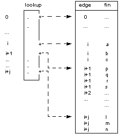
If an application wishes to find which fins belong to an edge, time can be wasted locating which row of the edge column contains the required fin index.
The search time can be reduced by sorting the edge_fin table into by edge value, then constructing a supplementary lookup table which maps edge values onto the start index of the first matching fin. (The method requires the lookup table to contain the PK_EDGE_t entity values in addition to the start index pointers which are shown below).

The virtual memory which is referenced by the PK_TOPOL_facet_r_t must be freed by the application, once it has been copied into the application's faceted data structure. The code fragment demonstrates how this can be done:
if ( table != NULL ) { if ( table->facet_fin.length > 0 ) PK_MEMORY_free( table->facet_fin.data ); if ( table->fin_fin.length > 0 ) PK_MEMORY_free( table->fin_fin.fin ); ... |
| <<< Faceting Output Via GO | Chapters | Bulletin Board >>> |