 |
Boolean Operations |
| <<< Checking | Chapters | Instancing and Patterning >>> |
It is assumed that you are familiar with the characteristics of the various body types, as explained in Chapter 6, "Manifold Bodies"and Chapter 7, "General Bodies".
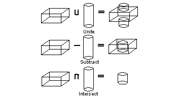
The basic boolean operations are analogous to mathematical set operations:

Figure 9-1 Basic boolean operations
This section explains the most relevant terminology that is associated with this chapter.
The "operands" of a boolean are called the target and the tool. The target of a boolean is the body you begin with, and the tool is the body you operate on it with. The target is modified by the tool, and the tool is deleted at the end of the operation. Parasolid preserves the tags of entities in the target as far as possible.
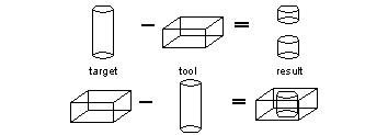
The following diagram shows the effect of swapping the target and tool of subtract:

Figure 9-2 Target, tool and result bodies on boolean subtraction
This is important when we come to consider Booleans between bodies of different types.
The rules for the persistence of tags described in Section 2.2.2, "Tags", apply during boolean operations. However, tag persistence is disabled if normal attribute callbacks are registered and used. See Section 46.3, "Callback functions" for more information.
A global boolean is characterized by the comparison of all face pairs from the target and tool bodies.
These boolean operations are supported by the PK_BODY_boolean_2 function which requires one target body, one or more tool bodies and an options structure. If more than one tool body is supplied, the union of overlapping tools is computed first and then the boolean between the target and the tools is performed.
The following functions support boolean operations without requiring the specification of an option structure:
A local boolean is characterized by the comparison of selected face pairs in the target and tool bodies. This form of boolean operation is quicker than a global boolean but does not guarantee topological consistency on the resulting bodies.
These boolean operations are supported by the PK_FACE_boolean_2 function which requires one or more faces from a single target and tool body and an options structure.
The imprinted edges divide the boundaries of the bodies into regions.

Figure 9-3 Using this target/tool combination in a boolean operation...

Figure 9-4 ... creates these boundary regions (imprinted edges and regions on tool are marked)

Figure 9-5 ... or creates these boundary regions after imprinting between f1 and f2 (imprinted edges and regions on tool are marked)
The result of a boolean operation with generalized topology disabled, may be any number of bodies, each of which is a manifold and connected solid or sheet. Global and local boolean operations may be attempted with manifold topology.
The manifold boolean operations behave as follows:
The behavior of the subtraction operation can be altered for:
The result of a boolean operation with generalized topology enabled is a single general body which may be disconnected, non-manifold, of mixed dimensions (or any combination of these). Only global boolean operations may be attempted with generalized topology.
The generalized topology boolean operations behave as follows:
Irregular Boolean operations (such as boolean operations between two open shells) are supported when generalized topology is enabled.
To enable generalized topology, use PK_SESSION_set_general_topology.
The behavior of the boolean interface functions, PK_BODY_boolean_2 (global Booleans) and PK_FACE_boolean_2 (local Booleans), is altered via the contents of an option structure passed to these functions. The option structures for these functions are different, but overlap with respect to a number of options. The options are as follows:
| Option | Description |
|---|---|
|
specifies the boolean operation to be performed: union, subtraction or intersection |
|
|
specifies that all mergeable imprinted edges created by the boolean operation are merged |
|
|
modifies the edge merging behavior - the merge phase avoids merging edges in the imprint that existed and were mergeable before the start of the boolean |
|
|
specifies that the boolean operation should return a single disjoint body if the operation would result in more than one body |
|
|
specifies that all solid regions in the resulting body are pruned - any faces, edges or vertices in the result body which are completely surrounded by solid regions are deleted |
|
|
specifies that all void regions in the resulting body are pruned - any faces, edges or vertices in the result body which are completely surrounded by void regions are deleted, so long as the result body contains some pieces of a higher dimension, e.g. a sheet face is only deleted if the result body contains at least one solid region |
|
|
modifies the behavior of the subtract operation and determines which resultant bodies are returned when performing solid/ sheet (trimming) or sheet/solid (punching) boolean operations |
|
|
a local boolean receives a subset of the faces of a target body - if the imprinting phase of the boolean results in incomplete loops of imprinted edges, then additional target faces are used |
|
|
stop self intersection, after imprinting, tool faces which survive the boolean are compared against all faces of the target body |
|
|
this option sub-structure describes the configuration of the tar get and tool bodies - see "Optimizing boolean operations (global & local)" for a description of the options |
|
|
this option sub-structure is used to identify regions of the tool to be included or excluded in the boolean result - see "Select regions in boolean operations (local)" for a description of the options. |
|
|
this option sub-structure describes matched regions between the target and tool bodies - see Section 9.6.3, "Matched topology in boolean operations (global & local)" for a description of the options |
|
|
checks faces involved in the boolean operation - only faces which are adjacent to imprinted edges are checked |
|
|
the default tolerance to which the boolean operation, if it has to, may approximate entities or assume that entities are coincident |
|
|
the maximum tolerance which may be applied to any entity involved in the boolean operation |
|
|
Control which edge survives when a target edge and tool edge coincide during a boolean operation. This can be one of:
If both faces adjacent to the tool edge survive, then the tool edge survives, regardless of the value of this option. If generalized topology is on, the target edge always survives. |
If the boolean operation involves instancing, i.e. a boolean operation which takes a single target body and a list of tool bodies, e.g. when drilling an array of holes in a body, the performance of the operation can be improved by using one of the following instancing options in the
configuration
option sub-structure:

Figure 9-6 Tool bodies that do not intersect each other, but intersect edges on the target

Figure 9-7 Tool bodies that have intersected each other but not the edges on the target
For a more efficient method of instancing when only a single tool body and a single target body are involved use PK_FACE_instance_tools.
When computing the imprinted edges for a local boolean it is possible to identify regions of the tool body that are to be either included or excluded from the local boolean.
A region in this context is a boundary faceset which lies wholly inside or outside the target body. (Tool faces which intersect the target body have been split by the boolean: the resultant faces lie wholly inside or outside the target body.)
Each region is identified by a single face, edge or vertex which is interior to it; it is not possible to specify some regions for inclusion and some for exclusion, they are all either included or excluded.
The select regions are specified with the
select_region
option sub-structure which describes the regions with the following options:
select_type
option to exclude regions excludes the identified boundary regions, therefore all other useful boundary regions are used in the result (see Figure 9-8 and Figure 9-9).
Figure 9-8 Using this target/tool combination in a local unite boolean operation with the exclude regions facility selected in the
select_type
option...

Figure 9-9 ... produces this result by trimming the tool body, discarding the regions containing the exclude faces
select type
option. When this option is used all other boundary regions are not used in the result (see Figure 9-10 and Figure 9-11).
Figure 9-10 Using this target/tool combination in a local unite boolean operation with the include regions facility selected in the
select_type
option...

Figure 9-11 ... produces this result by trimming the tool body, keeping the region containing the include face
When performing boolean operations in which there is a nearly coincident region between the target and tool bodies, you can specify that certain topological regions are matched when performing boolean functions. Doing this can produce better results, and make the boolean operation faster. A matched region is a region of overlap between two topological entities that are geometrically coincident to a specified tolerance. The entities in the matched region must be in the target or tools of the boolean operation.
|
Note: Matched topology information is only valid for regular booleans. It cannot be supplied for booleans with generalized topology enabled |
Matched region information is specified using the PK_boolean_match_o_t substructure in PK_BODY_boolean_o_t. It takes the following information:
| Field | Description |
|---|---|
|
The number of matched regions supplied in the call. Default: 0 |
|
|
A substructure (PK_boolean_match_region_o_t) containing information about each pair of entities that are matched. Default: NULL |
|
|
Whether the neighbors of the matched regions only intersect in the matched region. This can have the following values:
If the "basic" match style is used, then boolean operations fail if faces intersect outside of matched regions. If the "relax" match style is used, then these operations succeed. See Figure 9-14 for an example. Default; PK_boolean_match_style_basic_c |
Matched regions are specified in the PK_boolean_match_region_o_t substructure, using the following information:
| Field | Description |
|---|---|
|
A pair of topological entities that are to be treated as matched. The following combinations of entities can be matched: |
|
|
The type of match. See below for details. Default: PK_boolean_match_exact_c |
|
|
The tolerance within which the matched entities are geometrically coincident. |
The
match_type
classifies the relationship between the entities:
The following examples show how specifying matched regions can improve the performance of boolean operations.
Performing a unite boolean with matched faces
In Figure 9-12 the tool body is a copy of the target body reflected about the plane of face F1.

Figure 9-12 Unite boolean with matched faces
Uniting the two bodies may fail due to the near coincident and tangential geometry meeting at the boundary of face F1 and F2. This is especially true if the geometry is of an approximate nature.
Specifying face F1 and F2 as a matched pair, with a suitable tolerance, enables the unite operation to succeed. The match type can be either 'exact' or 'overlapping'.
Performing a unite boolean with matched faces and edges
In Figure 9-13 the target and tool bodies have been created by sweeping different profiles along the same guide path.

Figure 9-13 Unite boolean with matched face and edges
Boolean operations have difficulty with such bodies due to the approximate nature of the geometry of face F1 and F2. The boundaries of face F1 lie within a tolerance of face F2.
Specifying the face, F2, and the edges, E1 and E2, as matched topology, with a suitable tolerance, enables the unite operation to succeed. The match type can be either 'contained' or 'overlapping'.
Performing a unite boolean with neighboring faces that intersect
In Figure 9-14, the target and tool bodies can be united at the base.

Figure 9-14 Unite boolean with intersecting neighboring faces
Specifying the base of the cone F1, and the base of the hemisphere, F2, as matched topology, with a suitable tolerance, lets the unite operation succeed, but only if
match_style
is set to PK_boolean_match_style_relax_c. Because the neighboring faces of the matched topology intersect in the united body, using the default
match_style
of PK_boolean_match_style_basic_c would cause the unite operation to fail.
Figure 9-15 illustrates the punching of a target sheet body with solid tool bodies, so that the areas of the target outside the tools, plus the areas of faces of the tools on one side of the target are the resultant sheet body.

Figure 9-15 Punching a target (sheet) body with 5 solid tool bodies
It is possible to enclose solid regions or add solid regions to an existing solid body by uniting the solid body with a sheet body. The sheet body must enclose a valid manifold solid region within the solid body. This operation is only valid with generalized topology disabled.
Uniting a solid and sheet body to enclose a solid region

Figure 9-16 Uniting solid and sheet bodies to enclose a solid region
Use of the
fence
option controls which regions of the sheet body are returned.
Subtracting sheet body from solid body using the 'none' fence option

Figure 9-17 Solid sectioned by sheet, 4 bodies returned.
Subtracting sheet body from solid body using the 'front' fence option

Figure 9-18 Solid sectioned by sheet - only regions in front of the sheet body are returned, 3 bodies returned.
Subtracting sheet body from solid body using the 'back' fence option

Figure 9-19 Solid sectioned by sheet - only regions behind the sheet body are returned, 1 body returned.

Figure 9-20 Results of merge options during boolean operations
Booleans operate on sheet or solid bodies, not wires. If the target and the tool are the same body type, you can use any of the three boolean operations. For targets and tools of different body types, the operations allowed are described below. The result of a boolean always has the same body type as the target.
Booleans between sheet bodies cannot result in a sheet body with a 'T' or an 'X' shaped cross-section. This type of body is invalid and the boolean fails.
All Booleans return their results via PK Interface arrays of bodies, whether the result is many bodies or just a single one. Booleans do not change the type of the bodies involved.
Most of the Booleans illustrated below have a single tool, but you can supply a list of tool bodies:

Figure 9-21 Subtracting multiple solid bodies from a sheet
You can unite like with like, but you can also unite a solid with a sheet to add a solid region to the solid. You can unit a sheet with a solid. When you are uniting two sheet bodies, they must meet at their edges, unless they have overlapping faces.
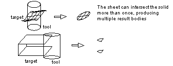
You can subtract like from like, but you can also subtract solids from sheets, and sheets from solids, so long as the sheet cuts the solid completely. If it doesn't, PK_ERROR_non_manifold is returned.

Figure 9-22 Subtracting a sheet body from a solid body

Figure 9-23 Subtracting a solid body from a sheet body
You can intersect solids with solids, as illustrated earlier.
When using more than one tool the resulting intersection is:

Figure 9-24 Intersecting a solid with more than one tool
You can intersect sheets with sheets, so long as the faces have coincident surfaces. The following rules apply when intersecting sheets with sheets:

Figure 9-25 Intersecting sheet bodies that touch but do not overlap

Figure 9-26 Intersecting sheet bodies that have a single overlap

Figure 9-27 Intersecting sheet bodies that have multiple overlaps

Figure 9-28 Intersecting sheet bodies that have opposite face normals
If the faces have crossing surfaces then there is no intersection:

Figure 9-29 Intersecting sheet bodies that cross
You can intersect a sheet with a solid, but not a solid with a sheet.

Figure 9-30 Intersecting a sheet body with a solid body
| Target | Boolean | Tool | Allowed | Fence |
|---|---|---|---|---|
Using a boolean operation to subtract a slot from a block. Face 'A' is split creating the new face 'B' resulting in the both the 'A' and 'B' faces sharing the original surface. Similarly this applies for edges 'C' and 'D' as they have a common direction.

Figure 9-31 Two faces sharing the same surface
In Figure 9-32 face 'E' has the same surface as face '1' and face 'F' has the same surface as face '2'. Therefore, if face '1' and face '2' shared the surface to begin with, then face 'E' and face 'F' share the surface in the result.
After the subtraction boolean faces 'A' and 'B' share the surface of the bottom of the tool, and faces 'C' and 'D' share the surface of the back of the tool since they were created from those surfaces of the tool.

Figure 9-32 Subtracting a tool from a target
|
Note: The edges between faces 'C' / 'E', and 'D' / 'F' (see Figure 9-32) do NOT share a curve even if 'E' and 'F' share a surface. This is because of the dependence of the boolean algorithm on topological boxes; although the new curves are both the intersections of the same two surfaces, the edges are a result of intersections of different faces. |
Figure 9-33 is similar to the previous example except that the target and tool are reversed. In this example the sharing of the surface under faces 'A' and 'B' is determined by the sharing of the surface under faces '1' and '2'; if '1' and '2' share, then so do 'A' and 'B'.

Figure 9-33 Subtracting a tool from a target
The initial stage of the boolean operation is required to generate the sets of imprinted edges and vertices on the target and tool entities. These imprinted edges and vertices form the boundaries of intersection between target and tool entities.
You can create the sets of imprinted edges and vertices on a target and tool entity using PK_BODY_imprint_body and PK_FACE_imprint_faces. These functions create the imprinted edges and vertices on the supplied entities and return the imprinted edges and vertices as paired sets.
The functions receive option structures to control the imprinting process and to supply the imprinting functions with matched topology (in the same format as the boolean option structure).

Figure 9-34 Imprinting a cylindrical tool on a target cube resulting in 4 pairs of imprinted edges
Once a set of edges and vertices has been imprinted on a target and tool body, it is possible to identify which facesets (on both the target and tool) would survive a boolean operation.
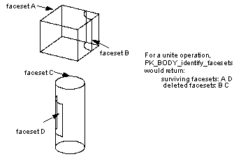
PK_BODY_identify_facesets receives loops of coincident edges, points of contact and a boolean operation (unite, subtract and intersect) and then calculates which facesets would survive the operation and which facesets would be deleted. The loops of coincident edges and points of contact would typically be obtained via calls to the imprinting functions, PK_BODY_imprint_body and PK_FACE_imprint_faces.

Figure 9-35 Simulating a unite operation based on imprinted edges from Figure 9-34
Clash detection supporting clearance analysis is managed by PK_TOPOL_clash. This function receives two sets of topologies, and can detect clashes between:
PK_TOPOL_clash detects and distinguishes:
Options available with this clash detection function for controlling the output are:
| Option | Description |
|---|---|
find_all |
If PK_LOGICAL_true, find all the clashes between the two topologies. If PK_LOGICAL_false, stop after the first clash. (Default: PK_LOGICAL_false) |
find_intersect |
If PK_LOGICAL_true, classify each clash between the two topologies, and return the information in the |
Face clashes can go undetected in either of the following situations:
| <<< Checking | Chapters | Instancing and Patterning >>> |