Surfacing Techniques
Covering
Covering Component
The Covering Component (COVR), contains code for generating a sheet from a closed set of wires. Covering is a surfacing method to fit a surface over the boundary defined with a closed and connected circuit of curves.
Covering fits a surface over a closed loop of curves (wires). All the boundaries must be specified. For each wire in the wire body, an attempt is made to calculate a surface which contains all of the edges of the wire. A face is created and the coedges of the wire are made into loops in the face. If a surface can be calculated, it is used for the geometry of the face.
You can also create a sheet body having a single planar face by forming co-planar wires into loops, and forming the loops into the planar face.
There are two distinct methods and goals with covering. One is to cover a wire body that has no associated face or surface information. The second is to cover an opening in a sheet body. This is done by searching the sheet body for a circuit of connected edges that have no adjacent faces (an open "end"), and covering this circuit of edges.
COVR can also generate a two-sided face from a sheet body. Only sheets with single external loops can be fitted with a NURBS surface, provided that they contain only three or four edges.
The following figure is an example of covering a non-planar wire.
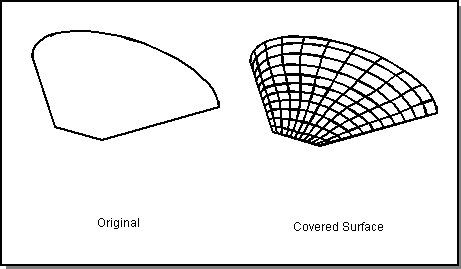
Figure. Covering
The given body must be composed of one or more wires, each wire a simple circuit of wire edges. The edges may have been constructed either directly or by slicing. To obtain suitable circuits from slicing, the slicing must be performed by a single face that is not coincident with any face of the body being sliced. Also, edges of the face cannot coincide with edges of the body being sliced. G1 edges can also be combined to make a single edge, and a non-regularized unite can be performed on a list of edges to create a wire body.
Covering, skinning, lofting, and net surfaces are related techniques for creating a surface from a wireframe or group of edges.
Advanced Covering Component
The Advanced Covering functionality, in the ADM directory, is used to cover (that is, fit a surface onto) circuits in solid or wire bodies. Example uses include end capping, post-translation corrections, and surface definition from curve data. Refer to the following figure.
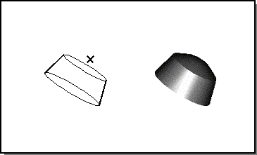
Figure. Covering with Advanced Covering
Some of the advanced features of Advanced Covering include:
- Nonplanar, n-sided boundaries (must be plane-projectable)
- Position (G0) and tangent (G1) continuity with adjacent surfaces
- Boundary continuity can be individually specified on each edge
- Auxiliary point and curve constraints (G0 only)
- Post-covering gap reporting (diagnostics)
- Initial surface can be specified
- Existing surfaces can be re-covered
Advanced Covering Component contains the following:
- Advanced Covering Interface
- Some Advanced Covering Terminology
- Basic Steps for Using Advanced Covering
- General Advanced Covering Algorithm
- Guide and Circuit (Constraint) Layout
- Advanced Covering Limitations
Skinning and Lofting
Skinning fits a surface through a series of disjoint curves (wire bodies), creating a sheet body or a solid body. The solid body can be open or closed, depending on the curves used as input. Refer to the following figure.
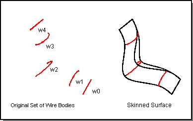
Figure. Skinning
Lofting starts with a surface and fits another surface through a coedge of the original surface and a series of curves (coedges). Lofting takes into consideration the tangents from the original surface at the first coedge and last curve. Laws may be used for lofting. Refer to the following figure.
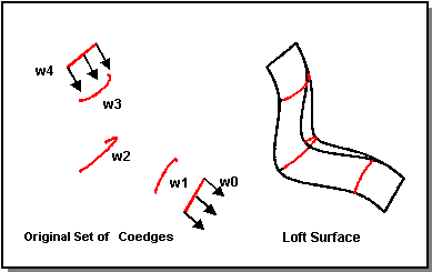
Figure. Lofting
Advanced Surfacing
The Advanced Surfacing Component (AS), provides techniques for creating 2D geometry (a surface or face) by interpolating a sequence of 1D geometry (edges, coedges or wires), arbitrarily positioned in model space. Skinning, lofting, and net surfaces are specifically Advanced Surfacing techniques. Refer to the following sections for an in-depth discussion about these techniques.
Topics include:
- Lofting
- Skinning
- Skinning and Lofting Options
- Interactive Interface
- Journaling for Skinning and Lofting
- Net Surfaces
- Lateral Edge Tangency in Skinning and Lofting
(Covering, which creates a surface from a closed loop of edges, is another type of surfacing technique. This functionality is provided in the Covering Component.)
Deformable Modeling
The basic use of deformable modeling is to construct a curve or surface, apply constraints and loads, and then update the shape's control point set to satisfy the constraints, respond to the loads, and remain fair. Advanced features of the library support local and global deformations as well as deformations away from a default shape. The intended use of the library is to support interactive mouse based manipulations of the free form shape. Features are included in the library to support mouse based picking and dragging. An example mouse interface is provided, written for the Scheme AIDE environment, that supports editing shapes by adding and manipulating constraints and loads.
ACIS Deformable Modeling
ACIS Deformable Modeling Component (ADM) is an interactive sculpting tool for defining fair, free form curves and surfaces. The advantages of ACIS Deformable Modeling include user leverage and automated constraint enforcement. Typically, free form shapes are described by a large set of control point locations. With ACIS Deformable Modeling, users can edit free form shapes by manipulating a small set of parameters which, in turn, cause the deformable modeling algorithm to modify the set of control point locations. Additionally, while manipulating the control point locations, the deformable modeling algorithm simultaneously selects control point locations to automatically enforce a wide variety of design constraints. ACIS Deformable Modeling provides an alternative to control point manipulation for curve and surface design.
Topics include:
- ACIS Deformable Modeling Libraries
- Data Management
- Deformations at Curve Constraint Corners
- Scheme Language Extension Concepts
- Scheme Demonstration Files
- Sculpting
Standalone Deformable Modeling
Standalone Deformable Modeling (DS) is a self-contained C++ component (library) designed to enhance an existing geometry kernel with deformable modeling capabilities. The standalone deformable modeling library is not intended to be used as a standalone geometry kernel. This library depends upon an external geometry kernel for application functions such as persistence and rollback and for some simple intersection and evaluation functions.
A deformable model (sometimes abbreviated "dmod" in the code) refers to the geometry to be deformed. Deformable models can be splines, surfaces, or curves. Deformable models are modified by applying behaviors, such as loads, to domains in the model. Each time a behavior changes, the deformable model is solved for a new shape.
Topics include:
- Deformable Modeling Library Overview
- How to Use Deformable Modeling
- Deformable Models
- Behaviors
- Tags and Tag Objects
- Engineering Issues
- Limitations
- Standalone Deformable Modeling Library
- Standalone Deformable Modeling Interface
- Using Journal Files
Sweeping
The Sweeping Component (SWP), creates solid or sheet bodies by sweeping a profile, or shape, along a path. A profile can be an edge, a face, a wire body, or a planar sheet body (with non-adjacent faces). Profiles can be swept along a distance, around an axis, along a vector, or along an edge or a wire body. The best results are obtained when the profile is swept along an edge or wire body.
The sweep options allow additional control over sweeping behavior. Sweep options, explained in the following pages enable drafting, twisting, and other advanced behaviors. Laws may be used for sweeping.
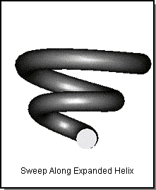
Figure. Sweeping
Topics include:
- Sweeping Basics
- Sweeping with Options
- Self-intersecting Checks in Sweeping
- Rails, Vector Fields, and Hedgehogs
- Feature Naming
- C++ Examples Using Sweeping
[Top]
© 1989-2007 Spatial Corp., a Dassault Systèmes company. All rights reserved.