Net Surfaces
Net surfacing is an advanced surfacing technique that uses a network of curves defining both the u and v surface parameter directions (often called "bi-directional" curves because of this), unlike skinning and lofting which only take curves defining the u parameter. This allows a large degree of control over the final shape of the surface. In other words, net surfaces stretches a surface across a "grid" of curves, and supports curve directional alignment and simplification to a plane, when appropriate. A net surface can handle wires with multiple coedges that have a G1 connection.
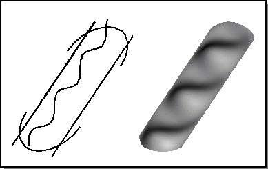
For net surfacing, the input curves are provided in the form of wire bodies. There must be at least four wire bodies, two in each direction. These wires define the cross sections to be interpolated by the resulting sheet body (refer to following figure).

Figure. Net Surface
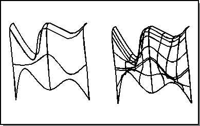
If all of the curves intersect, then the surface passes through the curves and their intersections. If any of the u curves of the net do not intersect all of v curves at some point, the intersection is interpolated. The maximum distance for the interpolation is governed by a tolerance argument to the api_net_wires. The default for this tolerance value is SPAresfit. If the tolerance is changed, a net surface can be created as long as the distance between u curves or between v curves (for example, in the skin direction) is larger than the tolerance intersection distance between a u curve and a v curve. Thus, the curve interpolating accuracy of the net surface is controlled by the user's accuracy of the intersections of the cross sections. Refer to the following figure for an illustration of net wires.

Figure. Net Wires
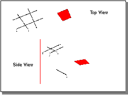
Curves in the resulting surface that extend beyond the intersections are trimmed. However, shorter curves are not extended to meet the intersection points. The original curves are not altered, but the surface defined from the net surface is bounded by the trimmed curves, as shown in the following figure. This also illustrates interpolation. In this example, line 4 is not in the same plane as lines 1, 2, and 3 and does not intersect them, so the resulting surface is placed in between the two planes. (The offset is exaggerated for effect.)

Figure. Net Surface Interpolation and Trimming
The api_net_wires function creates the network surface. It requires the number of wires in the u direction, a pointer to the first wire body in the u list, the number of wires in the v direction, a pointer to the first wire body in the v list, an address for the resulting surface body, and flags for alignment and simplification.
The optional argument for align_directions specifies whether or not to line up the directions of the curves in both the u and v directions listed in the body_list. When this option is on, the directions of open and closed curves in the u or v direction are changed to line up with the first curves in the given direction. After all of the curves in the u and v directions are aligned, the order and directions of the v curves are modified to insure the proper surface parameter orientation. This insures that the start of the first v curve intersects the start of the first u curve. The start of the curve in the v direction is changed to be the start of the curve in the u direction.
The optional argument simplify specifies whether or not to simplify the resulting surface geometry. If appropriate, the result is a planar surface bounded by the first and last uv wires.
[Top]
© 1989-2007 Spatial Corp., a Dassault Systèmes company. All rights reserved.