Skinning and Lofting Options
A number of options are available with lofting to control the edge parameterization, twist minimization, coedge direction alignment, take-off vector direction, conic simplification and creation of a solid body. The skinning and lofting optional arguments have the following default values:
| Optional Argument | Default |
| arc_length | false |
| twist | true |
| align direction | true |
| perpendicular | false |
| simplify | true |
| closed | false |
| solid | true |
| periodic | false |
| virtualGuides | false |
| merge_wirecoedges | true |
| estimate_loft_tanfacs | true |
| match_vertices | true |
| guide_curve_preference | FOLLOW_GUIDE_CONSTRAINT |
| gap_type | SKIN_GAP_EXTENDED |
Arc Length Option
The arc_length option is used to choose arc length or isoparametric parameterization of the skinning/lofting surfaces. In isoparametric parameterization, the surface parameter in the v direction follows the cross section curves. In arc length parameterization, the surface parameter follows lines of constant length. The default is isoparametric parameterization.
Scheme Example
| ; Turn on u_param lines to see different parameterization. (option:set 'u_param 7)v (zoom-all) (define wire_1 (wire-body (list (edge:linear (position 0 0 0) (position 50 0 0))(edge:linear (position 50 0 0) (position 50 50 0)) (edge:linear (position 50 50 0) (position 0 50 0))(edge:linear (position 0 50 0) (position 0 0 0))))) (define wire_2 (wire-body (list (edge:linear (position 0 0 60) (position 50 0 40))(edge:linear (position 50 0 40) (position 50 50 40))(edge:linear (position 50 50 40) (position 0 50 60))(edge:linear (position 0 50 60) (position 0 0 60))))) (define wire_3 (wire-body (list (edge:linear (position 0 0 100) (position 50 0 100))(edge:linear (position 50 0 100) (position 50 50 100))(edge:linear (position 50 50 100) (position 0 50 100))(edge:linear (position 0 50 100) (position 0 0 100))))) ; --- Arc length (define arc_body (sheet:skin-wires (list wire_1 wire_2 wire_3) #t #f #f #f)) (define move1 (entity:move arc_body 100 0 0)) ; --- Iso (define iso_body (sheet:skin-wires (list wire_1 wire_2 wire_3) #f #f #f #f)) (define move2 (entity:move iso_body -100 0 0)) (iso) (zoom-all) |
Example. Using the Arc Length Option
Figure. Using the Arc Length Option
Twist Option
The twist option may be used to minimize the twist of the surface produced. Twist minimization aligns closed curves such that the start of the second curve is aligned to the start of the first curve. Even if a body's shape is unaffected by twisting, a surface with a twist could produce unexpected results when faceting and rendering. The following two figures illustrate twist minimization.
The default is that twist minimization is off, because otherwise the geometry definition of the underlying curves is changed to align the starting positions. Twist minimization is also an involved calculation that some users may not want to have carried out.
Figure. Conceptual Illustration of Twist Minimization
Figure. Twist Minimization, Faceted
Figure. Twist Minimization, Faceted shows an example of skinning between circular and square profiles without twist minimization (upper left) and with twist minimization (lower right).
Scheme Example
| (define loop1 (wire-body (list (edge:circular (position 0 0 0) 10) ))) (define loop2 (wire-body (list (edge:linear (position -10 -10 -5) (position -10 10 -5)) (edge:linear (position -10 10 -5) (position 10 10 -5)) (edge:linear (position 10 10 -5) (position 10 -10 -5)) (edge:linear (position 10 -10 -5) (position -10 -10 -5))))) (define skin (sheet:skin-wires (list loop1 loop2) #t #f #t)) (define skin2 (sheet:2d skin)) ; OUTPUT No Twist (roll -2) (define skin (sheet:skin-wires (list loop1 loop2) #t #t #t)) (define skin2 (sheet:2d skin)) ; OUTPUT Twist |
Example. Twist Minimization, Rendered
Figure. Twist Minimization, Rendered
Align Direction Option
The align direction option may be used to allow the lofting algorithm to align the direction of the wires or coedges in the input list. Refer to the following figure for an example of alignment of open coedges. Closed loops of wires can also be aligned. The default is aligned.
Figure. Align Direction Option
Perpendicular Option
The take-off vector is a tangent vector going out of the starting edge or surface and into the skinned or lofted surface. The perpendicular option (for lofting only) is used to specify the direction of the take-off vector, perpendicular to the coedge or in the loft direction. (This removes any restriction that the take-off vector for the loft has to be determined by the cross-product of the coedge tangent vector and the surface normal times the tangent factor.) The default is in the loft direction, because a perpendicular take-off vector can cause self-intersections to the surface.
Scheme Example
In the following example, body0 is made with the perpendicular option and body1 is made without the perpendicular option.
| (define wire_1 (wire-body (list (edge:linear (position 0 0 0) (position 50 0 0)) (edge:linear (position 50 0 0) (position 50 50 0)) (edge:linear (position 50 50 0) (position 0 50 0)) (edge:linear (position 0 50 0) (position 0 0 0))))) (define wire_2 (wire-body (list (edge:linear (position 100 0 0) (position 150 0 0)) (edge:linear (position 150 0 0) (position 150 50 0)) (edge:linear (position 150 50 0) (position 100 50 0)) (edge:circular-3pt (position 100 50 0) (position 90 25 0) (position 100 0 0))))) (zoom-all) (sheet:planar-wire wire_1) (sheet:planar-wire wire_2) (define coedge1 (list-ref (entity:coedges wire_1) 1)) (define coedge2 (list-ref (entity:coedges wire_2) 3)) (define loft_wire1 (section coedge1 #f 100)) (define loft_wire2 (section coedge2 #t 100)) (define Sect (list loft_wire1 loft_wire2)) (define body0 (sheet:loft-wires Sect #f #t #t #t)) (define body1 (sheet:loft-wires Sect #f #t #t #f)) |
Example. sheet:loft-wires Illustrates Perpendicular vs. Non-Perpendicular
Figure. sheet:loft-wires Illustrates Perpendicular vs. Non-Perpendicular
Simplify Option
The simplify option simplifies the created surface to a conical surface, if applicable. If all of the cross sections lie on a conical surface (plane, cylinder, cone, sphere, or torus), the conical surface is created instead. The SPAresabs variable is used to determine whether or not the cross section lies on an analytical surface (planar, conical, spherical, or toroidal). The default is not simplified.
Closed Option
The closed option may be used when the user needs to construct a solid body closed in v. A solid body is constructed only when all the wires supplied are closed; otherwise this option is ignored. The default is an open (not closed) body. The following figure shows an example of a closed skin constructed from four profiles. The surface is continuous at each profile.
If the user provides a set of closed profiles, the face normals of the skin or loft body point outside, away from the body material. When the user provides a set of open profiles, the face normals of the skin or loft face are oriented along the surface normals, and no attempt is made to change the face normal orientation.
Scheme Example
| (define loop1 (wire-body (list (edge:linear (position -20 0 0)(position -20 0 5)) (edge:linear (position -20 0 5)(position -15 0 5)) (edge:linear (position -15 0 5)(position -15 0 0)) (edge:linear (position -15 0 0)(position -20 0 0))))) (define loop2 (wire-body (list (edge:linear (position 0 -20 0)(position 0 -20 5)) (edge:linear (position 0 -20 5)(position 0 -15 5)) (edge:linear (position 0 -15 5)(position 0 -15 0)) (edge:linear (position 0 -15 0)(position 0 -20 0))))) (define loop3 (wire-body (list (edge:linear (position 20 0 0)(position 17.5 0 5)) (edge:linear (position 17.5 0 5)(position 15 0 0)) (edge:linear (position 15 0 0)(position 20 0 0))))) (define loop4 (wire-body (list (edge:linear (position 0 20 0)(position 0 17.5 5)) (edge:linear (position 0 17.5 5)(position 0 15 0)) (edge:linear (position 0 15 0)(position 0 20 0))))) ; OUTPUT Original (define skin (sheet:skin-wires (list loop1 loop2 loop3 loop4) #t #t #t #f #t #t)) ; OUTPUT Result |
Example. Skinned Closed Body
Figure. Skinned Closed Body
Periodic Option
The periodic option allows constructing loft bodies that are periodic in v. This implies that the loft bodies close back on themselves smoothly (continuously) at the start and end profiles. Setting the closed flag with a value equal to 2 in the skinning APIs activates the periodic option.
In Scheme, the periodic flag is set to #t to achieve the same effect. At least three profiles must be supplied to create a periodic loft body. For example, the periodic skin surface may be constructed from the same set of four profiles used in the preceding example.
Scheme Example
| (define loop1 (wire-body (list (edge:linear (position -20 0 0)(position -20 0 5)) (edge:linear (position -20 0 5)(position -15 0 5)) (edge:linear (position -15 0 5)(position -15 0 0)) (edge:linear (position -15 0 0)(position -20 0 0))))) (define loop2 (wire-body (list (edge:linear (position 0 -20 0)(position 0 -20 5)) (edge:linear (position 0 -20 5)(position 0 -15 5)) (edge:linear (position 0 -15 5)(position 0 -15 0)) (edge:linear (position 0 -15 0)(position 0 -20 0))))) (define loop3 (wire-body (list (edge:linear (position 20 0 0)(position 17.5 0 5)) (edge:linear (position 17.5 0 5)(position 15 0 0)) (edge:linear (position 15 0 0)(position 20 0 0)) ))) (define loop4 (wire-body (list (edge:linear (position 0 20 0)(position 0 17.5 5)) (edge:linear (position 0 17.5 5)(position 0 15 0)) (edge:linear (position 0 15 0)(position 0 20 0))))) ; Options: arcwise #t; minimize_twist #t; align_directions #t; ; simplify #t; closed #f; solid #f; periodic #t (define skin (sheet:skin-wires (list loop1 loop2 loop3 loop4) #t #t #t #f #f #f #t)) |
Example. Using the Periodic Option
Virtual Guides
Refer to the topic Skinning with Virtual Guide Curves.
Solid Option
The solid option may be used when a solid skin or loft must be constructed but a closed body is not desired. When a closed body is not desired, the end wires are capped with planar faces. The end face normals are oriented away from (outside) the resulting body. The default is a solid body. The following figure shows an example of a set of profiles using the solid option instead of the closed option.
If the user provides a set of closed profiles, the face normals of the skin or loft body point outside, away from the body material. When the user provides a set of open profiles, the face normals of the skin or loft face are oriented along the surface normals, and no attempt is made to change the face normal orientation.
Scheme Example
| (define loop1 (wire-body (list (edge:linear (position -20 0 0)(position -20 0 5)) (edge:linear (position -20 0 5)(position -15 0 5)) (edge:linear (position -15 0 5)(position -15 0 0)) (edge:linear (position -15 0 0)(position -20 0 0))))) (define loop2 (wire-body (list (edge:linear (position 0 -20 0)(position 0 -20 5)) (edge:linear (position 0 -20 5)(position 0 -15 5)) (edge:linear (position 0 -15 5)(position 0 -15 0)) (edge:linear (position 0 -15 0)(position 0 -20 0))))) (define loop3 (wire-body (list (edge:linear (position 20 0 0)(position 17.5 0 5)) (edge:linear (position 17.5 0 5)(position 15 0 0)) (edge:linear (position 15 0 0)(position 20 0 0))))) (define loop4 (wire-body (list (edge:linear (position 0 20 0)(position 0 17.5 5)) (edge:linear (position 0 17.5 5)(position 0 15 0)) (edge:linear (position 0 15 0)(position 0 20 0))))) ; OUTPUT Original (define skin (sheet:skin-wires (list loop1 loop2 loop3 loop4) #t #t #t #f #f #t)) ; OUTPUT Result |
Example. Skinned Solid Body

Figure. Skinned Solid Body
The merge_wirecoedges option may be used to merge G1 vertices of the skinning and lofting wire profiles. This improves operations such as blending and shelling since it reduces the coedge/edge count, which reduces the number of surfaces and eliminates near tangent edges.
Note: This option replaces the global option of the same name in versions 7.0 and later.
Match Vertices Option
The match_vertices option (when FALSE) suppresses the vertex matching algorithm which ensures that all profiles consist of the same number of coedges. A heuristic approach is used to determine which vertex pairs are good matches. Profile coedges are then split where additional vertices are needed. If you have an equal number of edges per skinning profile and do not wish to have any change in topology than set this option to FALSE. However, this option will be forced to TRUE if the coedge numbers of the profiles are not equal. Its default is TRUE.
Note: This option replaces the global options match_corners and align_corners in versions 7.0 and later.
Loft Estimate Tangent Factors Option
If desired, the option loft_estimate_tanfacs can be set, which invokes an algorithm that finds an optimum factor to scale the weight for the tangent factors based on a minimum radius of curvature of the lofted body as a whole. This not only helps to create more pleasing surfaces but insures greater ability to shell and blend lofted models. If you set this option to TRUE, the user-supplied weight values in each Loft_Connected_Coedge_List are then scaled by the optimum scale factor found.
Note: This option replaces the global option of the same name in versions 7.0 and later).
Guide Curve Preference Option
The guide preference option is an enumerated type with two possible values, FOLLOW_GUIDE_CONSTRAINT and FOLLOW_TANGENT_CONSTRAINT. This option is used to specify how an over constrained guide is resolved. If the type FOLLOW_GUIDE_CONSTRAINT is set, then the resulting lofting surface will always stay with the defining guide curve. If the FOLLOW_TANGENT_CONSTRAINT is specified, then the lofting surface will always follow the tangent constraint. Default is FOLLOW_GUIDE_CONSTRAINT.
Gap Type Option
The gap_type option specifies how to fill a gap that may occur between two lateral faces in a lofting or skinning with draft operation.
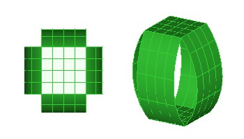
Figure. Skin with Draft Operation with Gaps
There are three options to fill the gaps:
- SKIN_GAP_EXTENDED
-
The lateral surfaces extend naturally until they intersect and produce a
lateral edge. This is the recommended and default behavior.
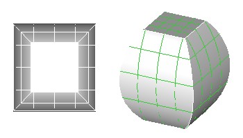
Figure. Extended Gap
- SKIN_GAP_CHAMFERED
-
Skinning constructs a linear surface that connects the two lateral faces. This
is a ruled type surface.
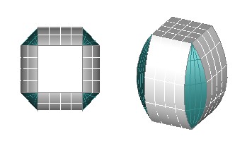
Figure. Chamfered Gap
- SKIN_GAP_ROUNDED
-
Skinning constructs a surface that is tangential to the two lateral faces.
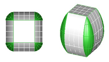
Figure. Rounded Gap
Presently, the gap type options "rounded" and "chamfered" are available only when there are two profile curves specified for skinning. If more than two profile curves are specified, then the gap_type (if different from "extended") is changed to "extended" and a warning is issued.
[Top]
© 1989-2007 Spatial Corp., a Dassault Systèmes company. All rights reserved.