Skinning
Skinning fits a surface through a series of curves. The skinned surface is a two-parameter function (u,v); the curves provide the u parameter of the surface and the skin surface algorithm defines the v parameter (refer to the following figure). It is a precise surface and does not have C1/G1 discontinuities. ACIS can make a skin surface between any numbers of curves. The surface allows a take-off vector field to be placed on each of the curves, forcing a tangent constraint on that surface at that curve cross section. Although tangent constraints are more often associated with lofting, skinning allows constraints to be placed on profiles in several indirect ways.
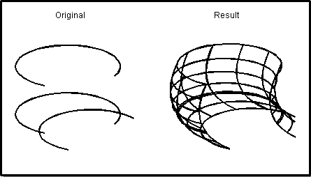
Figure. ACIS Skin Surface
The curves used as input to skinning are given in terms of wire bodies and hence may contain more than one edge (curve) per body. In this case, and for lofting, edges are aligned (with the possibility of splitting edges) and a series of surfaces are made. The resulting sheet body consists of one or more faces linked together to form a shell or solid.
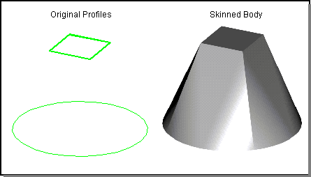
Figure. Skinning Profiles with Differing Numbers of Edges
Skinning and lofting are very similar techniques. However, in ACIS, two distinctions exist: skinning takes wire bodies as input and allows control over tangent constraints in indirect ways. Lofting takes coedges as input and allows direct control over tangent constraints. Skinning and lofting are related historically in the industry and in their ACIS implementations. Skinning is often used as a newer term for lofting, although ACIS maintains a distinction between the two operations.
The Advanced Surfacing Component provides eight functional variations of skinning, differing by methods of surface control:
- Basic skinning
- Skinning with a path
- Skinning with a draft angle
- Skinning to the planar normal
- Skinning with guide curves
- Skinning with virtual guide curves
- Skinning with ruled surfaces
- Multi-stem skinning
Each of these is explained in detail in the sections below.
In general, skinning provides options to support the following:
- Surface isoparametric or arc length parameterization
- Alignment of the direction of the cross section curves so that they are in the same direction as the first curve
- Twist and non-twist minimization
- Simplification of the created surface to a conical surface, if applicable
- Creation of a closed body
- Creation of a solid body
Each of these is explained in detail in the relevant section.
Skinning Parameters
A skinning operation requires three basic categories of parameters (arguments). The first category defines the wire body profiles to be skinned. The second category defines the type or method of the skinning operation to be performed (for example, skinning with guides, and skinning with a path). The third category contains optional parameters to control what type of object is formed as a result of the skinning operation (for example, closed and solid).
api_skin_wires (profiles, guides or paths, skinning options)
Profiles
The profiles used for skinning are given as an array of wire bodies. There must be at least two wires. If a closed solid body is required, at least three distinct wire profiles must be provided. If the first and last profiles are identical, a closed solid skinned body is automatically constructed. Wires can be open or closed but the entire wire list must be all open or all closed. They must be simple loops if closed and in all cases, not self-intersecting. Additionally, the first and last wires in a skin surface may be points (a point in ACIS is represented by a vertex wire). For example, skinning between a point and a circular arc will give a spline cone with the point being the apex.
Guides, Paths, and Draft Conditions
C++ Data Structures: skinning_normals
The second category defines the type of skinning operation to be performed. In the case of simple skinning there are no arguments for this category. However for skinning with guides, a list of one or more edges is required. For skinning with a path, an additional wire body is required. For skinning with a draft angle, two angles and magnitudes are required. For skinning with planar normal constraints, the enumerated type skinning_normals is required. api_skin_wires is overloaded to handle all the different permutations of input.
Options
C++ Data Structures: skinning_options
The main skinning API also takes options to control surface parameterization, wire twist, wire direction, simplification, and creation of a solid or closed body. Although different types of skinning accept different options, all options maintain the same principle and purpose across the type variations. The options can be passed in individually as a series of flags or consolidated in the class skin_options. See Skinning and Lofting Options for more information.
Functional Variations of Skinning
The following examples demonstrate the functional variations of skinning. Starting with the same original profiles, applying the different methods of surface control produces very different results.
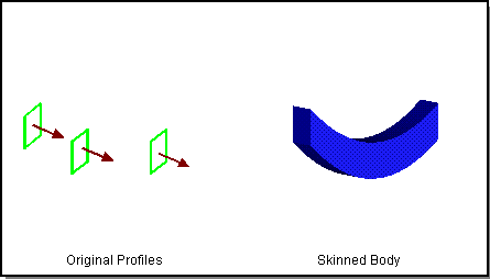
Figure. Basic Skinning
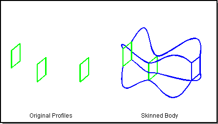
Figure. Skinning with Draft Angles
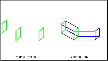
Figure. Ruled Skinning
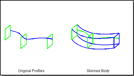
Figure. Skinning with Guide Curves
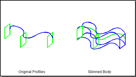
Figure. Skinning with Virtual Guide Curves
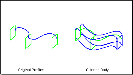
Figure. Skinning with Paths
Basic Skinning
Scheme Extensions: sheet:skin-wires
C++ APIs: api_skin_wires
Skinning Options: arc_length, no twist, minimize twist, simplify, closed, solid, periodic
Basic skinning fits a surface through a series of curves. In this case the skinning algorithm computes the take-off vector field going into and out of the wire bodies. If only two wires are given, the resulting surface is ruled.
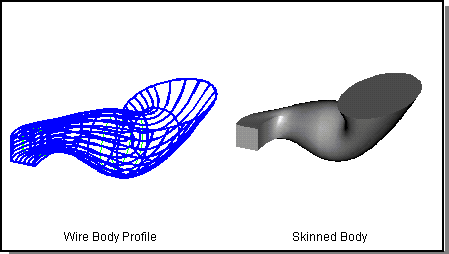
Figure. Basic Skinning
Skinning with Guide Curves
Scheme Extensions: sheet:skin-wires-guides
C++ APIs: api_skin_wires
Skinning Options: arc_length, no twist, minimize twist, closed, solid, periodic, simplify, virtualGuides
Skinning with guide curves is a method of locally controlling the shape of the v parameter direction of the skin surface in between the input wires. In a typical skinning operation, the user creates two or more wire bodies and a surface is fitted between them. When skinning with a guide curve, one or more 3-space curves can be specified between the skinning profiles, and the surface will follow the guide curves. The surface will be C1 continuous at every point, even across the guide itself.
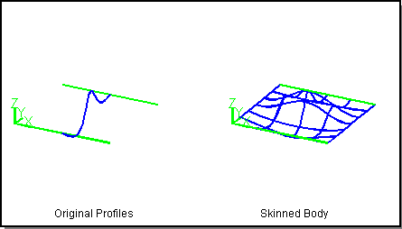
Figure. Skinning with Guide Curve
One or more guide curves can be placed on the skinning profiles.
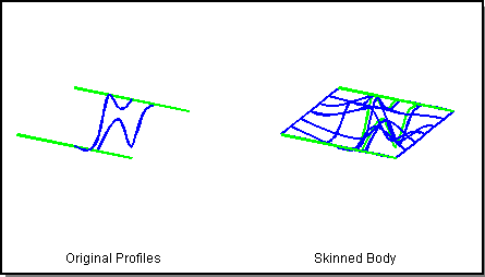
Figure. Skinning with Two Guide Curves
The guide curve is used for local surface control only. It affects the geometry of the surface created between the series of edges to which the curve is attached. No other surfaces are effected (refer to the following figure).
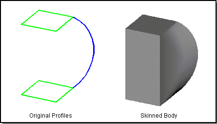
Figure. Guide Curve Affects Only Right-most Surface
If the guide curve passes through the vertices, the surfaces on the two adjoining faces follow the curve profile. In this case, the boundary of the surface extends along the guide and we do not maintain C1 continuity.
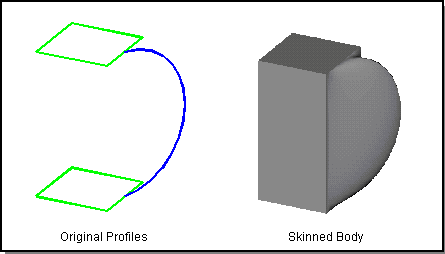
Figure. Guide Curve Affects Right and Front Surfaces
Considerations on input of guide curves:
- The guide curves must contact (within SPAresabs) each profile in the skinning list
- The guide curves must start and end on the first and last guide curves respectively
- Any number of guide curves can be added
- The guide curves need not be consistent in the v direction
- The guide curves must be non-looping and well behaved
In addition to surface control, guide curves also implicitly control the breakup of the coedges. If the guide curves intersect vertices on the wire it is guaranteed that those vertices will align. If a guide curve intersects coedges at positions other than vertices, then the adjacent vertices will be aligned (A and B in the following figure).

Figure. Vertices are Automatically Aligned
Skinning with Virtual Guide Curves
Scheme Extensions: sheet:skin-wires-guides
C++ APIs: api_skin_wires
Skinning Options: arc_length, no twist, minimize twist, closed, solid, periodic, simplify, virtualGuides
Virtual guide curves provide the ability to make one guide curve globally affect the skinned surfaces. If one guide curve is added to a list of profiles, ACIS takes that guide curve and propagates it across the profiles to each edge vertex. This effectively changes guide curves from local surface control to global surface control. This flag is false by default, but can be set to true in the call to the function api_skin_wires.
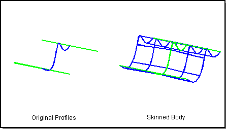
Figure. Virtual Guide Curves
One or more guide curves can be placed on the wire profiles. In this case, the guide curve closest to the edge is propagated to each edge vertex.
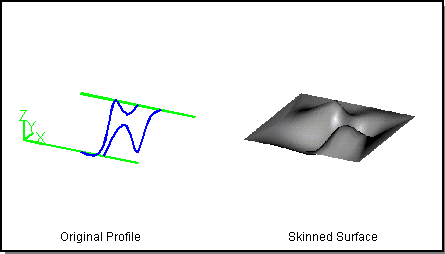
Figure. Virtual Guide Curves with Two User-defined Curves
If a wire vertex has two neighboring user-defined guide curves, the two curves are blended together at the vertex.
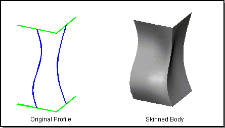
Figure. Virtual Guide Curves with Two User-defined Curves
Skinning with Draft Angles
Scheme Extensions: sheet:skin-wires-draft
C++ APIs: api_skin_wires
Skinning Options: arc_length, no twist, minimize twist, solid
Skinning with draft angles provides the ability to control the take-off vectors of the two outer skinning profiles. The draft angle is defined as an angle off the plane of the wire at every point along the skinning profile. In addition to the user supplying the angle itself, one may also supply a magnitude for the take-off vector.
The draft angle and magnitude is constant for the entire profile. However, one may apply different draft angles to the two outer profiles. In addition skinning with draft angles supports open and closed profiles and skinning to a point. When skinning to a point, the algorithm constructs its own normal vector. The outer profiles must be planar when not degenerate.
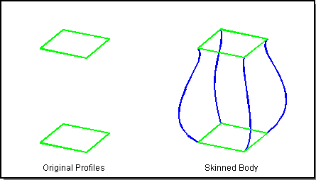
Figure. Skinning with Draft Angles
Skinning to the Planar Normal
Scheme Extensions: sheet:skin-wires-normal
C++ APIs: api_skin_wires
C++ Data Structures: skinning_normals
Skinning Options: arc_length, no twist, minimize twist, closed, solid, periodic
Skinning to the planar normal provides the ability to constrain the take-off vectors on each profile to the profile's normal. All profiles must be planar and non-degenerate.
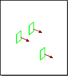
Figure. Skinning to Planar Normal
As input, api_skin_wires takes the enumerated type skinning_normals containing the following constants:
- LAST_NORMAL
- constrain only the last profile
- FIRST_NORMAL
- constrain only the first profile
- ENDS_NORMAL
- constrain the first and last profile
- ALL_NORMAL
- constrain all the profiles
Skinning to the planar normal does not allow control of the magnitude of the take-off vectors; rather, it determines the magnitudes that yield surfaces with the maximum minimum radius of curvature.
Ruled Skinning
Scheme Extensions: sheet:skin-wires-ruled
C++ APIs: api_skin_wires
Skinning Options: arc_length, no twist, minimize twist, simplify, closed, solid
Ruled skinning provides the ability to skin a series of three or more profiles by placing ruled surfaces in between each section of profiles. If only two profiles are provided, this command defaults to basic skinning; and generates a ruled surface in between the two profiles.
Ruled skinning works with both closed and open profiles, degenerate end points, and the solid and closed options. However, it is possible in many closed situations to have surfaces that intersect each other. No check is made for that case.
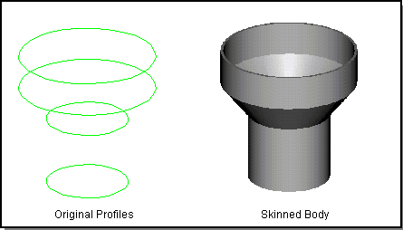
Figure. Ruled Skinning
Skinning with Paths
Scheme Extensions: sheet:skin-wires
C++ APIs: api_skin_wires
Skinning Options: arc_length, no twist, minimize twist, simplify, closed, solid
Skinning with a path provides the ability to constrain the take-off vectors on each profile based on a path curve. The resulting surface does not follow the path exactly; rather a constant vector field is placed on each profile. The vector is defined as the tangent vector of the path curve at the point in which the curve intersects the profile's plane.
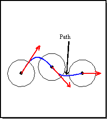
Figure. Take-Off Vector Used in Skin with Path
Only one path can be used and it must be a well behaved curve.
Branched Skinning
Scheme Extensions: sheet:skin-wires-branch
C++ APIs: api_skin-wires
C++ Data Structures: skinning_normals
Skinning Options: arc_length, align direction, minimize twist, solid
Branched skinning provides the ability to skin multiple profile paths. The user first specifies a profile path for the trunk of the skin, consisting of one or more wires.They can then specify two or more branches (each of one or more wires) which the skin body will follow.
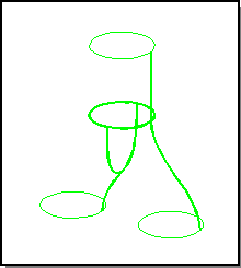
Figure. Branched Skinning
Unlike regular skinning, the order of the wires in the profile list(s) is important. The last profile in the trunk will be the end to which the branches attach. The first profile of each of the branches will be the end which they attach to the trunk.
In addition to the standard options, the user may also specify "normal" conditions similar to the command "skinning to the planar normal". However, in all cases, the normal condition will always be imposed on the last wire of the trunk. This guarantees a C1 continuity between the trunk and the branches.
The wire profiles may be open or closed and must be planar.
Scheme Example
| (define wire1 (wire-body (list (edge:circular (position 0 0 70) 30 0 360)))) (define wire2 (wire-body (list (edge:circular (position 0 0 0) 30 0 360)))) (define wire3 (wire-body (list (edge:circular (position -50 0 -100) 30 0 360)))) (define wire4 (wire-body (list (edge:circular (position 50 0 -100) 30 0 360)))) (define body (sheet:skin-wires-tree (list wire1 wire2) (list wire3) (list wire4))) |
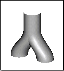
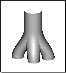
Figure. Branched Skinning
[Top]
© 1989-2007 Spatial Corp., a Dassault Systèmes company. All rights reserved.