Scheme Extensions Aa thru Sk
|
|
|
|
Technical Article
|
| Scheme is a public domain programming language, based on the LISP language,
that uses an interpreter to run commands. ACIS provides extensions (written in
C++) to the native Scheme language that can be used by an application to
interact with ACIS through its Scheme Interpreter. The C++ source files for
ACIS Scheme extensions are provided with the product. Spatials Scheme based
demonstration application, Scheme ACIS Interface Driver Extension (Scheme
AIDE), also uses these Scheme extensions and the Scheme Interpreter.
|
face:get-loft-laws
- Action
-
Returns the laws of the surface on which the selected face lies.
-
Filename
-
scm/scmext/skin/skin_scm.cpp
-
APIs
-
api_str_to_law
-
Syntax
-
(face:get-loft-laws entity)
-
Arg Types
-
-
Returns
-
section
Description
This extension uses a face as an input argument to retrieve the underlying laws
for the surface on which the face lies.
This extension is a two-step process with running the
face:get-loft-laws
extension
as the first step followed by selecting the face for which you want the law
information. No information is returned until a face is selected. Notice the
mouse pointer becomes a cross-over-diamond shape when this extension has been
generated and is waiting for a face to be selected. To select a face, position
and select/click the mouse pointer on that face.
Returns an error if the face selected has no laws defined or is not a
skin_spl_surface.
- Arguments
-
entity
is an input argument and can be any of the scheme entities.
; face:get-loft-laws
; Define a point to loft to.
(define pnt (wire-body:points (position 0 0 30)))
;; pnt
; Get the coedges off that point.
(define cl1 (entity:coedges pnt))
;; cl1
; Define a block to loft from.
(define blk (solid:block (position -20 -20 0)
(position 20 20 10)))
;; blk
; Get the coedges off the block.
(define cl2 (entity:coedges blk))
;; cl2
; Define a law for the point.
(define lawa (law "vec(cos(t),sin(t),0)"))
;; lawa
(define dom0 (law "domain(law1,law2,law3)" lawa
(law:eval "0.0") (law:eval "2.0*Pi")))
;; dom0
; Make a section data structure for the point, its
; coedges, and its law.
(define sec1 (section cl1 (list dom0) #f 20))
;; sec1
; Make a section data structure for the block; this
; has no explicit laws.
(define sec2 (section (list (list-ref cl2 1)
(list-ref cl2 3) (list-ref cl2 5)
(list-ref cl2 7)) #f -1 #f))
;; sec2
; Loft the sections.
(define loft (sheet:loft-wires
(list sec1 sec2) #f #t #t)) (sheet:2d loft)
;; loft
; Get the law from the lofted face.
; This extension has two steps: run the
; face:get-loft-laws extension and select the face
; for which you want the law information. (No
; information is returned until a face is selected.
; To select a face, position and select/click the
; mouse pointer on that face. Notice the mouse
; pointer becomes a cross-over-diamond shape when
; this extension has been generated and is waiting
; for a face to be selected.
(define law-list (face:get-loft-laws (pick-face)))
; There is no return until a face is selected.
; Mouse-select a face.
;; law-list |
[Top]
section
- Action
-
Creates a data structure used as input to the sheet:loft-wires
extension.
-
Filename
-
scm/scmext/skin/skin_scm.cpp
-
APIs
-
None
-
Syntax
-
(section coedges [laws] in-flag take-off-factor
[no-loop-flag=#f] [ao]) -
Arg Types
-
-
Returns
-
section
Description
The section Scheme data type creates a data structure used as input to the
sheet:loft-wires extension.
- Arguments
-
coedges
argument is a list of one or more coedges to be used as one section of the loft
operation. Only one coedge of a loop has to be specified when the argument
no-loop-flag
is set to #f; all other coedges connected with the given coedges in one or more
loops are added to the list.
-
laws
is an input list of laws.
in-flag
argument specifies whether the take-off
SPAvector is coming into (#t) or out of (#f) the given coedge.
Typically, the first section has its coedges labeled as out of (#f) and all
others sections created for the loft operation label their coedges in the list
as into (#t).
-
take-off-factor
is applied to the magnitude of the take-off
SPAvector, and can be used to control the shape of the loft
surface. The "take-off"
SPAvector
is a tangent
SPAvector
going out of a given surface and into the lofted surface. The lofted surface is
always tangent to the surface bounded by the coedges. Small values for the
weighting of the take-off
SPAvector
mean that the transition from the tangent to the lofted surface happen
abruptly. Large values for the weighting of the take-off
SPAvector
mean that the transition from the tangent to the lofted surface happen more
gradually. Extremely high weight values could result in excessive whipping in
the lofted surface, if not a self-intersecting surface.
-
The option argument
no-loop-flag
is set to #f by default. This means that only one coedge of a loop has to be
specified; all other coedges connected with the given coedge are automatically
added to the list. When the no-loop-flag is set to #t, it means that only the
specified coedges in coedges are to be used as that part of the section; no
connecting loop coedges are added to the list.
-
acis-opts, which contain versioning and
journaling parameters, must be the last argument, if stated.
[Top]
sheet:loft-wires
- Action
-
Creates a sheet body that lofts sections (faces) or a series of wires.
-
Filename
-
scm/scmext/skin/skin_scm.cpp
-
APIs
-
api_loft_coedges
-
Syntax
-
(sheet:loft-wires section-list [options] [ao])
-
Arg Types
-
-
Returns
-
body
Description
The
sheet:loft-wires
extension is similar to the sheet:skin-wires extension, except in this case one
of the input curves has a surface attached. The resulting surface that is
skinned across the wireframe bodies is constrained to be tangential to the
input surface at the boundary.
If two section inputs used as arguments into the sheet:loft-wires extension
are relatively close to one another and have large values for their
take-off-factor
SPAvector magnitudes, the lofted surface may have some
undesirable anomalies. These anomalies can be removed by recreating the
sections with adjusted (smaller) take-off-factor values. Small values for the
weighting of the take-off vectors mean the transition from the tangent to the
lofted surface happen abruptly. Large values for the weighting of the take-off
SPAvector
mean that the transition from the tangent to the lofted surface happen more
gradually. Extremely high weight values could result in excessive whipping in
the lofted surface, if not a self-intersecting surface.
- Arguments
-
section-list
gives the information of all the sections.
-
skin-options
is the different options provided. For a complete list of skinning options,
please refer to the skin:options documentation.
-
acis-opts, which contain versioning and
journaling parameters, must be the last argument, if stated.
- Limitations
-
For the perpendicular option (set to #t) to work properly, the perpendicular
take-off vectors from the defining coedge cannot intersect.
[Top]
sheet:loft-wires-guides
- Action
-
Creates a sheet body that lofts sections (faces) or a series of wires following
guide constraints.
-
Filename
-
scm/scmext/skin/skin_scm.cpp
-
APIs
-
api_loft_coedges
-
Syntax
-
(sheet:loft-wires-guides section-list guide-list [skin-options][acis-opts])
-
Arg Types
-
-
Returns
-
body
Description
The
sheet:loft-wires-guides
extension is similar to the sheet: sheet:loft-wires
extension, except in this case the surfaces are constrained to the follow the
guide curves. The rules and regulations of the guides follow skinning with
guides.
If two section inputs used as arguments into the sheet:loft-wires
extension are relatively close to one another and have large values for their
take-off-factor vector magnitudes, the lofted surface may have some undesirable
anomalies. These anomalies can be removed by recreating the sections with
adjusted (smaller smaller) take-off-factor values. Small values for the
weighting of the take-off vectors mean the transition from the tangent to the
lofted surface happen abruptly. Large values for the weighting of the take-off
vector mean that the transition from the tangent to the lofted surface happen
more gradually. Extremely high weight values could result in excessive whipping
in the lofted surface, if not a self-intersecting surface.
- Arguments
-
section-list
is a list of sections.
-
guide-list
is an input argument of type edge.
-
skin-options
gives the different options available for skinning. For a complete list of
skinning options, please refer to the skin:options
documentation.
-
acis-opts, which contain versioning and
journaling parameters, must be the last argument, if stated.
- Limitations
-
For the perpendicular option (set to #t) to work properly, the perpendicular
take-off vectors from the defining coedge cannot intersect.
; sheet:loft-wires-guides
; Define wires and guides
(part:clear)
;; #t
(define wire1 (wire-body (list (edge:circular-3pt
(position 0 0 0) (position 5 2.5 0)
(position 10 0 0)) (edge:linear
(position 10 0 0) (position 10 -10 0))
(edge:linear (position 10 -10 0)
(position 0 -10 0)) (edge:linear
(position 0 -10 0) (position 0 0 0)))))
;; wire1
(sheet:planar-wire wire1)
;; #[entity 25 1]
(define wire2 (wire-body (list (edge:linear
(position 0 50 5) (position 10 50 5))
(edge:linear (position 10 50 5)
(position 10 60 5)) (edge:linear
(position 10 60 5) (position 0 60 5))
(edge:linear (position 0 60 5)
(position 0 50 5)))))
;; wire2
(sheet:planar-wire wire2)
;; #[entity 30 1]
(define guide (edge:spline (list (position 5.0 2.5 0
) (position 5 25 8.0) (position 5 50 5))
(gvector 0 1 0) (gvector 0 1 0)))
;; guide
(define section1 (section (list-ref
(entity:coedges wire1) 0) #f 1))
;; section1
(define section2 (section (list-ref
(entity:coedges wire2) 0) #t 1))
;; section2
(define final_body (sheet:loft-wires-guides
(list section1 section2) (list guide)
(skin:options "perpendicular" #t
"guidePreference" "constrain_to_guide" "solid"
#f)))
;; *** Warning (kernel/sg_husk/net:BAD_SPLINE_APPROX)
;; Bad spline approximation
;; final_body |
[Top]
sheet:net-sections
- Action
-
Creates a sheet body that interpolates a series of sections.
-
Filename
-
scm/scmext/skin/net_scm.cpp
-
APIs
-
api_net_sections
-
Syntax
-
(sheet:net-sections section-list-v section-list-u
[align-directions=#f [simplify=#f [tolerance]]] [ao]) -
Arg Types
-
-
Returns
-
body
Description
This extension interpolates a surface through a network of bidirectional
curves. The given sections define the cross-sections to be interpolated by the
resulting sheet body. There must be at least four sections, two in each
direction. The start points of the curves in the v direction must lie on
the first curve in the u direction, and vice versa. The end points of
the v curves must lie in the last curve in the u direction, and
vice versa. All curves must intersect each other within
SPAresabs in the interior of the surface. The sections are
assumed to be simple, can be open or closed, and should be C1 continuous
tangent. The sections are copies, i.e., the originals remain.
Net sections cannot produce a surface in which there is any one point on the
surface in which the U and V directions are the same or opposite.
That is, in no case can an underlying curve of the user-defined wire body in
the U direction meet tangentially with a user-defined curve of the wire
body in the V direction.
- Arguments
-
If all of the curves (sections) intersect, then the surface passes through the
curves and their intersections. If any of the u curves of the net do not
intersect all of v curves at some point, the intersection is
interpolated. The tolerance value for function is
SPAresfit. If the
tolerance
is changed, a net surface can be created as long as the distance between u
curves or between v curves (e.g., in the skin direction) is larger than
the tolerance intersection distance between a u curve and a v curve.
Thus, the curve interpolating accuracy of the net surface is controlled by the
users accuracy of the intersections of the cross-sections.
-
The optional argument
align-directions
specifies whether or not to line up the directions of the curves in both the u
and v directions listed in the body-list. The default is #f, which means
that the sections are left in the directions that the user originally
specified. When this option is #t, the directions of open and closed curves in
the u or v direction are changed to line up with the first curves
in the given direction. After all of the curves in the u and v
directions are aligned, the order and directions of the v curves are
modified to insure the proper surface parameter orientation. This insures that
the start of the first v curve intersects the start of the first u
curve. The start of the curve in the v direction is changed to be the
start of the curve in the u direction.
-
The optional argument
simplify
specifies whether or not to simplify the resulting surface geometry. The
default is #f, which means not to simplify. If this option is #t and if all of
the the body-list elements are in the same plane, the result is a
planar-surface bounded by the first and last uv sections. If this option
is #f, the result is a planar net surface.
-
ao
contains journaling and versioning information.
; sheet:net-sections
; Start setting options.
(option:set u_param 7)
;; -1
(option:set v_param 5)
;; -1
(refinement:set-prop
(refinement) max edge length 0.5)
;; ()
; Create some wire bodies.
(define v0 (wire-body:points (position 0 0 10)))
;; v0
(define v1 (wire-body:points (list
(position 1 1 0) (position -1 1 0)
(position -1 -1 0) (position 1 -1 0)
(position 1 1 0) )))
;; v1
; Define the coedges from list1.
(define coedge-list1 (entity:coedges v0))
;; coedge-list1
; Define the coedges from list2.
(define coedge-list2 (entity:coedges v1))
;; coedge-list2
(define sec1 (section coedge-list1 #f))
;; sec1
(define sec2 (section coedge-list2 #t))
;; sec2
; Create a lofted sheet body.
(define ops (skin:options arc_length #f
no_twist #t align #t perpendicular #f))
;; ops
; Loft between the wires.
(define loft1 (sheet:loft-wires
(list sec1 sec2) ops))
;; loft1
(define zoom (zoom-all)))
;; zoom ; Define transformation.
(define trans1 (transform:translation
(gvector 5 0 0)))
;; trans1
; Apply transformation.
(define transform (entity:transform loft1 trans1))
;; transform
; Convert transformed body into double-sided sheet.
(define convert (sheet:2d loft1))
;; convert
; Define a couple laws.
(define lawa (law vec (cos (t),sin (t),0)))
;; lawa
(define lawb (law vec (0,0,-1)))
;; lawb
; Define a couple law domains.
(define dom0 (law domain (law1,law2,law3)
lawa (law:eval 0.0) (law:eval 2.0*Pi)))
;; dom0
(define dom1 (law domain (law1,0,1) lawb))
;; dom1
; Create list of coedges for first law domain.
(define sec3 (section coedge-list1
(list dom0) #f 20))
;; sec3
; Create list of coedges for second law domain.
(define sec4 (section coedge-list2
(list dom1 dom1 dom1 dom1) #t 1))
;; sec4
; Loft (with laws).
(sheet:net-sections (list sec3 sec4)
(entity:coedges v1))
;; #t |
[Top]
sheet:net-wires
- Action
-
Creates a sheet body that interpolates a series of wires.
-
Filename
-
scm/scmext/skin/skin_scm.cpp
-
APIs
-
api_check_wire_self_inters,
api_net_wires
-
Syntax
-
(sheet:net-wires body-list-v body-list-u
[[skin-options] | [align=#t [simplify=#f
[tolerance [acis-opts]]]]]) -
Arg Types
-
-
Returns
-
body
Description
The
sheet:net-wires
extension is similar to the sheet:skin-wires extension.
This extension interpolates a surface through a network of bidirectional
curves. The given wires define the cross-sections to be interpolated by the
resulting sheet body. There must be at least four wire bodies, two in each
direction. The start points of the curves in the v direction must lie on
the first curve in the u direction, and vice versa. The end points of
the v curves must lie in the last curve in the u direction, and
vice versa. All curves must intersect each other within
SPAresabs in the interior of the surface. The wire bodies are
assumed to be simple, meaning only the first wire of each body is used for the
net surface. The wires can be open or closed. The wires are copies, i.e., the
originals remain. The wires should be C1 continuous tangent.
Net sections cannot produce a surface in which there is any one point on the
surface in which the U and V directions are the same or opposite.
That is, in no case can an underlying curve of the user-defined wire body in
the U direction meet tangentially with a user-defined curve of the wire
body in the V direction.
- Arguments
-
If all of the curves (wires) intersect, then the surface passes through the
curves and their intersections. If any of the u curves of the net do not
intersect all of v curves at some point, the intersection is
interpolated. The
tolerance
value for function is
SPAresfit. If the tolerance is changed, a net surface can be
created as long as the distance between u curves or between v curves
(for example, in the skin direction) is larger than the tolerance intersection
distance between a u curve and a v curve. Thus, the curve
interpolating accuracy of the net surface is controlled by the users accuracy
of the intersections of the cross-sections.
-
The optional argument
align-directions
specifies whether or not to line up the directions of the curves in both the u
and v directions listed in the body-list. When this option is #f, it
means that the wires are left in the directions that the user originally
specified. The default option is #t, this means that the directions of open and
closed curves in the u or v direction are changed to line up with
the first curves in the given direction. After all of the curves in the u
and v directions are aligned, the order and directions of the v curves
are modified to insure the proper surface parameter orientation. This insures
that the start of the first v curve intersects the start of the first u
curve. The start of the curve in the v direction is changed to be the
start of the curve in the u direction.
-
The optional argument
simplify
specifies whether or not to simplify the resulting surface geometry. The
default is #t. For example, assume that the body-list contains two circular
edges and that a cylindrical surface is to be created between the two edges.
When this option is #t, the resulting surface geometry gets simplified into an
analytical form of a cylindrical surface. If the option is #f, the resulting
surface is a skinned surface with a cylindrical shape. Likewise, if this option
is #t and all of the body-list elements are in the same plane, the result is an
analytical planar-surface bounded by the boundaries of the skinned surface. If
this option is #f, the result is a planar skinned surface.
-
The
acis-opts, which contain versioning and
journaling parameters, must be the last argument, if stated.
; sheet:net-wires
; Establish the correct options for viewing
(option:set "sil" #f)
;; #t
(option:set "u_par" 5)
;; -1
(option:set "v_par" 7)
;; -1
; Create a series of points to use later for splines.
(define v1 (list (position 0 0 0) (position 5 10 0)
(position 10 5 0) (position 15 15 0)
(position 20 0 0)))
;; v1
(define v2 (list (position 0 10 5) (position 5 5 5)
(position 10 15 5) (position 15 10 5)
(position 20 10 5)))
;; v2
(define v3 (list (position 0 20 10)
(position 5 15 10) (position 10 20 10)
(position 15 5 10) (position 20 20 10)))
;; v3
(define v4 (list (position 0 15 15)
(position 5 10 15) (position 10 15 15)
(position 15 0 15) (position 20 15 15)))
;; v4
(define u1 (list (position 0 0 0) (position 0 10 5)
(position 0 20 10) (position 0 15 15)))
;; u1
(define u2 (list (position 10 5 0) (position 10 15 5)
(position 10 20 10) (position 10 15 15)))
;; u2
(define u3 (list (position 20 0 0) (position 20 10 5)
(position 20 20 10) (position 20 15 15)))
;; u3
; Create a series of spline curve wire-bodies
; in the u and v direction.
(define v1 (wire-body (edge:spline v1)))
;; v1
(define v2 (wire-body (edge:spline v2)))
;; v2
(define v3 (wire-body (edge:spline v3)))
;; v3
(define v4 (wire-body (edge:spline v4)))
;; v4
(define u1 (wire-body (edge:spline u1)))
;; u1
(define u2 (wire-body (edge:spline u2)))
;; u2
(define u3 (wire-body (edge:spline u3)))
;; u3
; Create a net surface from the uv curves.
(define ops (skin:options "align" #t))
;; ops
(define net1 (sheet:net-wires
(list v1 v2 v3 v4)
(list u1 u2 u3) ops))
;; net1
; OUTPUT Example - net1
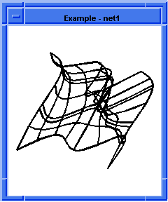
Figure 1. sheet:net-wires
; Additional Example
; Clear the previous part
(part:clear)
;; #t
(define c0 (edge:circular (position 0 0 0) 20 0 180))
;; c0
(define c1 (edge:circular
(position 0 -40 0) 20 180 360))
;; c1
(define u0 (wire-body c0))
;; u0
(define u1 (wire-body c1))
;; u1
(define v0 (wire-body:points (list
(position 15 -60 0)
(position 15 20 0))))
;; v0
(define v1 (wire-body:points (list
(position 10 -60 10)
(position 10 20 10))))
;; v1
(define v2 (wire-body:points (list
(position -10 -60 10) (position -10 20 10))))
;; v2
(define v3 (wire-body:points (list
(position -15 -60 0) (position -15 20 0))))
;; v3
(wire-body:offset v2 "4+4*sin (x*.25)" #f))
;; vo2
(define t1 (transform:rotation
(position -10 -60 10 ) (gvector 0 1 0) 90))
(define vo2
;; t1
(define new-t (entity:transform vo2 t1))
;; new-t
(define ops (skin:options "align" #t "simplify" #f))
;; ops
(define net2 (sheet:net-wires
(list v0 v1 vo2 v3)
(list u0 u1)
ops 11.0))
;; net2
; OUTPUT Example - net2

Figure 2.
sheet:net-wires
|
[Top]
sheet:skin-wires
- Action
-
Creates a sheet body that interpolates a series of wires.
-
Filename
-
scm/scmext/skin/skin_scm.cpp
-
APIs
-
api_skin_wires
-
Syntax
-
(sheet:skin-wires body-list [path] [skin-options] [acis-opts])
-
Arg Types
-
-
Returns
-
body
Description
The given wires define the cross-sections to be interpolated by the resulting
sheet body. There must be at least two wire bodies. The wire bodies are assumed
to be simple, meaning only the first wire of each body is used for skinning.
The wires can be open or closed. The wires are copies, i.e., the originals
remain. The wires can share end points and do not have to be C1 continuous
tangent.
- Arguments
-
body-list
is a list of wire bodies.
-
The optional argument
path
surface at each of the skinning profiles.
path
defines a curve that is intersected with the plane of each profile. At each of
the resulting intersection points on the curve the tangent vector is calculated
and applied to the surface as a constraint at that profile.
-
skin-options
gives the different options for skinning. For a complete list of skinning
options, please refer to the skin:options documentation.
-
acis-opts, which contain versioning and
journaling parameters, must be the last argument, if stated.
; sheet:skin-wires
; Create a wire body 1 from a circular edge.
; Set v and u parameters.
(option:set "v_par" 5)
;; -1
(option:set "u_par" 5)
;; -1
(define wire-body1
(wire-body (edge:circular (position 0 0 40)
40 0 270)))
;; wire-body1
; Create a wire body 2 from a circular edge 2
(define wire-body2
(wire-body (edge:circular (position 0 0 0)
40 0 270)))
;; wire-body2
; Create a wire body 3 from a circular edge 3.
(define wire-body3
(wire-body (edge:circular (position 20 0 -10)
40 0 270)))
;; wire-body3
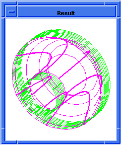
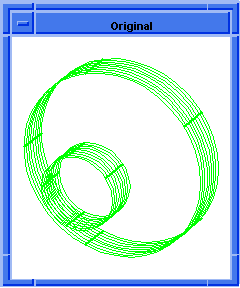
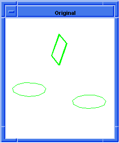
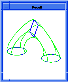
; OUTPUT Original
; Make a sheet body by skinning wires.
(define sheet1
(sheet:skin-wires (list wire-body1
wire-body2 wire-body3) "solid" #f))
;; sheet1
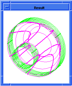
; OUTPUT Result
  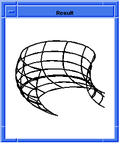
Figure. sheet:skin-wires
; Additional Example
; Create edge 1.
(part:clear)
;; #t
(define edge1 (edge:linear (position -20 -10 0)
(position 10 -10 0)))
;; edge1
; Create edge 2.
(define edge2 (edge:circular
(position 10 0 0) 10 270 360))
;; edge2
; Create edge 3.
(define edge3 (edge:linear
(position 20 0 0) (position 20 20 0)))
;; edge3
; Create edge 4.
(define edge4 (edge:linear
(position 20 20 0) (position -10 20 0)))
;; edge4
; Create edge 5.
(define edge5 (edge:circular
(position -10 10 0) 10 90 180))
;; edge5
; Create edge 6.
(define edge6 (edge:linear
(position -20 10 0) (position -20 -10 0)))
;; edge6
; Create a wire-body from the edges.
(define wirebody1 (wire-body (list
edge1 edge2 edge3
edge4 edge5 edge6)))
;; wirebody1
(define new-edge (edge:circular (position 0 0 10)
15 0 360))
;; new-edge
; OUTPUT Original
(define wirebody2 (wire-body (list
new-edge)))
;; wirebody2
(option:set "sil" #f)
;; #t
(option:set "u_par" 2)
;; 5
(option:set "v_par" 4)
;; 5
; Create a roll name state.
(roll:name-state "before")
;; "before"
; Skin a surface between these two wire bodies
; permitting twist and alignment
; without twist minimization.
(define skin1 (sheet:skin-wires
(list wirebody1 wirebody2) #f #f #t #f))
;; skin1
; OUTPUT Surface with twist
; Roll back before the skinning.
(roll "before")
;; 1
(view:refresh)
;; #[view 239847912]
; With twist minimization
(define skin1 (sheet:skin-wires
(list wirebody1 wirebody2) #f #t #t #f))
;; skin1
; OUTPUT Surface without twist
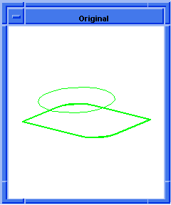  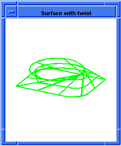
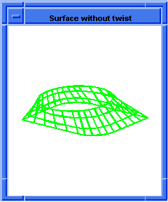
Figure. sheet:skin-wires
without and with Twist Minimization
|
[Top]
sheet:skin-wires-branch
- Action
-
Creates a sheet body that interpolates multiple series of two or more wires.
-
Filename
-
scm/scmext/skin/skin_scm.cpp
-
APIs
-
api_skin_wires
-
Syntax
-
(sheet:skin-wires-branch trunk-list branch-list
[skin-options] [normal-type] [ao]) -
Arg Types
-
-
Returns
-
body
Description
The given wires define the cross-sections to be interpolated by the resulting
sheet body. Unlike regular skinning, however; multiple body lists can be given.
Unlike regular skinning, the order of the wire-bodies in the lists are
important. The branches attach to the last body in the trunk. In
addition, the first bodies in the branch list are the ends in which they attach
to the trunk.
- Arguments
-
trunk-list
is a list of wire bodies that are arranged in the form of a trunk.
-
branch-list
is a list of wire bodies that are arranged in the form of a branch.
-
normal-type
has four values, "first_normal", "last_normal", "ends_normal" and "all_normal".
These values specify which profiles the normal constraint should be applied to.
In the case of "first_normal" the constraint is only applied to the first
profile. Other values, follow similarly.
-
skin-options
gives the different options for skinning. For a complete list of skinning
options, please refer to the skin:options documentation.
-
The
acis-opts, which contain versioning and
journaling parameters, must be the last argument, if stated.
- Limitations
-
A minimum of one wire branch is required.
; sheet:skin-wires-branch
; Create four wire bodies to illustrate command.
(define wire1 (wire-body (list (edge:circular
(position 0 0 70) 30 0 360))))
;; wire1
(define wire2 (wire-body (list (edge:circular
(position 0 0 0) 30 0 360))))
;; wire2
(define wire3 (wire-body (list (edge:circular
(position -50 0 -100) 30 180 (+ 180 360)))))
;; wire3
(define wire4 (wire-body (list (edge:circular
(position 50 0 -100) 30 0 360))))
;; wire4
; Create the branched body.
(define zoom (zoom-all))
;; zoom
(define refresh (refresh-all))
;; refresh
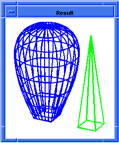
; OUTPUT Original
(define body (sheet:skin-wires-branch
(list wire1 wire2) (list wire3) (list wire4)))
;; body
; OUTPUT Result
(define blend (solid:blend-edges
(list-ref (entity:edges body) 6) 5))
;; blend
(define thicken (shell:sheet-thicken body -2))
;; thicken
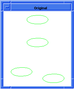  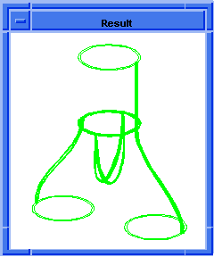
Figure.
sheet:skin-wires-branch
|
[Top]
sheet:skin-wires-draft
- Action
-
Creates a sheet body that interpolates a series of two or more wires leaving
the outer two wires at an angle specified by the draft angle.
-
Filename
-
scm/scmext/skin/skin_scm.cpp
-
APIs
-
api_skin_wires
-
Syntax
-
(sheet:skin-wires-draft body-list angle1 angle2
[[guides] | [start_normal] [end_normal]] [magnitude1] [magnitude2]
[skin-options] [acis-opts]) -
Arg Types
-
-
Returns
-
body
Description
The given wires define the cross-sections to be interpolated by the resulting
sheet body. There must be at least two wire bodies. The wire bodies are assumed
to be simple and well behaved. The wires can be open or closed. The wires are
copies, i.e., the originals remain. The wires can share end points and do not
have to be C1 continuous tangent. angle1 and angle2 define the
direction in which the created surfaces leave the first and last wires. More
specifically, the take-off direction (or take-off vectors), are generated by
the angle (draft) off the wire plane. If the wire profiles are not planar, the
approximate wire plane is used.
The optional arguments
magnitude1
and
magnitude2
define the weight of the generated take-off vectors.
- Arguments
-
body-list
is a list of wire bodies.
-
angle1
defines the direction in which the created surface leaves the first wire.
-
angle2
defines the direction in which the created surface leaves the last wire.
-
guide
is an additional surface constraint. The scheme commands almost always take a
list of guides. The input parameter guide is essentially an
EDGE.
-
skin-options
gives the different options for skinning. For a complete list of skinning
options, please refer to the skin:options documentation.
-
magnitude1
defines the weight of the generated take-off vector.
-
magnitude2
defines the weight of the generated take-off vector.
-
acis-opt, which contain versioning and
journaling parameters, must be the last argument, if stated.
- Limitations
-
A minimum of two wire bodies is required.
; sheet:skin-wires-draft
; Create two wire bodies to illustrate command.
(define wire_0 (wire-body (list (edge:linear
(position 0 0 0) (position 50 0 0))
(edge:linear (position 50 0 0)
(position 50 50 0)) (edge:linear
(position 50 50 0) (position 0 50 0))
(edge:linear (position 0 50 0)
(position 0 0 0)))))
;; wire_0
(define wire_3 (wire-body (list (edge:linear
(position 0 0 100) (position 50 0 100))
(edge:linear (position 50 0 100)
(position 50 50 100)) (edge:linear
(position 50 50 100) (position 0 50 100))
(edge:linear (position 0 50 100)
(position 0 0 100)))))
;; wire_3
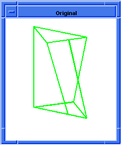
; OUTPUT Original
; Create the sheet body and interpolate wires at
; specified angle.
(define body (sheet:skin-wires-draft
(list wire_0 wire_3) 45 45 100 100))
;; body
; OUTPUT Result
; Example using guide curves
(part:clear)
;; #t
(view:dl)
;; #[view 28704984]
(wcs (position 0 0 0) (gvector 1 0 0)
(gvector 0 1 0))
;; #[entity 52 1]
(define wire_0 (wire-body (list (edge:circular
(position 0 0 0) 30))))
;; wire_0
(define wire_1 (wire-body (list (edge:circular
(position 0 0 50) 50))))
;; wire_1
(define guide1 (edge:spline (list (position 0 30 0)
(position 0 60 25) (position 0 50 50))
(gvector 0 1 1) (gvector 0 -1 1)))
;; guide1
(entity:set-color (list guide1) 1)
;; ()
(define body (sheet:skin-wires-draft
(list wire_0 wire_1) 45 45 (list guide1)))
;; body
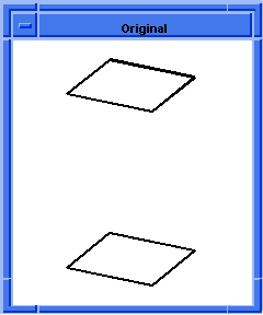  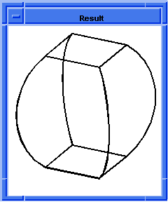
Figure. sheet:skin-wires-draft
|
[Top]
sheet:skin-wires-guides
- Action
-
Creates a sheet body that interpolates a series of wires with a guide curve.
-
Filename
-
scm/scmext/skin/skin_scm.cpp
-
APIs
-
api_skin_wires
-
Syntax
-
(sheet:skin-wires-guides body-list guides [skin-options] [acis-opts])
-
Arg Types
-
-
Returns
-
body
Description
The given wires define the cross-sections to be interpolated by the resulting
sheet body. The wire bodies are assumed to be simple and well-behaved. The
wires can be open or closed. The wires are copies, i.e., the originals remain.
The wires can share end points and do not have to be C1 continuous/tangent.
- Arguments
-
body-list
is a list of wire bodies.
-
guides
are defined to be the curves for which the skinning surface directly follows
(in the skinning direction). The guides must intersect each wire profile within
SPAresabs
and must start and end on the first and last profile exactly. Any number of
guides can be added and they may fall directly on vertices or not. Guides must
be C1 continuous and well behaved. (no - looping!).
-
skin-options
define the various options available for skinning. For a complete list of
skinning options, please refer to the skin:options
documentation.
-
acis-opts, which contain versioning and
journaling parameters, must be the last argument, if stated.
; sheet:skin-wires-guides
; Build the wires.
(define wire-1 (wire-body
(list (edge:circular (position 0 0 0) 5 0 360))))
;; wire-1
(define wire-2 (wire-body
(edge:circular (position 0 0 70) 5 0 360)))
;; wire-2
(define myWires (list wire-1 wire-2))
;; myWires
; Build the guides.
(define guide1
(edge:linear (position 5 0 0) (position 5 0 70)))
;; guide1
(define guide2
(edge:spline (list (position 0 5 0)
(position 0 5 8) (position 0 6 16)
(position 0 3 24) (position 0 6 32)
(position 0 3 40) (position 0 6 48)
(position 0 3 54) (position 0 9 62)
(position 0 5 70))))
;; guide2
(define guide3 (edge:linear
(position 0 -5 0) (position 0 -5 70)))
;; guide3
(define guide4 (edge:linear
(position -5 0 0) (position -5 0 70)))
;; guide4
(define myGuides (list guide1 guide2 guide3 guide4))
;; myGuides
(define ops (skin:options "arc_length" #f "no_twist"
#t "align" #t "simplify" #f "closed" #f
"solid" #t))
;; ops
; Make the body.
(define myBody
(sheet:skin-wires-guides
myWires myGuides #f #t #t #f #f #t))
;; myBody
; Use Skin_Options class.
(define opts (skin:options "solid" #f))
;; opts
(define myBody
(sheet:skin-wires-guides myWires myGuides opts))
;; myBody
; Zoom on picture.
(define zoom (zoom-all))
;; zoom
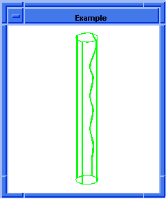
Figure. sheet:skin-wires-guide
|
[Top]
sheet:skin-wires-normal
- Action
-
Creates a sheet body that interpolates a series of wires with take off vectors
normal to the plane of the wire body.
-
Filename
-
scm/scmext/skin/skin_scm.cpp
-
APIs
-
api_skin_wires
-
Syntax
-
(sheet:skin-wires-normal body-list normal-type [skin-options] [acis-opts])
-
Arg Types
-
-
Returns
-
body
Description
The given wires define the cross-sections to be interpolated by the resulting
sheet body with the additional constraint of the surface take-off vectors
leaving normal to the plane of each of the wire bodies. There must be at least
two wire bodies. The wire bodies are assumed to be simple, meaning only the
first wire of each body is used for skinning. The wires can be open or closed.
The wires are copies, i.e., the originals remain. The wires can share end
points and do not have to be C1 continuous tangent.
- Arguments
-
body-list
is a list of wire bodies.
-
normal-type
has four values, "first_normal", "last_normal", "ends_normal" and "all_normal".
These values specify which profiles the normal constraint should be applied to.
In the case of "first_normal" the constraint is only applied to the first
profile. Other values, follow similarly.
-
skin-options
gives the description of all the options available for skinning. For a complete
list of skinning options, please refer to the skin:options
documentation.
-
The
acis-opts, which contain versioning and
journaling parameters, must be the last argument, if stated.
; sheet:skin-wires-normal
; Create an ISO view
(iso)
;; #[view 6161334]
; Create wire bodies
(define wire1 (wire-body (list
(edge:circular (position 0 0 0) 10 180 270)
(edge:linear (position 0 -10 0)
(position 100 -10 0))
(edge:circular (position 100 0 0) 10 270 360)
(edge:linear (position 110 0 0)
(position 110 25 0))
(edge:circular (position 100 25 0) 10 0 90)
(edge:linear (position 100 35 0)
(position 0 35 0))
(edge:circular (position 0 25 0) 10 90 180)
(edge:linear (position -10 25 0 )
(position -10 0 0)))))
;; wire1
(define wire2 (wire-body (list
(edge:circular (position 40 5 30) 10 180 270)
(edge:linear (position 40 -5 30)
(position 60 -5 30))
(edge:circular (position 60 5 30) 10 270 360)
(edge:linear (position 70 5 30)
(position 70 20 30))
(edge:circular (position 60 20 30) 10 0 90)
(edge:linear (position 60 30 30)
(position 40 30 30))
(edge:circular (position 40 20 30) 10 90 180)
(edge:linear (position 30 20 30 )
(position 30 5 30)))))
;; wire2
(define my_wcs1 (wcs (position 0 0 0) (gvector 1 0 0)
(gvector 0 0 1)))
;; my_wcs1
(wcs:set-active my_wcs1)
;; ()
(define wire3 (wire-body (list
(edge:circular (position 50 70 60) 20 0 360))))
;; wire3
(wcs:set-active #f)
;; ()
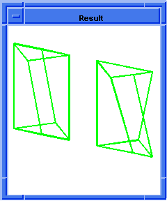
; OUTPUT Original
; Skin the wires
(define body (sheet:skin-wires-normal
(list wire1 wire2 wire3)
"all_normal" "solid" #f))
;; body
; Shell the body
(define thicken (shell:sheet-thicken body -2))
;; thicken
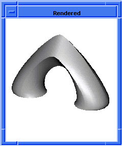
(render)
;; ()
; OUTPUT Result
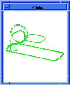  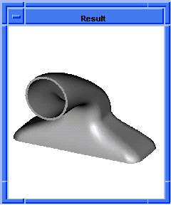
Figure.
sheet:skin-wires-normal
|
[Top]
sheet:skin-wires-vectors
- Action
-
Creates a sheet body that interpolates a series of wires with take off vectors
as constraints.
-
Filename
-
scm/scmext/skin/skin_scm.cpp
-
APIs
-
api_skin_wires
-
Syntax
-
(sheet:skin-wires-vectors body-list
SPAvector-list
[magnitude-list] | [guide-list] [skin-options] [acis-opts]) -
Arg Types
-
-
Returns
-
body
Description
The wires provided in the
body-list
argument, define the cross-sections to be interpolated by the resulting sheet
body. There must be at least two wire bodies. The wire bodies are assumed to be
simple, meaning only the first wire of each body is used for skinning. The
wires can be open or closed. The wires are copies, i.e., the originals remain.
The wires can share end points and do not have to be C1 continuous tangent.
- Arguments
-
body-list
is a list of wire bodies.
-
vector-list
is a list of vectors.
-
magnitude-list is a list of
magnitudes. Skinning with vectors accepts as additional constraints a list of
vectors and, optionally, a list of magnitudes to control the take-off
directions with which the skin surface leaves the profiles. The number of
supplied vectors has to equal the number of profiles if the closed option is
set to FALSE. If the closed option is set to TRUE one more vector can be given.
It will be used on the copy that is made of the first profile to create a
closed body. If no additional vector is provided the first vector will be used
also on the first profiles copy. In a similarly way, magnitudes can be
provided. A profile will be interpolated without constraint if the vector
supplied for it is the zero vector.
-
guide-list
is a list of guides.
-
skin-options
gives different options available for skinning. For a complete list of skinning
options, please refer to the skin:options documentation.
-
The
acis-opts, which contain versioning and
journaling parameters, must be the last argument, if stated.
[Top]
skin:options
- Action
-
Sets the options in the data structure to be used by skinning APIs.
-
Filename
-
scm/scmext/skin/skin_scm.cpp
-
APIs
-
None
-
Syntax
-
(skin:options {name-of-option value}
[skin-options]) -
Arg Types
-
-
Returns
-
skin_options
Description
Sets the skin_options scheme object that are used by the skinning and
lofting scheme extensions.
- Arguments
-
name-of-option
gives the name of the skin option.
-
value
is the value of the skin-option. Different name-of-option and its
default value are:
align (boolean): This option is used to align the direction of the
cross section curves such that the normal of the first profile points towards
the second profile. All other profiles are aligned to follow the first and
second. If the sections are not oriented in the same direction, the align
option should be used to avoid producing a twisted, self intersecting body. The
default value is #t.
allow_same_uv (boolean): This option allows surfaces with the same u
and v direction to be created. If the option is set to #t and a surface
with the same u & v direction is created, a warning will be
thrown. If set to #f, an error will be thrown.
Note: If this option is set to #t and a surface with the same u &
v direction is created, later modeling problems may appear.
arc_length and arc_length_u (boolean): The arc_length
option is used to choose arc length or isoparametric parameterization of the
skinning surface. For basic skinning and lofting in isoparametric
parameterization, the surface parameter in the v direction follows the
cross section curves. For arc length parameterization, the surface parameter
follows lines of constant length. The default is isoparametric
parameterization. In the case of skinning with guide curves with arc length
parameterization - the guide curve is arc length parameterized however the
surface is still isoparametric. The arc_length_u option
reparameterizes curves of the skinning or lofting profiles to arc length. The
default value is #f for both options.
closed (boolean): This option may be used when the user needs to
construct a solid body closed in v (i.e., a torus). A solid body will be
constructed only when all the wires supplied are closed. At least three
profiles must be provided to create a closed body. The default value is #f.
estimate_loft_tanfacs (boolean): When this option is on, the weight
factor for the tangency conditions of the loft will be determined such that it
minimizes the average radius of curvature of the lofting surfaces. The
resulting bodies should support shelling to greater thickness and also blending
of their edges to larger blend radii. The default value is #f.
gap_type (string): Specify the type of gap that will be placed between
the new faces. The type can be "extended" (extending the surfaces and
intersecting), "rounded" (tangent surface to both lateral faces) or "chamfered"
(a linear fill between both lateral faces). The default value is "extended".
guidePreference (string): This is an enumerated type with two possible
values, "constrain_to_guide" and "constrain_to_tangent". This
option is used to specify how an over constrained guide is resolved. If the
type "constrain_to_guide" is set, then the resulting lofting surface
will always stay with the defining guide curve. If the "constrain_to_tangent"
is specified, then the lofting surface will always follow the tangent
constraint. Default is "constrain_to_guide".
match_vertices (boolean): This option suppresses the
vertex-matching-algorithm which ensures that all profiles consist of the same
number of coedges. A heuristic approach is used to determine which vertex pairs
are good matches. Profile coedges are then split where additional vertices are
needed. This option is forced to #t if the coedge numbers of the profiles are
not equal. Its default value is #t.
merge_wirecoedges (boolean): When this option is set to #t, the G1
vertices of the skinning and lofting wire profiles are removed by merging
adjacent coedges/edges. This improves operations such as blending and shelling
as it reduces the coedge/edge count and the number of surfaces, and eliminates
near tangent edges. The default value is #t.
no_twist (boolean): This option may be used to minimize the twist of
the surface produced. Twist minimization aligns closed curves such that the
start of the second curve is aligned to the start of the first curve. Even if a
body's shape is unaffected by twisting, a surface with a twist could produce
unexpected results when faceting and rendering. The default value is #t.
no_new_twist_vertices (boolean): The algorithm that minimizes the
surface twist may add vertices to some of the profiles if none of the existing
vertices match well. This option allows the user to force the algorithm to
choose matching vertices from the existing vertices.
When the no_twist option is set to true, vertices can sometimes be introduced to
allow the skinning algorithm to reduce the energy of the skinned surface.
If topology must be maintained, setting the option no_new_twist_vertices
to true prevents such vertices from being created. This allows twist to be
minimized to the extent possible without creating new topology. Note that if
maintaining the exact input topology is not necessary, in some cases no_twist
may be able to mostly reduce twist if introduction of new vertices on the input
profiles is allowed. The default value is #f.
periodic (boolean): This option allows the construction of loft bodies
that are periodic in v, i.e., bodies that close back on themselves
smoothly (continuously) at the start and end profiles. This option is activated
in the skinning APIs by giving the closed option a value of 2. In Scheme, this
is achieved by setting the periodic flag to #t. As for the closed option, at
least three profiles must be supplied to create a periodic loft body. The
default is #f.
perpendicular (boolean): The take-off vector is a tangent vector going
out of the starting edge or surface and into the skinned or lofted surface. The
perpendicular option (for lofting only) is used to specify the
direction of the take-off vector, perpendicular to the coedge or in the loft
direction. (This removes any restriction that the take-off vector for the loft
has to be determined by the cross-product of the coedge tangent vector and the
surface normal times the tangent factor.) The default value is #f.
postprocess_stitch : This option stitches the resulting lofting body
to the original bodies from which its coedge definition came. This option only
works with
api_loft_coedges (lofting) and not with any skinning operation
(api_skin_wires).
It is identical in nature to the stitching operation performed in
api_loft_faces. The default is #t.
self_int_test (integer): This option checks for a self intersecting
skin surfaces. Commonly self-intersecting skin surfaces can be made based on
poor tangent factor magnitudes, poor profiles, or an incorrect usage of the perpendicular
option. If set to 0 the check will not be made and a body will be built however
later modeling problems may appear. If 2 is specified, the check will be
performed but it will notify with a warning. The default value is 1.
simplify (boolean): This option simplifies the surface to a conical
surface, if applicable. If all of the cross sections lie on a conical surface
(plane, cylinder, cone, sphere, or torus), the conical surface is created
instead. The
SPAresabs variable is used to determine whether or not the
cross section lies on a conical surface. The default value is #t.
smooth_g0_vertices (real): This option smooths wires during the skin operation. This
option attempts to convert "g0" connected vertices into "g1" connected vertices. The real value
associated with this option specifies the maximum smooth angle between two tangent vectors from
two connected curves at a "g0" vertex. Specify the angle in degrees when used in a scheme command,
or in radians in a C++ interface. If the angle value is less than or equal to zero, the option
is not applied.
Note: This option works better when merge_wirecoedges is enabled. When these options
are combined, the resulting skin body is smoother and has fewer short edges.
Therefore, this combination is more suitable for down stream operations such as boolean, blend,
offset, and shelling.
Furthermore, the option changes under line curve geometry; use with caution. The angle value should
normally be very small, less than 0.5 degrees. If you must apply the option to procedural curves,
use the scheme command entity:simplify-face-edge to convert them into b-spline curves
before using the smooth option. If a "g0" vertex is connected with an analytic curve and a
b-spline curve, the vertex can be smoothed with the smooth option; this is due to modifying the
b-spline curve alone to make the vertex into a "g1" connection.
solid (boolean): This option may be used when a solid loft must be
constructed but a closed body is not desired. When a closed body is not
desired, the end wires are capped with planar faces. The default is #t. This
option is forced to #f when skinning or lofting from faces or if the
postprocess stitch value is #t.
virtualGuides (boolean): This option may be used in order to have the
user-defined guides affect the body in a global nature. The default value is
#f.
skin-options
is a
skin_options
Scheme object. If placed at the end of the list, it will modify the list of
options selected in this Scheme object.
- Limitations
-
The perpendicular take-off vectors from the defining coedge cannot
intersect.
- The smooth_go_vertices option applies only to b-spline curves;
it does not apply to procedural or a analytic curves.
[Top]
© 1989-2007 Spatial Corp., a Dassault Systèmes company. All rights reserved.
![]()
