Standalone Deformable Modeling
The Standalone Deformable Modeling Component (SDM), provides a common deformable modeling kernel for both the standalone version and the ACIS version of deformable modeling.
Shape and shape features within larger shapes may be modified without changing the larger shape beyond a local bound by using local deformations. For example, after completing the design shape of a car door, a designer may want to insert a localized relief to make room for a flush door handle without changing the line of the car body. The shape of the relief feature is a local deformation to the car door.
Deformable modeling uses a simulation of an elastic curve or surface that mimics real-world behavior to change the shape being designed. Users may make small deformations from an existing shape or very large deformations to create an entirely new shape. The phrase "deformable model" refers specifically to a deformable curve or surface.
Deformable modeling uses an energy-based optimization strategy which minimizes the energy stored due to bending and stretching, so the shape that a deformable curve adopts is the one shape out of all possible shapes that minimizes the internal energy of the curve. This algorithm automatically produces very fair shapes similar to those seen in the billowing of a sail or the clean line of a bending beam.
Deformable modeling is a more powerful alternative to control point manipulation and skinning. Control point manipulation can change a shape interactively, but not while enforcing constraints. Skinning can build surfaces that satisfy several constraints but do not allow the shapes to be modified. With deformable modeling, users can interactively modify shapes while simultaneously satisfying a very rich set of constraints.
The deformable modeling algorithm is an operator and not a representation. It does not require any particular curve or surface representation. Editing for B-spline and NURB curves and surfaces is supported.
- Deformable Modeling Overview
- How to Use Deformable Modeling
- Deformable Models
- Behaviors
- Tags and Tag Objects
- Engineering Issues
- Limitations
Deformable Modeling Overview
Deformable modeling is a surfacing tool that allows you to easily modify all or part of curves and surfaces. It is useful for feature creation, feature modification, and surface adjustment. Since it uses a physics-based "rubber sheet" model, the modeling process is close to real-life processes, thus easy to use. And since it does not require control point manipulation, the computing cost is relatively low.
Feature creation allows you to make a bump, cover, or dome on a surface. For example, applying a distributed pressure to a square patch creates a raised area on the surface (see the Scheme extension ds:add-dist-press for details).
Feature modification includes the whole range of deformations.
Surface adjustment includes imposing continuity. For example, any deformable surface or curve can contain any number of child patches. A child patch may attach to its parent with either C0 (position only) or C1 (position and tangent) continuity. C0 patches allow a curve with corners to be defined, and C1 patches make smooth composite curves.
The physics-based interface makes it easy to think of deforming a model in terms of actual physical objects and behaviors. The material properties control how much the model resists bending and stretching. You can use the default-shape feature to deform shapes very far from their original shape by breaking one large deformation into a set of smaller deformations interspersed with default shape captures. Or, you can give a model a "preferred shape" to constrain its deformation. Constraints are used to limit and control deformations. Loads are used to pull or push.
Deformable modeling controls many degrees of freedom (control points) with only a few parameters, such as target locations and load gains. This greatly reduces computation time and simplifies coding.
How to Use Deformable Modeling
A sequence for a modeling session typically consists of the following steps:
-
Select a face or edge to be modified, or construct a shape model of a curve or
surface.
-
Construct a deformable model for the shape model.
-
Apply modeling options to affect the deformable shape (for example, add
features, loads, and constraints), and modify the parameters of the
constraints, loads, or deformation parameters.
-
Call
DM_solve to change the control point positions of the
deformable model.
-
Render the deformable model to see the change. You can loop back to steps 3 or
4 for interactive sculpting.
-
Repeatedly modify load and constraint parameter values, solve, and display.
- Once a desired shape is found, commit it to the face or edge. Or, if desired, restore the original face or edge shape.
You can further refine the modeling process by using the default shape feature, parameters, tag objects, and parametric positions.
To enable an interactive mode, the manipulation of the load and constraint parameters are tied to the mouse so that for each mouse move event there is a modify, compute, and render loop. SDM has been designed to minimize the update time of a basic modify, compute, and render loop, so it runs as an interactive animation.
Each load and constraint has a graphic icon: loads are shown in blue and constraints in red. During the editing of a sheet surface, the user may disable the face's boundary curve constraints so the boundaries of the sheet may be manipulated. Disabled constraints are shown in magenta.
SDM is designed to support two typical user scenarios for editing: the edit sheet and the edit solid face scenarios.
In the edit sheet scenario, the user starts by selecting a sheet face or a wire edge to edit. When a sheet face is selected, an SDM model of the sheet is made and it appears on the screen as a normal light shaded face. Each of the boundaries of the original sheet are automatically converted into curve constraints which are shown as red curves drawn within the surface. The user adds and manipulates loads and additional constraints until the surface is modified into a desired shape. The modified shape can be saved by committing it to the geometry kernel's model, at which time the original face's geometric description is backed up for roll back and then updated. Additionally, all face boundaries whose geometry have also been edited are similarly backed up and updated.
The edit a solid face scenario differs from the edit sheet scenario in that the user begins by selecting a face within a valid solid model. The face is automatically converted into a spline of a high enough degree and with enough control points so it can be reasonably edited. During the editing session, the user may not disable the boundary curve constraints. Preserving these constraints guarantees that the shape of the face continues to fit within the solid model after the sculpting has been completed. When the sculpted shape is committed back to the kernel geometry model, only the geometry of the face is updated, since the boundary curve shapes have been preserved.
When the function DM_solve is called, it uses an optimization procedure to compute the optimal control-point positions for a deformable model given the model's current set of loads, constraints, and deformation parameters. After generating a solution for the deformable model or its deformable mesh, this function recursively generates a solve solution for all of the model's siblings and offspring or all of the mesh offspring. So a single call to this function on the root of a hierarchy tree will update all of the hierarchy's shapes.
Deformable Models
A deformable model (sometimes abbreviated "dmod" in the code) refers to the geometry to be deformed. Deformable models can be splines, surfaces, or curves. When a solid body is deformed, it is the surface of the solid that is operated on.
Modeling Domains
Domains are parametrically defined sub-regions of a deformable model. Domains can be one or more points, curves, zones or areas, point-sets of discrete points, or links (as in a multi-surface mesh). Behaviors act upon a domain. You can think of it as drawing a point, curve, or area on rubber sheet, and then stretching or deforming the sheet only within those boundaries.
A location on a curve or surface is identified by a parametric position specified by uv coordinates (surfaces) or u coordinates (curves). All deformable model curves and surfaces are parameterized on the unit square. That is, the parameter values always vary from 0 to 1 with the value of 0.5 being the middle. Any scaling required to map the deformable model parameterization to that of the internal deformable model parameterization is made by the deformable modeling package for the user.
Surfaces
Surfaces can be stitched together to form multi-surface meshes (no multi-curve capability at this time). The individual surfaces within the mesh are connected to one another by link curve loads. Within the deformable modeling mesh, each surface is equivalent to a FACE and each link load is equivalent to an EDGE in a boundary representation model.
The figure below shows how two surfaces are combined into a single deformable modeling mesh by the existence of a link load (shown in red). Either C1 or C0 continuity between each surface patch can be enforced as the patches are deformed.

Figure. A Multi-surface Deformation Mesh
The basic strategy for building a multi-surface mesh in the SDM API is to make a deformable model for every surface in the mesh, and then to add a link constraint for every connection within the mesh. In pseudo code this sequence looks like the following.
| // for every surface in the mesh for(ii=0;ii<surface_count;ii++) { // define the surface's shape function pfunc_array[ii] = DM_make_bspline_surface( rtn_err, ...); // make the surface's deformable model surface_dmod[ii] = DM_make_dmod_surface( rtn_err, pfunc_array[ii], ...); } // end iterate every surface in the mesh // for every edge in the mesh for(ii=0;ii<edge_count;ii++) { // find the faces for the edges face1_index = USER_get_face_index_for_edge(edge[ii],1) ; face2_index = USER_get_face_index_for_edge(edge[ii],2) ; // build the domain curve description src1_C_pfunc = USER_make_pfunc_for_edge_on_face( edge[ii],face1_index) ; src2_C_pfunc = USER_make_pfunc_for_edge_on_face( edge[ii],face2_index) ; // build the link cstrn link_tag[ii] = DM_add_link_C0_load (rtn_err, tag_shift, surface_dmod[face1_index], surface_dmod[face2_index], domain_flag, src1_C_pfunc, src2_C_pfunc,...) ; } // end iterate every edge |
After the multi-surface mesh is constructed, a call to DM_solve computes the deformed shape for the entire multi-surface mesh.
Patches
A patch defines a local area of the surface where deformations are applied. A patch is itself a deformable model. A child patch can be applied to any deformable curve or surface. Once applied, the patch is also a deformable curve or surface with all associated capabilities.
Deformable model patches may be nested in a hierarchical tree in which the links in the tree represent containment and the nodes represent individual deformable models. Children in the tree are connected to their parents through a set of seam constraints that ensure that the child shape can connect to the parent shape with C0, C1, or C2 (curves only) continuity. The tree is represented in the DS_dmod structure as a set of three pointers: parent, child, and sibling. A child patch can own a child patch (grandchild).
Any deformable surface or curve can contain any number of child patches. Each child patch is attached to its parent through a seam, similar to a seam in sewing that joins two pieces of fabric. A seam is one or more curves that connect together to form a simple closed loop. The child patch connects to its parent patch along the seam with C0 (position) or C1 (position and tangent) continuity.
Deformations made to the child do not affect the shape of the parent. Deformations of the parent change the shape of the child so that the child continues to stay attached to the parent curve. The child's attachment to its parent is enforced by using the point constraint mechanism. A child patch is totally contained by its single parent, which prevents child patches from spanning across link constraints.
The shape of each child patch on a surface is a rectangle large enough to contain its seam. The child patch's shape outside the seam is trimmed away, allowing the boundary of the patch to form any shape. The final curve or surface shape is defined by the child patch for locations within the seam boundary. For locations outside the seam, the final curve or surface shape is defined by the parent.
On a curve, a patch is a second curve which is attached to its parents at its end points and is defined over a subset of the parents' domain space. The actual curve, as seen by the user, is really a composite curve, defined by the parent curve outside the patch region and defined by the child patch within the patch region. A child patch may attach to its parent with either C0 (position only) or C1 (position and tangent) continuity. C0 patches allow a curve with corners to be defined, and C1 patches make smooth composite curves.
Curves
The modeler moves control point positions based on inputs such as loads, constraints, and material properties. The following figure shows a sample curve defined by interpolating four constraint points (shown as magenta squares). The curve is deformed by moving one of the interior constraint points through a sequence of positions. The curve's control points are shown (as blue dots) for the first and last shape in the sequence. In this example, moving one constraint point drives the deformable modeling algorithm, which moves all the control points to continue interpolating all the constraint points and to keep the curve fair. Any number of point constraints can be added to a curve placed at any position on the curve.
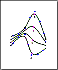
Figure. Deformable Curve
DS_zone Objects
A DS_zone object partitions a deformable model's shape into two regions, inside or outside the zone. Because the zone's boundaries may not align with the deformable model's elements boundaries, a zone partitions the elements of the affected shape to also include those elements crossing the zone's boundary.
To construct a DS_zone object, define the boundary shape within the domain space of the deformable modeling shape. A rectangular DS_zone object can be constructed using DM_build_square_zone, defining the minimum and maximum corner locations of the rectangle.
A constructed zone can return:
- a list of all elements which are completely in the zone
- a list of all the degrees of freedom (DOFs) that affect the shape of the in-elements
- the local list of degrees of freedom that affect the shape of the in-elements only
A degrees of freedom in the local list affects the shape of the zone's in-elements only. A degrees of freedom in the total list may also affect the shape of elements not completely within the zone.
Default Shape
The default shape is that which the modeler seeks in the absence of any constraints and loads. There are two options for setting the default shape:
- The current shape may be captured as the default shape.
- The default shape may be set to zero.
By default, the original resting shape is for the deformable model to be flat and of zero area (or length). A nonzero default shape is useful for designing a small, smooth deviation from the given input shape. At any time the current shape of the deformable model can be captured as the default shape with the function DM_set_default_shape.
A zero default shape is useful for constructing elegant surfaces stretched between curve constraints, much like soap films stretched across coat hangers.
A deformable model will always have a default shape set immediately after start-up. If the model is restored from attributes with a stored default shape set, then that will be used; otherwise Set_default_shape(1) will be called automatically. The intent of this behavior is that calling Solve_dmod immediately after reading in a model is a null operation. If this behavior is not desired, then Set_default_shape(0) can be explicitly called to erase the default shape.
The default shape feature may be used to deform shapes very far from their original shape by breaking one large deformation into a set of smaller deformations interspersed with default shape captures. In such a situation, the deformed shape is a function of its default shape and the current set of applied loads. Alternatively, when attempting to create a smooth surface connecting a framework of curve constraints, the default shape can be removed or "zeroed." The shape of the deformed surface then becomes only a function of the curve constraints and the current set of applied loads.
The following figure illustrates the default shape feature for deformable curves. The initial curve a is a simple figure eight. This shape is captured as the curve's default shape. Two end constraint points are added to the curve. Curve shapes b and c are made by pulling the upper point constraint towards the lower left corner. The default shape feature ensures that the curve loops twice between the two endpoints no matter where those endpoints move in space.
The shape that a deformable curve adopts is the one shape out of all possible shapes that minimizes the internal energy of the curve.
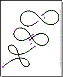
Figure. Default Shape
Behaviors
Behaviors are things you can do to a deformable model. The three main types of behaviors are constraints, loads, and material properties. Constraints control the exact shape of a deformable model at locations where such control is required. Loads pull or push deformable models approximately to a location. Material properties define a model's resistance to bending, stretching, and other deviations from the default shape.
A geometry spring-load is specified by position, tangent, curvature, and pressure load.
Behaviors are applied to a deformable model at specific domains, as for example applying a point constraint to a point, a curve spring load to a section of a curve, or an area pressure to a child patch on a surface.
Applying Behaviors to Models
Behaviors are associated with domains by load and constraint objects, which associate a domain with one or more specific behaviors that can be toggled on or off.
A link spring load (load) has a parameter-curve domain, and can have position, tangent, and curvature spring load behaviors applied.
Area pressure (load) has a rectangular area domain, and accepts pressure load behavior.
A point constraint on a surface (curves have different behaviors) has a single parameter-point domain. An area constraint can lie inside or outside a rectangular area domain, and accepts position geometry constraint behavior.
Geometry behaviors (spring loads and constraints) will have targets. A target is the xyz location to which the behavior is pulling the surface. For every point in the domain, there is a corresponding target location "point" in the target. A position spring load on a curve domain (that is, spring curve load with position behavior on) will have an xyz curve as target. A tangent spring load on a curve domain (that is, spring curve load with tangent behavior on) will have a 1-parameter xyz vector-valued (vector output) function as target.
Loads
Loads can be applied to either a point, an area, or a curve domain. Multiple independent pressures can be applied to a deformable model. Basic load types are as follows:
-
Spring
- Curve spring
- Point spring
- Point spring set
-
Pressure
- Distributed pressure
- Point pressure
-
Attractor
- Point attractor
-
Vector
- Distributed vector load
Link Spring Loads
A link curve load acts between (links) a parameter curve line in the surface of the target and a three dimensional line, or between a parameter curve line in the surface of the target and an ellipse. It is a distributed spring which connects a set of points on the deformable model to a set of points in three dimensional space with
| amplitude = gain * (distance between the two points)**2 |
This force acts to keep the point in the surface near its associated three dimensional space point, which is helpful in forcing the shape of the overall surface.
Even though multiple behaviors can be associated with one curve load, it is strongly recommended that a different curve load be added for each behavior to be controlled. Each behavior will then have a separate tag which can be used to separately tune how closely the curve is pulled to position, tangency, or curvature targets.
Pressure Loads
A point pressure load is firmly fixed at one location of a deformable surface and applies a force that always acts normal to the surface. The force's gain or its location in the surface can be altered. Surfaces tend to bend in the direction of the point pressure when the pressure's gain is increased. Gain values may be positive or negative. Positive gains "puff" surface shapes, while negative gains "suck" them. Point pressures on deformable curves act in the curve's bi-normal direction.
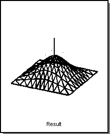
Figure. Point Pressure Gain
An area pressure is a normal force applied to a continuous subregion of a deformable model. Increasing the gain tends to make the surface bellow. The domain of the distributed pressure can be limited so that it only acts on a portion of a surface.
Figure. Area Pressure (Puff)
Vector Loads
A vector load is a constant vector force applied to the entire deformable shape. This load can be used to simulate a gravity-like effect. A user can modify the vector load by increasing its gain, or by changing the vector's direction. Objects subjected to a vector load tend to sag around their constraints.
Attractor Loads
An attractor load acts like an electrical point charge, either attracting (negative gains) or repulsing (positive gains) the deformable model shape with a 1/distance**power law. The distance is measured from the attractor's location to each point on the deformable model. The rate at which the force charge decreases is controlled by a parameter called power. Larger values of power increase the rate at which the force diminishes. Values of power greater than 2 make the load a very local load. With an attractor, a portion of a deformable model can be made to move away from or towards an attractor.
An attractor load can be modified by changing the power, the input position, or the gain.
Material Properties
The automatic behavior of a deformable model may be altered by changing the material properties. These variables include:
- alpha
- The deformable model's resistance to stretch.
- beta
- The deformable model's resistance to bending.
- gamma
- The deformable model's resistance to the rate of change in bending.
- delta
- The deformable model's resistance to deviations from the default shape.
The alpha variable directly weights the amount of energy due to stretching. In a curve, the alpha weighted term is identical to arc length. Stretch is a local measure of the overall length of a curve and alpha weights the resistance to it. A curve with a large alpha value is said to be stiff. Deformable models with large alpha values act like soap bubbles seeking to always minimize their area. This results in flatter looking surfaces that allow regions of rapid bending.
Deformable models with large beta values act like elastic beams attempting to distribute regions of bending over large areas and generate very fair shapes. Larger and larger curvatures continue to increase the energy due to bending. The bending energy weighted by beta can only be zero when the curve is flat. So, although beta does not actually weight a curvature measure, it does act to resist curve bending.
The gamma term is another smoothing term that works well for deformable curves. Resisting the rate of change of bending helps to resist the rate of twist in a curve, which helps to increase the fairness of a deformable curve. The gamma does not work well with deformable surfaces.
Delta is the gain of a distributed spring force that connects the deformed shape to the default shape. Deformable models with nonzero delta values resist the effects of spring loads and point constraints. It is not necessary for enforcing the default shape behavior of the deformable model. Even with a zero value for delta, the deformable model continues to seek out the default shape when no loads or constraints are applied.
- The actual deformable model's behavior is a function of the ratios of these parameters. A good starting set of surface parameters are
-
alpha = 1
- beta = 5
- gamma = 0
- delta = 0
- beta = 5
Constraints
The three types of constraints are point, curve, and link. Constraints are restrictions on shape that a deformable model must satisfy while it is being modified. Constraints can be applied to individual points within the surface or may be applied to curves within the surface, or may be applied to zones within a surface. A constraint can restrict position, tangent, normal, and curvature. See the function descriptions ( DM_add_pt_cstrn, DM_add_link_cstrn, and DM_add_crv_cstrn) for details.
The following constraints are supported:
Surfaces
- Point position constraint
- Constrains any point on a surface to interpolate any point in space.
- Point tangency
- Constrains the tangency of any point on a surface.
- Point curvature
- Constrains the curvature of any point on a surface.
- Point normal constraint
- Constrains the direction of the surface normal at any point on a surface to point in any direction.
- Curve position constraint
- Constrains any curve within the surface to interpolate a curve in space.
- Curve tangent constraint
- Constrains the surface tangent across any curve in the surface to point in a given direction. The curve tangent constraint is used to connect a child patch to its parent patch with C1 continuity. A combination of the curve position and curve tangent constraints fixes the surface normal along the length of the curve constraint.
- Curve curvature constraint
- Constrains the surface curvature across any curve in the surface.
Curves
- Point position constraint
- Constrains any point on a curve to interpolate any point in space.
- Point tangent constraint
- Constrains the curve tangent direction at any point on a curve to point in any direction.
- Point curvature constraint
- Constrains the curvature magnitude and curvature plane at any point on a curve.
With deformable modeling, users can add any combination of the above constraints to a deformable model at run time while applying any combination of loads.
Point Constraint
A point constraint can specify the geometry properties (position, tangent, normal, and curvature) of a point on a deformable model shape. The basic pattern for using a point constraint is:
- Create and apply the constraint to a deformable model using DM_add_pt_cstrn.
- Select which geometry properties are being constrained, using DM_set_cstrn_behavior.
- For tracking pt_cstrns, modify the geometry property values by moving the point constraint display points with DM_set_pt_xyz.
- Call solve to see how the constraint modifications changed the deformable model shape, DM_solve.
Optionally, change the point constraint's domain position and domain directions (directions for directional derivatives on surfaces) with DM_set_pt_uv or DM_set_cstrn_pttan_uv_dir.
Optionally, modify the constraint image_pt locations to optimize viewing and/or interactions, with DM_set_tan_display_gain or DM_set_comb_graphics.
Curve Constraint
A curve constraint may act to constrain any combination of the shape's position, tangent, and curvature along the length of the curve constraint determined by the behavior bit array value specified in the arguments for DM_add_crv_cstrn.
Link Constraint
A link constraint connects two root siblings to make two deformable models act as one. The constraint is described by the shapes of two curves embedded within the deformable models that they constrain. It also specifies if their shape is to be C0, C1, C2, or discontinuous across this link constraint.
Tags and Tag Objects
A tag is an ID code (an integer) for a tag object. Deformable models, constraint objects and load objects are all tag objects. A tag object is acted on through the interface by specifying its tag as an input argument. Behaviors within a constraint object or load object tend to be identified by a pt_index argument in interface calls.
For example, in most of the Scheme extensions for deformable modeling, the target argument, which specifies the deformable model, is an integer tag. The target can be specified to be the active deformable model, the root deformable model, the active deformable model and offspring, or the root deformable model and offspring. If none of those are specified, the target is the deformable model whose tag identifier equals target. The extension will return an integer tag for the load or constraint it applies.
It is the calling application's responsibility to guarantee that assigned tag numbers are unique throughout the entire deformable modeling hierarchy. If you always use DM_assign_next_tag to select the tag value for each tag object entered into a deformable model tag hierarchy, then every tag object in the hierarchy will have a unique value.
Tags maintain their unique identifier status. For example, when DM_add_link_cstrn forces two deformable models to deform as if they were one, all of the tag identifiers in the second model's deformable modeling hierarchy are shifted by the output amount, tag_shift, to guarantee their uniqueness in the combined deformable modeling hierarchy. If the two models are already siblings, tag_shift is set to 0, and all the tag numbers are not changed.
Engineering Issues
To avoid problems when using deformable modeling, the developer should be aware of these issues and address them in the early stages of development.
Memory Management
When constructing DS_zone objects to use as inputs for area constraints, the returned zone object is malloced and must be freed by the application at the appropriate time. However, once the zone is used to make an area constraint or some other kind of tag object, the SDM library will free this memory when asked to free the tag object.
journaling:
DM_journal_off
DM_journal_on
DM_journal_play
Comparing Loads and Constraints
Loads have tolerances; constraints do not.
Loads have two attributes that constraints do not: linearity and gain.
The difference between using the DM_add_link_C0_load function and DM_add_link_cstrn is in how the link constraint is enforced. The load function uses a spring load (which is equivalent to a penalty method) for enforcing the constraint, while the DM_add_link_cstrn call enforces the link constraint with lag range variables. The difference is that the penalty method will tend to be more tolerant, which can be an advantage if the constraint is being enforced too stiffly to bend properly with the lag range constraint approach.
Load Linearity and Gain
Loads have two attributes that constraints do not: linearity and gain.
Loads that are not linear must be solved with a -1 iteration flag. Constraints are always linear, so the -1 iteration flag is not needed. The nonlinearity in pressures and attractors comes from the dependence of the force, that is, energy equation right hand side, on the current shape of the deformable model.
Gain measures the strength or force of the load. For some loads, changing the gain changes both the left and right side of the energy equations, requiring a relatively expensive re-factorization. Constraints always change only the right side of the energy equations, requiring a relatively cheap solution. The load types are tabulated below by these two considerations.
In the limiting case of large gain, a spring behaves like a constraint. For both constraints and loads, adding or deleting requires a relatively expensive factorization, while tracking requires a relatively cheap solution.
Continuity and periodicity are two "hidden" constraints. If a spline has knots with only C0 continuity, when a deformable model is created, constraints will be inserted to force C1 continuity at these knots. These can be toggled using DM_set_interior_state. If a spline is periodic, when a deformable model is created, constraints will be inserted to force periodicity.
Table. Load Linearity
| Linear Loads | Nonlinear Loads |
| Spring | pressure |
| Vector | Attractor |
Table. Load Gains
| Gain change --> RHS changes
(cheap) |
Gain change --> LHS changes (expensive) |
| Pressure | Spring |
| Attractor | |
| Vector |
Limitations
There are a few limitations in this version of Deformable Modeling, as outlined below.
- No child multi-surface patches
- No multi-edge mesh
- No tracking curve constraints
- Exception handling across interfaces
- Sculpting non-pseudoplanar surfaces
- Surfaces with non-uniform parameterizations
In this release, material properties, loads, and constraints (other than link constraints) continue to be applied to individual deformable models. For example, if an application desires to apply a pressure over an entire multi-surface mesh, the application is obligated to apply a distributed pressure to each surface within the mesh.
No Child Multi-Surface Patch
Only root deformable models are allowed to form deformable modeling meshes. Child patches continue to be limited to being single deformable modeling patches. In addition, a child patch continues to be totally contained by its single parent. This limitation prevents child patches from spanning across link constraints.
No Multi-Edge Mesh
Multi-surface meshes are supported, but multi-edge meshes are not.
No Tracking Curve Constraints
Currently, the shape of the link constraints can not be specified by the application and all the surfaces can not deform to follow a changed curve shape. Tracking curve constraints are isoparametric only. There are no limits on curve load tracking.
Exception Handling Across Interfaces
Exception handling across interfaces is problematic, because different libraries may have different exception handling methods, such as C++ try/catch or C setjmp/longjmp. The Spatial_abs_hurler interface class provides a protocol for handling exceptions across interfaces. Interface routines taking a Spatial_abs_hurler agree to trap all exceptions, translate them to an integer code, and then call the Spatial_abs_hurler::rethrow_error method with the integer code.
Sculpting non-pseudoplanar surfaces
Deformable Modeling is a method for translating local inputs into smooth, global changes in the shape of a surface. It can be thought of in terms of pushing and pulling on a 2D rubber sheet (as opposed to a 3D rubber solid). Because of the 2D nature of the smoothing term in Deformable Modeling, it is best suited to working with "pseudoplanar" surface regions, that is regions of a surface for which the normal vectors all point roughly within 20-40 degrees of the same direction. The issue is that non-pseudoplanar surfaces (such as a torus or cylinder) can be associated with an enclosed volume; this is especially true if the surface is closed. Since the deformation energy models 2D sheets rather than 3D volumes, the enclosed volume does not behave in a physically intuitive manner when the corresponding surface is deformed. For example, imagine pulling radially outward at two opposing points on a cylindrical pant leg in an attempt to stretch the shape; the points which are being pulled move outward, but the "sides" of the cylinder away from the pulled points actually move inward, causing an unexpected shape. However, if the cylinder is clamped down roughly 30 degrees to either side of the pulled points, the deformation is limited to two pseudoplanar regions of the cylinder and the resulting shape is as expected.
For this reason, it is best not to use Deformable Modeling to form complex shapes from first principles. Instead, standard modeling techniques should be used to obtain a rough shape, which can then be adjusted using Deformable Modeling.
Surfaces with non-uniform parameterizations
The energy function which is minimized in Deformable Modeling depends on parametric (rather than geometric) derivatives of the surface. This causes surfaces with highly varying parametric velocities (that is, where the coordinate lines are much closer together in one region of the surface than another) to be stiffer in regions where the parametric velocity is low than in regions where it is high. For example, a cone will be stiffer near the apex, where the radial coordinate lines are close together, than at the base. This effect should only be significant for surfaces with a large variation in parametric velocities, usually due to a coordinate singularity as on a sphere or a cone.
[Top]
© 1989-2007 Spatial Corp., a Dassault Systèmes company. All rights reserved.