1 = active deformable model 2 = root deformable model
Otherwise, the
target
is the deformable model whose tag identifier equals target.
- Arguments
-
owner
is an ACIS face or edge on which the deformable model lives.
-
target
specifies which deformable model to use in a patch hierarchy.
-
zone-flag
indicates the fixed and complement area.
-
uv1 and uv2
specify the opposite corners of the square.
-
pick-event1 and pick-event2
add point constraint at the first intersection between a ray and the deformable
surface or curve.
; ds:add-area-cstrn
; ds:add-area-cstrn
; Use an area constraint to enable an isolated
;   deformation
; Build a test square spline face.
; (25x25 control points, x and y side length = 36)
(define dsmodel1 (ds:test-face 25 25 36 36 0))
;; dsmodel1
; Render the elemnts, loads, and constraints.
(ds:set-draw-state dsmodel1 2 (+ ds-draw-elems (+ ds-draw-cstrns ds-draw-loads)))
; Add an area constraint and a pressure load.
(define c1 (ds:add-area-cstrn dsmodel1 2 0 (par-pos 0.2 0.2) (par-pos 0.8 0.8)))
(define c2 (ds:add-dist-press dsmodel1 2 100000))
; solve for the new shape.
(ds:solve dsmodel1 2)
; The square shape, constrained along its edges
; rises in the middle where deformations are allowed
; Commit the deformable surface back to the model.
(ds:commit dsmodel1)
; Perform a zoom-all to see everything.
(zoom-all)
|
[Top]
ds:add-attractor
- Action
-
Adds an attractor load to a deformable model and returns the new attractors tag
identifier.
-
Filename
-
scm/scmext/ds/dsscm.cpp
-
APIs
-
api_dm_get_attrib_dm2acis
-
Syntax
-
(ds:add-attractor owner target=1 [xyz-position] [power=2]
gain=100) -
Arg Types
-
-
Returns
-
unspecified
- Description
-
Adds an attractor to the owners deformable model and returns the new loads tag
identifier.
owner
is the face or edge being deformed.
- The
target
argument specifies which deformable model to use in a patch hierarchy. Valid
values for
target
are:
-
1 = active deformable model
-
2 = root deformable model
-
-1 = active deformable model and offspring
-
-2 = root deformable model and offspring
Otherwise, the
target
is the deformable model whose tag identifier equals target.
An attractor acts like a concentrated charge either attracting (negative gains)
or repulsing (positive gains) the entire deformable model shape with a
1/distance**power law. The distance is measured from the attractors location to
each point on the deformable model.
The input argument
xyz-position
is optional. When given it is used to define the location of the attractor.
When omitted the location is taken as an offset from center of the deformable
model in the direction of surface normal at that point.
The input argument
power
is optional. When omitted it is set to 2. The power specifies how local the
effect is. Values of 0 and 1 are global and values of 2 and higher are more
local.
- Arguments
-
owner
is an ACIS face or edge on which the deformable model lives.
-
target
specifies which deformable model to use in a patch hierarchy.
-
xyz-position
is used to define the location of the attractor.
-
power
specifies how local the effect is.
-
gain
is a measure of how strongly the load pulls the deformable model to its target.
[Top]
ds:add-circ-cstrn
- Action
-
Adds and returns the tag identifier for a circular constraint curve to a
deformable model.
-
Filename
-
scm/scmext/ds/dsscm.cpp
-
APIs
-
api_dm_get_attrib_dm2acis
-
Syntax
-
(ds:add-circ-cstrn owner target=1 behavior uv-center
uv-a uv-b [element-count=8 integral-degree=10]) -
Arg Types
-
-
Returns
-
integer
- Description
-
Adds a circular curve constraint to the target deformable model of the
owner
and returns its
target
identifier. The curve constraints force the surface to interpolate exactly the
circular constraint during subsequent deformations.
- The
target
argument specifies which deformable model to use in a patch hierarchy. Valid
values for
target
are:
-
1 = active deformable model
-
2 = root deformable model
-
-1 = active deformable model and offspring
-
-2 = root deformable model and offspring
Otherwise, the target is the deformable model whose tag identifier equals
target.
- The parameter curve shape is specified by a point:
uv-center
and two vectors:
uv-a, and
uv-b. The curve is centered on point
uv-center
and its minimum and maximum radii are set by the vectors
uv-a
and
uv-b. The equation for the parameter
space curve is:
-
P-curve(s) =
uv-center
+ cos(s)uv-a
+ sin(s)uv-b
for 0 <= s <= 2*pi
The u and v values in
uv-center,
uv-a, and
uv-b
are scaled to range from 0.0 to 1.0.
The parameter space curve is divided into element-count elements for building
the constraint equations. More elements increase the cost of computation but
reduce the size of the error.
integral-degree
specifies the accuracy of numerical integration used within each element. (A
polynomial function of degree
integral-degree
will be integrated exactly.) Increasing the
integral-degree
increases the computation cost and reduces the error.
-
behavior
specifies whether the position and/or the tangent of the deformable model
across the curve is constrained along the length of the curve. The valid string
values for
behavior
are:
-
- "position" or "p"
-
- "tangent" or "t"
-
- "curvature" or "c"
-
- "pos_tan" or "pt"
-
- "pos_cur" or "pc"
-
- "tan_cur" or "tc"
-
- "pos_tan_cur" or "ptc"
-
For link constraints, one of three states for four different parameters must be
specified. The valid states are:
-
0 = off
-
f = fixed
-
l = linked
-
The four different parameters to set are:
-
- curve_1_position
-
- curve_1_tangent
-
- curve_2_position
-
- curve_2_tangent
Therefore, a total of 81 different behavior states are allowed for a link
constraint. These states can be specified by the string
pos_?_?_tan_?_?
where the question marks can be one of
off
or
o,
fixed
or
f, or
linked
or
l. As an example, the string
pos_linked_linked_tan_off_off
or
pll_too
sets the behavior to
DM_POS_LINKED
|
DM_POS_2_LINKED
|
DM_TAN_FREE
|
DM_TAN_2_FREE.
- Arguments
-
owner
ACIS face or edge on which the deformable model lives.
-
target
specifies which deformable model to use in a patch hierarchy.
-
behavior
whether the position and/or the tangent of the deformable model across
the curve is constrained along the length of the curve.
-
uv-center
is a center point.
-
uv-a
minimum radius.
-
uv-b
maximum radius.
-
element-count
elements for building the constraint equations.
-
integral-degree
specifies the accuracy of numerical integration used within each element. -
Limitations
-
Circular constraints may only be added to deformable surfaces. They are not
supported for deformable curves.
; ds:add-circ-cstrn
; Create a test face for this constraint.
; (6x6 control points, x and y side length = 36)
(define dsmodel1 (ds:test-face 6 6 36 36 0))
;; dsmodel1
; Dont display entity / ds test face exists.
(define erase (entity:erase dsmodel1))
;; erase
; Render the loads and constraints.
(ds:set-draw-state dsmodel1 1
(+ ds-draw-cstrns ds-draw-loads))
;; ()
; Add a circular constraint at the squares center
(ds:add-circ-cstrn dsmodel1 1 "position"
(par-pos 0.5 0.5) (par-pos 0 0.3)
(par-pos 0.3 0))
;; 7
; Toggle off the default crv-cstrns
(ds:toggle-cstrn dsmodel1 1)
;; 0
(ds:toggle-cstrn dsmodel1 2)
;; 0
(ds:toggle-cstrn dsmodel1 3)
;; 6
(ds:toggle-cstrn dsmodel1 4)
;; 6
; OUTPUT Original
; Add a pt-cstrn at the center and track it.
(define cc1 (ds:add-pt-cstrn dsmodel1 1
"position" (par-pos 0.5 0.5)))
;; cc1
(ds:set-pt-xyz dsmodel1 cc1 0
(position 20 10 0))
;; 8
; Compute a new deformable model position.
(ds:solve dsmodel1 1 1)
; *** Warning
; (dshusk/ds2acis:DS_LOW_DOF_CNT_WARNING)
; DS_warning - low dof count - Consider ds:split-d
;; ()
; dsmodel1 deforms to interpolate the point
; and the curve constraint.
; Commit the deformable surface back to the model.
(ds:commit dsmodel1)
;; ()
; OUTPUT Result
Figure. ds:add-circ-cstrn
|
[Top]
ds:add-circ-load
- Action
-
Adds a circular curve load and returns its tag identifier to a deformable
model.
-
Filename
-
scm/scmext/ds/dsscm.cpp
-
APIs
-
api_dm_get_attrib_dm2acis
-
Syntax
-
(ds:add-circ-load owner target=1 uv-center uv-a uv-b
[gain=100 element-count=8 integral-degree=10]) -
Arg Types
-
-
Returns
-
integer
- Description
-
Adds a circular curve load to the target deformable model of the
owner
and returns its target
identifier.
- The
target
argument specifies which deformable model to use in a patch hierarchy. Valid
values for
target
are:
-
1 = active deformable model
-
2 = root deformable model
-
-1 = active deformable model and offspring
-
-2 = root deformable model and offspring
Otherwise, the target is the deformable model whose tag identifier equals
target.
The curve loads force the points of the surfaces parameter space curve to lie
near the image space curve during subsequent deformations. Increasing the
gain
value forces the load points to remain closer to their current locations. Use
curve constraints to interpolate those points.
- The parameter space curve is specified by a point:
uv-center
and two vectors:
uv-a, and
uv-b. The parameter space curve is
centered on point
uv-center
and its minimum and maximum radii are set by the vectors
uv-a
and
uv-b. The equation for the parameter
space curve is:
-
P-curve(s) =
uv-center
+ cos(s)uv-a
+ sin(s)uv-b
for 0 <= s <= 2*pi
The u and v values in
uv-center,
uv-a, and
uv-b
are scaled to range from 0.0 to 1.0.
gain
specifies the stiffness operating between the curves current position and its
position in subsequent deformations. Large
gain
values limit the motion of the curve.
The parameter space curve is divided into
element-count
elements for building the load equations. More elements increase the cost of
computation but reduce the size of the error. The default value is 8.
integral-degree
specifies the accuracy of numerical integration used within each element. (A
polynomial function of degree
integral-degree
will be integrated exactly.) Increasing the
integral-degree
increases the computation cost and reduces the error.
- Arguments
-
owner
ACIS face or edge on which the deformable model lives.
-
target
specifies which deformable model to use in a patch hierarchy.
-
uv-center
is a center point.
-
uv-a
minimum radius.
-
uv-b
maximum radius.
-
gain
is a measure of how strongly the load pulls the deformable model to its target.
-
element-count
elements for building the load equations.
-
integral-degree
specifies the accuracy of numerical integration used within each element. -
Limitations
-
Circular loads are only for deformable surfaces. They are not supported for
deformable curves.
; ds:add-circ-load
; Add and use a circ crv-cstrn to a square test face
; Build a test square spline face.
; (6x6 control points, x and y side length = 36)
(define dsmodel1 (ds:test-face 6 6 36 36 0))
;; dsmodel1
; Dont display entity / ds test face exists.
(define erase (entity:erase dsmodel1))
;; erase
; Render the loads and constraints.
(ds:set-draw-state dsmodel1 1
(+ ds-draw-cstrns ds-draw-loads))
;; ()
(ds:add-circ-load dsmodel1 1
(par-pos 0.5 0.5) (par-pos 0 0.3)
(par-pos 0.3 0) 100)
;; 7
; Toggle off the default crv-cstrns.
(ds:toggle-cstrn dsmodel1 1)
;; 0
(ds:toggle-cstrn dsmodel1 2)
;; 0
(ds:toggle-cstrn dsmodel1 3)
;; 6
(ds:toggle-cstrn dsmodel1 4)
;; 6
; OUTPUT Original
; Add a pt-cstrn at the center and track it.
(define cc1 (ds:add-pt-cstrn dsmodel1 1
"position" (par-pos 0.5 0.5)))
;; cc1
(ds:set-pt-xyz dsmodel1 cc1 0
(position 16 16 10))
;; 8
; Compute a new deformable model position.
(ds:solve dsmodel1 1 1)
;; ()
; dsmodel1 deforms to interpolate the point and
; the curve constraint.
; OUTPUT Result
Figure. ds:add-circ-load
|
[Top]
ds:add-cstrn
- Action
-
Adds point and curve constraints to the specified owners deformable model.
-
Filename
-
scm/scmext/ds/dsscm.cpp
-
APIs
-
api_dm_get_attrib_dm2acis
-
Syntax
-
(ds:add-cstrn owner target=1 {shape | tag} behavior
{uv-pts}+ [integral-degree=10]) -
Arg Types
-
-
Returns
-
integer
- Description
-
Adds a constraint to the owner target deformable model and returns the new
constraints tag identifier.
- The
target
argument specifies which deformable model to use in a patch hierarchy. Valid
values for
target
are:
-
1 = active deformable model
-
2 = root deformable model
-
-1 = active deformable model and offspring
-
-2 = root deformable model and offspring
Otherwise, the target is the deformable model whose tag identifier equals
target.
Subsequent arguments to this extension specify what kind of constraint is being
added.
owner
is the face or edge being deformed.
shape
specifies which loci of points in the deformable model are constrained. The
supported constraints include point constraints and curve constraints in the
form of straights, parabolas, and ellipses. An ellipse may be used to insert a
circle constraint.
- Valid values for
shape
are:
-
- "point"
-
- "straight"
-
- "parabola"
-
- "circ"
tag
is the shape of a constraint taken from an existing load. When tag identifies a
spring, a pressure point, or a spring load, one or more point constraints are
added to the system and the loads are deleted. When
tag
identifies a curve load, a curve constraint is added.
-
behavior
specifies whether the position, the tangent, and/or the curvature of the
deformable model across the curve is constrained along the length of the curve.
The valid string values for
behavior
are:
-
- for single behaviors:
-
- "position" or "p"
-
- "tangent" or "t"
-
- "tan2" or "t2"
-
- "normal" or "n"
-
- "binormal" or "b"
-
- "curvature" or "c"
-
- "curv2" or "c2"
-
for 2 behavior combinations:
-
- "pos_tan" or "pt"
-
- "pos_tan2" or "pt2"
-
- "pos_norm" or "pn"
-
- "pos_binorm" or "pb"
-
- "pos_cur" or "pc"
-
- "pos_cur2" or "pc2"
-
- "tan_tan2" or "tt2"
-
- "tan_norm" or "tn"
-
- "tan_binorm" or "tb"
-
- "tan2_norm" or "t2n"
-
- "cur_cur2" or "cc2"
-
for 3 behavior combinations:
-
- "pos_tan_tan2" or "ptt2"
-
- "pos_tan_norm" or "ptn"
-
- "pos_tan_binorm" or "ptb"
-
- "pos_tan2_norm" or "pt2n"
-
- "pos_tan2_cur" or "pt2c"
-
- "pos_tan_cur2" or "ptc2"
-
- "pos_cur_cur2" or "pcc2"
-
- "tan_tan2_norm" or "tt2n"
-
- "pos_tan_tan2_norm" or "ptt2n"
Therefore, a large number of different behavior states are allowed for a link
constraint. These states can be specified by the
string
pos_?_?_tan_?_?
where the question marks can be one of
off
or
o,
fixed
or
f, or
linked
or
l. As an example, the string
pos_linked_linked_tan_off_off
or
pll_too
sets the behavior to
DM_POS_LINKED
|
DM_POS_2_LINKED
|
DM_TAN_FREE
|
DM_TAN_2_FREE.
uv-pts
are one or more par-pos point locations that parameterize a shape. Each par-pos
location specifies a point in the domain space of the deformable model. The
coordinates of any par-pos point are scaled to the range of 0.0 to 1.0. Any
uv-pt
may be specified explicitly by a par-pos object or by a pick event. When a
uv-pt
is specified by a pick event, the required par-pos is calculated as the first
intersection between the pick ray contained within the pick event and the shape
of the deformable model. Different shapes require different numbers of
uv-pts. Do not combine
uv-pts
into a list.
|
Shape |
Count |
Description |
| point |
1
|
The points uv point |
| straight |
2
|
Begin uv point and end uv point |
| parabola |
3
|
Begin uv point, tangent intersection point, and end uv point |
| circ |
3
|
Center uv point, a axis end uv point, and b axis
end uv point |
| tag |
0
|
Shape is taken from an existing load and the load is deleted |
A parabola is defined by three uv points: the two end points and a point
at the intersection of the two end tangent vectors.
- A circ is a closed elliptical arc defined by a center point (uv_ctr),
and two vectors (uv_a and uv_b) which mark the distance between
the center point and two points on the ellipse. The shape of the curve in
domain space is given by:
-
C(theta) = uv_ctr + uv_a*cos(theta) + uv_b*sin(theta)
- When
the a and b vectors have the same lengths the circ is a circle
centered on the given center point. A well paramaterized circ is best built
when the a and b vectors are orthogonal to one another. For
example:
-
uv_ctr = [.5,.5], uv_a = [.2,0], uv_b = [0,.2]
This makes a well parameterized circle.
integral-degree
specifies the accuracy of numerical integration used within each element. (A
polynomial function of degree
integral-degree
will be integrated exactly.) Increasing the
integral-degree
increases the computation cost and reduces the error.
- Arguments
-
owner
is an ACIS face or edge on which the deformable model lives.
-
target
specifies which deformable model to use in a patch hierarchy.
-
shape
is specifies which loci of points in the deformable model are constrained.
-
tag
is the shape of a constraint taken from an existing load.
-
behavior
specifies whether the position, the tangent, and/or the curvature of the
deformable model across the curve is constrained along the length of the curve.
-
{uv-pts}
are one or more par_pos point locations that parameterize a shape.
-
integral-degree
specifies the accuracy of numerical integration used within each element. -
Limitations
-
This Scheme extensions will not always work correctly if the target argument is
not already the active deformable model. A target deformable model can be made
active by calling a query Scheme extensions on it, such as
ds:get-tag-summary or
ds:get-alpha. This should
be used immediately before calling the extension.
; ds:add-cstrn
; Add and use a point constraint to a square test
; face
; Build a test square spline face.
; (6x6 control points, x and y side length = 36)
(define dsmodel1 (ds:test-face 6 6 36 36 0))
;; dsmodel1
; Dont display entity / ds test face exists.
(define erase (entity:erase dsmodel1))
;; erase
; Render the loads and constraints.
(ds:set-draw-state dsmodel1 1
(+ ds-draw-cstrns ds-draw-loads))
;; ()
; OUTPUT Original
; Add a point constraint at the squares center.
(define cc1 (ds:add-cstrn dsmodel1 1
"point" "position" (par-pos 0.5 0.5)))
;; cc1
(ds:set-pt-xyz dsmodel1 cc1 0
(position 16 16 10))
;; 8
; Compute a new deformable model position.
(ds:solve dsmodel1 1 1)
;; ()
; dsmodel1 deforms to interpolate the point and
; the curve constraint.
; OUTPUT Result
Figure. ds:add-cstrn
|
[Top]
ds:add-dist-press
- Action
-
Adds a distributed pressure to the deformable model and returns its tag.
-
Filename
-
scm/scmext/ds/dsscm.cpp
-
APIs
-
api_dm_get_attrib_dm2acis
-
Syntax
-
(ds:add-dist-press owner target=1 gain=100 [pos-param1 pos-param2])
-
Arg Types
-
-
Returns
-
integer
- Description
-
Adds a distributed pressure to the target deformable model of the owner and
returns the tag identifier of newly added distributed pressure.
- The
target
argument specifies which deformable model to use in a patch hierarchy. Valid
values for
target
are:
-
1 = active deformable model
-
2 = root deformable model
-
-1 = active deformable model and offspring
-
-2 = root deformable model and offspring
Otherwise, the target is the deformable model whose tag identifier equals
target.
The distributed pressure is a force of amplitude (gain) acting in the normal
direction of the surface. The distributed pressure is applied to the entire
surface by default.
If the two optional parametric position arguments,
pos-param1
and
pos-param2, are used, they limit the
distributed pressure domain to a box whose corners are specified by
pos-param1
and
pos-param2
in the parameter space of the deformable surface. The param1 and param2
values in
pos-param1
and
pos-param2
are scaled to range from 0.0 to 1.0. The distributed pressure is an effective
puff command. It causes surfaces to billow in the direction of the applied
pressure.
- Arguments
-
owner
is an ACIS face or edge on which the deformable model lives.
-
target
specifies which deformable model to use in a patch hierarchy.
-
gain
is a measure of how strongly the load pulls the deformable model to its target.
-
pos-param1
is positional parameter.
-
pos-param2
is positional parameter.
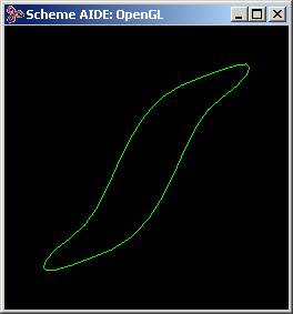
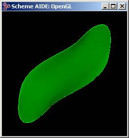
; ds:add-dist-press
; Add a distributed pressure to puff a faces shape
; Build a test square spline face.
; (6x6 control points, x and y side length = 36)
(define dsmodel1 (ds:test-face 6 6 36 36 0))
;; dsmodel1
; Dont display entity / ds test face exists.
(define erase (entity:erase dsmodel1))
;; erase
; Render the loads and constraints.
(ds:set-draw-state dsmodel1 1
(+ ds-draw-cstrns ds-draw-loads))
;; ()
; Add a distributed pressure and solve for new shape.
(define c1 (ds:add-dist-press dsmodel1 1 2000))
;; c1
(ds:solve dsmodel1 1 1)
;; ()
; The square shape, constrained along its edges,
; rises in its center.
; OUTPUT Original
; Increase the pressures amplitude and effect.
(ds:set-load-gain dsmodel1 c1 10000)
;; 3
(ds:solve dsmodel1 1 1)
;; ()
; The center of the surface moves more.
; OUTPUT Result
Figure. ds:add-dist-press
|
[Top]
ds:add-parab-cstrn
- Action
-
Adds a curve constraint along a parabolic arc within the parameter space of a
deformable surface and returns the constraints tag.
-
Filename
-
scm/scmext/ds/dsscm.cpp
-
APIs
-
api_dm_get_attrib_dm2acis
-
Syntax
-
(ds:add-parab-cstrn owner target=1 behavior
start-ppt tang-xsect-ppt stop-ppt
[integral-degree=10]) -
Arg Types
-
-
Returns
-
integer
- Description
-
Adds a curve load to the target deformable model of the owner along a parabolic
arc within the domain of the deformable surface. This function is for
deformable surfaces only.
- The
target
argument specifies which deformable model to use in a patch hierarchy. Valid
values for
target
are:
-
1 = active deformable model
-
2 = root deformable model
-
-1 = active deformable model and offspring
-
-2 = root deformable model and offspring
Otherwise, the target is the deformable model whose tag identifier equals
target.
The parabolic arc runs from
start-ppt
to
stop-ppt
and the arcs end tangents intersect at the point
tang-xsect_ppt. The u and v
values in
start-ppt,
tang-xsect-ppt, and
stop-ppt
are scaled to range from 0.0 to 1.0.
integral-degree
specifies the accuracy of numerical integration used during the construction of
the constraint equations.
behavior
specifies whether the position and/or the tangent of the deformable model
across the curve is constrained along the length of the curve.
- For curve constraints, the allowed behaviors include:
-
- "position" or "p"
-
- "tangent" or "t"
-
- "curvature" or "c"
-
For the combinations:
-
- "pos_tan" or "pt"
-
- "pos_cur" or "pc"
Therefore, a number of different behavior states are allowed for a link
constraint. These states can be specified by the
string
pos_?_?_tan_?_?
where the question marks can be one of
off
or
o,
fixed
or
f, or
linked
or
l. As an example, the string
pos_linked_linked_tan_off_off
or
pll_too
sets the behavior to
DM_POS_LINKED
|
DM_POS_2_LINKED
|
DM_TAN_FREE
|
DM_TAN_2_FREE.
- Arguments
-
owner
is an ACIS face or edge on which the deformable model lives.
-
target
specifies which deformable model to use in a patch hierarchy.
-
behavior
specifies whether the position, the tangent, and/or the curvature of the
deformable model across the curve is constrained along the length of the curve.
-
start-ppt
starting point of parabolic arc.
-
stop-ppt
ending point of parabolic arc.
-
tang-xsect-ppt
points where arcs end tangents intersect.
-
integral-degree
specifies the accuracy of numerical integration used during the construction of
the constraint equations. -
Limitations
-
This is used for deformable surfaces only; it has no effect on deformable
curves.
-
This Scheme extension will not always work correctly if the target argument is
not already the active deformable model. A target deformable model can be made
active by calling a query Scheme extension on it, such as
ds:get-tag-summary or
ds:get-alpha. This should
be used immediately before calling the extension.
; ds:add-parab-cstrn
; Add to a square test face a parabolic crv-load
; and use it.
; Build a test square spline face.
; (6x6 control points, x and y side length = 36)
(define dsmodel1 (ds:test-face 6 6 36 36 0))
;; dsmodel1
; Dont display entity / ds test face exists.
(define erase (entity:erase dsmodel1))
;; erase
; Render the loads and constraints.
(ds:set-draw-state dsmodel1 1
(+ ds-draw-cstrns ds-draw-loads))
;; ()
; Toggle off the default edge crv-cstrns.
(ds:toggle-cstrn dsmodel1 1)
;; 0
(ds:toggle-cstrn dsmodel1 2)
;; 0
(ds:toggle-cstrn dsmodel1 3)
;; 6
(ds:toggle-cstrn dsmodel1 4)
;; 6
; Add corner constraints.
(ds:add-pt-cstrn dsmodel1 1 "position"
(par-pos 1 0))
;; 7
(ds:add-pt-cstrn dsmodel1 1 "position"
(par-pos 1 1))
;; 8
(ds:add-pt-cstrn dsmodel1 1 "position"
(par-pos 0 1))
;; 9
; OUTPUT Original
; Add a parabolic load across the squares corner.
(ds:add-parab-cstrn dsmodel1 1 "position"
(par-pos 0 0.4) (par-pos 0 0)
(par-pos 0.4 0))
;; 10
; Add a pt-cstrn at the center and track it.
(define cc1 (ds:add-pt-cstrn dsmodel1
1 "position" (par-pos 0.5 0.5)))
;; cc1
(ds:set-pt-xyz dsmodel1 cc1 0
(position 18 18 20))
;; 8
; Compute a new deformable model position.
(ds:solve dsmodel1 1 1)
;; ()
; The dsmodel1 deforms to interpolate all the point
; constraints while remaining near the load curve.
; OUTPUT Result
Figure. ds:add-parab-cstrn
|
[Top]
ds:add-parab-load
- Action
-
Adds a curve load along a parabolic arc within the parameter space of the
deformable surface and returns a loads tag.
-
Filename
-
scm/scmext/ds/dsscm.cpp
-
APIs
-
api_dm_get_attrib_dm2acis
-
Syntax
-
(ds:add-parab-load owner target=1 start-ppt
tang-xsect-ppt stop-ppt
[gain=100 integral-degree=10]) -
Arg Types
-
-
Returns
-
integer
- Description
-
Adds a curve load to the target deformable model of the owner along a parabolic
arc within the domain of the deformable surface.
- The
target
argument specifies which deformable model to use in a patch hierarchy. Valid
values for
target
are:
-
1 = active deformable model
-
2 = root deformable model
-
-1 = active deformable model and offspring
-
-2 = root deformable model and offspring
Otherwise, the target is the deformable model whose tag identifier equals
target.
The parabolic arc runs from
start-ppt
to
stop-ppt
and the arcs end tangents intersect at the point
tang-xsect-ppt. The u and v
values in
start-ppt,
tang-xsect-ppt, and
stop-ppt
are scaled to range from 0.0 to 1.0.
gain
specifies the stiffness that attracts the loads domain curve towards its image
space curve. The loads image space curve is made by projecting the domain curve
into image space using the surfaces shape. This starts the curve load out with
two curves that have the same shape.
integral-degree
specifies the accuracy of numerical integration used during the construction of
the constraint equations.
- Arguments
-
owner is an ACIS face or edge on
which the deformable model lives.
-
target
specifies which deformable model to use in a patch hierarchy.
-
start-ppt
starting point of parabolic arc.
-
stop-ppt
ending point of parabolic arc.
-
tang-xsect-ppt
points where arcs end tangents intersect.
-
gain
specifies the stiffness that attracts the loads domain curve towards its image
space curve.
-
integral-degree
specifies the accuracy of numerical integration used during the construction of
the constraint equations. -
Limitations
-
Parabolic load curves may only be added to deformable surfaces. They cannot be
added to deformable curves.
This Scheme extensions will not always work correctly if the target argument is
not already the active deformable model. A target deformable model can be made
active by calling a query Scheme extensions on it, such as
ds:get-tag-summary or
ds:get-alpha. This should
be used immediately before calling the extension.
; ds:add-parab-load
; Add to a square test face a parabolic crv-load
; and use it.
; Build a test square spline face.
; (6x6 control points, x and y side length = 36)
(define dsmodel1 (ds:test-face 6 6 36 36 0))
;; dsmodel1
; Dont display entity / ds test face exists.
(define erase (entity:erase dsmodel1))
;; erase
; Render the loads and constraints.
(ds:set-draw-state dsmodel1 1
(+ ds-draw-cstrns ds-draw-loads))
;; ()
; Toggle off the default edge crv-cstrns.
(ds:toggle-cstrn dsmodel1 1)
;; 0
(ds:toggle-cstrn dsmodel1 2)
;; 0
(ds:toggle-cstrn dsmodel1 3)
;; 6
(ds:toggle-cstrn dsmodel1 4)
;; 6
; Add corner constraints.
(ds:add-pt-cstrn dsmodel1 1 "position"
(par-pos 1 0))
;; 7
(ds:add-pt-cstrn dsmodel1 1 "position"
(par-pos 1 1))
;; 8
(ds:add-pt-cstrn dsmodel1 1 "position"
(par-pos 0 1))
;; 9
; OUTPUT Original
; Add a parabolic load across the squares corner.
(ds:add-parab-load dsmodel1 1
(par-pos 0 0.4) (par-pos 0 0)
(par-pos 0.4 0) 300)
;; 10
; Add a pt-cstrn at the center and track it.
(define cc1 (ds:add-pt-cstrn dsmodel1 1
"position" (par-pos 0.5 0.5)))
;; cc1
(ds:set-pt-xyz dsmodel1 cc1 0
(position 18 18 20))
;; 8
; Compute a new deformable model position.
(ds:solve dsmodel1 1 1)
;; ()
; dsmodel1 deforms to interpolate the point
; constraints while remaining near the load curve.
; OUTPUT Result
Figure. ds:add-parab-load
|
[Top]
ds:add-patch
- Action
-
Adds a patch to a parent deformable model in preparation for local
deformations.
-
Filename
-
scm/scmext/ds/dsscm.cpp
-
APIs
-
api_dm_add_patch,
api_dm_get_attrib_dm2acis
-
Syntax
-
(ds:add-patch owner target=1 shape point1 point2 point3
refinement) -
Arg Types
-
-
Returns
-
integer
- Description
-
Adds a patch to a parent target deformable model in preparation for local
deformations. This returns a tag identifier of the patch newly added to the
deformable model.
- The value of
shape
selects the seam shape of the boundary. The values are:
-
1 = square seam
-
2 = elliptical seam
-
3 = fillet_square seam
-
When
shape
equals 1, a square seam,
point1
and
point2
define the upper and lower corners of the box and the values of
point3, while required, are not used.
When
shape
equals 2, an elliptical seam, the patch is an ellipse defined by the function:
-
W(s) =
point1
+
point2
* cos(s) +
point3
* sin(s)
-
where s ranges from 0 to 2Pi.
The center of the ellipse is
point1. One axis of the ellipse is
defined by the vector
point2, and the second axis of the
ellipse is defined by the vector
point3.
point2
and
point3
are stored as par-pos objects instead of pos-vec objects only because the
pos-vec object has not yet been exposed to the Scheme interface. All point
arguments are par_pos objects. The points
point1,
(point1+point2),
and (point1+point3)
may all have values which range over the unit square which is mapped to the
domain of the actual target deformable model.
When
shape
equals 3, a fillet square seam,
point1
and
point2
define the upper and lower corners of a square seam where each of the squares
corners are rounded off with an arc fillet whose radius equals
point3.
The
refinement
argument specifies the density of the patch control points as compared to the
parents. A
refinement
value of 1 specifies that the new patch control point density is the same as
that of the target deformable model. A
refinement
value of 2 specifies that the new patch has twice the density of control points
as the parent. The
refinement
value must be an integer greater than 0.
- The
target
argument specifies which deformable model to use in a patch hierarchy. Valid
values for
target
are:
-
1 = active deformable model
-
2 = root deformable model
-
-1 = active deformable model and offspring
-
-2 = root deformable model and offspring
Otherwise, the target is the deformable model whose tag identifier equals
target.
- Arguments
-
owner
is an ACIS face or edge on which the deformable model lives.
-
target
specifies which deformable model to use in a patch hierarchy.
-
shape
selects the seam shape of the boundary.
-
point1
specifies particular point depending on the model.
-
point2
specifies particular point depending on the model.
-
point3
specifies particular point depending on the model.
-
refinement
specifies the density of the patch control points as compared to the parents. -
Limitations
-
At present, elliptical patches cannot be added. Face patches must be completely
contained within the interior of their parents. That is, the boundary of the
child may not touch or overlap the boundary of its parent.
; ds:add-patch
; Create deformable topology/geometry to illustrate
; command.
(define dsmodel1 (ds:test-face 6 6 36 36 0))
;; dsmodel1
(define cc1 (ds:add-pt-cstrn dsmodel1
1 "position" (par-pos 0.5 0.5)))
;; cc1
(ds:set-pt-xyz dsmodel1 cc1 0
(position 18 18 10))
;; 8
(ds:solve dsmodel1 1 1)
;; ()
; Add patch to deformable model.
(define patch1 (ds:add-patch dsmodel1 1 1
(par-pos 0.3 0.3) (par-pos 0.5 0.5)
(par-pos 0.7 0.7) 3))
;; patch1
|
[Top]
ds:add-pt-cstrn
- Action
-
Adds a point constraint to the specified deformable model of the owner.
-
Filename
-
scm/scmext/ds/dsscm.cpp
-
APIs
-
api_dm_get_attrib_dm2acis
-
Syntax
-
(ds:add-pt-cstrn owner target=1 behavior
{uv-position | pick-event}) -
Arg Types
-
-
Returns
-
integer
- Description
-
Adds a point constraint to the target deformable surface of the owner and
returns the new constraints tag identifier.
- The
target
argument specifies which deformable model to use in a patch hierarchy. Valid
values for
target
are:
-
1 = active deformable model
-
2 = root deformable model
Otherwise, the target is the deformable model whose tag identifier equals
target.
When a parametric position location is supplied for
uv-position, the point constraint is
added at the given parametric location. The u and v values in
uv-position
are scaled to range from 0.0 to 1.0.
-
behavior
specifies whether the position, the tangent, and/or the curvature of the
deformable model across the curve is constrained along the length of the curve.
The valid string values for
behavior
are:
-
- for single behaviors:
-
- "position" or "p"
-
- "tangent" or "t"
-
- "tan2" or "t2"
-
- "normal" or "n"
-
- "binormal" or "b"
-
- "curvature" or "c"
-
- "curv2" or "c2"
-
for 2 behavior combinations:
-
- "pos_tan" or "pt"
-
- "pos_tan2" or "pt2"
-
- "pos_norm" or "pn"
-
- "pos_binorm" or "pb"
-
- "pos_cur" or "pc"
-
- "pos_cur2" or "pc2"
-
- "tan_tan2" or "tt2"
-
- "tan_norm" or "tn"
-
- "tan_binorm" or "tb"
-
- "tan2_norm" or "t2n"
-
- "cur_cur2" or "cc2"
-
for 3 behavior combinations:
-
- "pos_tan_tan2" or "ptt2"
-
- "pos_tan_norm" or "ptn"
-
- "pos_tan_binorm" or "ptb"
-
- "pos_tan2_norm" or "pt2n"
-
- "pos_tan2_cur" or "pt2c"
-
- "pos_tan_cur2" or "ptc2"
-
- "pos_cur_cur2" or "pcc2"
-
- "tan_tan2_norm" or "tt2n"
-
- "pos_tan_tan2_norm" or "ptt2n"
Therefore, a large number of different behavior states are allowed for a link
constraint. These states can be specified by the
string
pos_?_?_tan_?_?
where the question marks can be one of
off
or
o,
fixed
or
f, or
linked
or
l. As an example, the string
pos_linked_linked_tan_off_off
or
pll_too
sets the behavior to
DM_POS_LINKED
|
DM_POS_2_LINKED
|
DM_TAN_FREE
|
DM_TAN_2_FREE.
Trimmed surfaces occupy only a portion of the unit square. An error is generated
if the
uv-position
is not in a valid portion of the deformable model. When the
pick-event
is supplied, a point constraint is added at the first intersection between a
ray and the deformable surface or curve. The ray starts at the pick point and
moves in the viewing direction.
- Arguments
-
owner
is an ACIS face or edge on which the deformable model lives.
-
target
specifies which deformable model to use in a patch hierarchy.
-
behavior
specifies whether the position, the tangent, and/or the curvature of the
deformable model across the curve is constrained along the length of the curve.
-
uv-position
is a parametric position location.
-
pick-event to add point
constraint at the first intersection between a ray and the deformable surface
or curve.
; ds:add-pt-cstrn
; Add and use a point constraint to a square test
; Build a test square spline face.
; (6x6 control points, x and y side length = 36)
(define dsmodel1 (ds:test-face 6 6 36 36 0))
;; dsmodel1
; Dont display entity / ds test face exists
(define erase (entity:erase dsmodel1))
;; erase
; Render the loads and constraints.
(ds:set-draw-state dsmodel1 1
(+ ds-draw-cstrns ds-draw-loads))
;; ()
; OUTPUT Original
; Add a pt-cstrn at the center and track it
(define cc1 (ds:add-pt-cstrn dsmodel1
1 "position" (par-pos 0.5 0.5)))
;; cc1
(ds:set-pt-xyz dsmodel1 cc1 0 (position 16 16 10))
;; 8
; Compute a new deformable model position
(ds:solve dsmodel1 1 1)
;; ()
; OUTPUT Result
Figure. ds:add-pt-cstrn
|
[Top]
ds:add-pt-press
- Action
-
Adds a point pressure load to the deformable model of the owner and returns its
tag.
-
Filename
-
scm/scmext/ds/dsscm.cpp
-
APIs
-
api_dm_get_attrib_dm2acis
-
Syntax
-
(ds:add-pt-press owner target=1 {uv-position | pick} gain=100)
-
Arg Types
-
-
Returns
-
integer
- Description
-
Returns the tag identifier of a point pressure added to the target deformable
surface of the owner.
- The
target
argument specifies which deformable model to use in a patch hierarchy. Valid
values for
target
are:
-
1 = active deformable model
-
2 = root deformable model
-
-1 = active deformable model and offspring
-
-2 = root deformable model and offspring
Otherwise, the target is the deformable model whose tag identifier equals
target.
The point pressure is a single force vector acting in the direction of the
surfaces normal with an amplitude set by the input gain. The uv location
of the force on the surface is specified explicitly by
uv-position
or by defining a pick-event. The u and v values in
uv-position
are scaled to range from 0.0 to 1.0. When a pick-event is input, a line passing
through the
pick
point in the viewing direction is intersected with the surface to find the
point at which the pressure is applied.
- Arguments
-
owner
ACIS face or edge on which the deformable model lives.
-
target
specifies which deformable model to use in a patch hierarchy.
-
uv-position
is the u and v position values.
-
pick
is a pick event.
-
gain
is a measure of how strongly the load pulls the deformable model to its target.
; ds:add-pt-press
; Use a point pressure load to puff a faces shape
; Build a test square spline face.
; (6x6 control points, x and y side length = 36)
(define dsmodel1 (ds:test-face 6 6 36 36 0))
;; dsmodel1
; Dont display entity / ds test face exists
(define erase (entity:erase dsmodel1))
;; erase
; Render the loads and constraints.
(ds:set-draw-state dsmodel1 1
(+ ds-draw-cstrns ds-draw-loads))
;; ()
(define c1 (ds:add-spring dsmodel1 1
(par-pos 0.5 0.5) (position 10 10 15) 200))
;; c1
; Add a point pressure load and
; solve for the new shape
(ds:add-pt-press dsmodel1 1
(par-pos 0.4 0.8) 10000))
;; 7
(ds:solve dsmodel1 1 1)
;; ()
; OUTPUT Original
; The square shape, constrained along its edges
; rises towards one corner
; Increase the gain for a larger motion
(ds:set-load-gain dsmodel1 c1 20000)
;; 4
(ds:solve dsmodel1 1 1)
;; ()
; Motion is exaggerated.
; Commit the deformable surface back to the model.
(ds:commit dsmodel1)
;; ()
; Perform a zoom-all to see everything. This
; is part of acis.scm.
(zoom-all)
;; #[view 10768947]
; OUTPUT Result
Figure. ds:add-pt-press
|
[Top]
ds:add-spring
- Action
-
Adds a spring load to the deformable model of an owner and returns its tag.
-
Filename
-
scm/scmext/ds/dsscm.cpp
-
APIs
-
api_dm_get_attrib_dm2acis
-
Syntax
-
(ds:add-spring owner target=1 {uv-position | pick} [xyz-position]
gain=100 [slide-state=0]) -
Arg Types
-
-
Returns
-
integer
- Description
-
Returns the tag identifier of a spring load added to the target deformable
surface of an owner input face.
- The
target
argument specifies which deformable model to use in a patch hierarchy. Valid
values for
target
are:
-
1 = active deformable model
-
2 = root deformable model
-
-1 = active deformable model and offspring
-
-2 = root deformable model and offspring
Otherwise, the target is the deformable model whose tag identifier equals
target.
- A spring load is a force that acts on a point in the surface in the direction
of a point in three dimensional space with
-
Amplitude = gain * (distance between the two points)**2
This force acts to keep the point in the surface near its associated three
dimensional space point. Increasing the gain value keeps the two points closer
together. Use the point constraint feature to force a point on the surface to
interpolate a point in three dimensional space. The location of the point in
the surface can be given explicitly by the
uv-position
par-pos or computed from a pick-event. Deformable curves only use the u component
of the input par-pos object. The u and v values in
uv-position
are scaled to range from 0.0 to 1.0.
When a pick-event is used, a line passing through the
pick
point in the viewing direction is intersected with the surface to compute the
surface location for the spring. The three dimensional space point may be given
explicitly by including the input position xyz-position. When xyz-position is
omitted, the springs
uv-position
point is projected into three dimensional space through the surfaces shape to
find the springs (x,y,z) position.
Springs may slide within the deformable surface so that they tend to act in a
direction normal to the surface. If
slide-state
is 0 (default), the spring is fixed in the surface; if
slide-state
is 1, the spring is allowed to slide in the surface.
Use point constraints to force a point on the surface to interpolate a point in
three dimensional space.
- Arguments
-
owner
is an ACIS face or edge on which the deformable model lives.
-
target
specifies which deformable model to use in a patch hierarchy.
-
uv-position
is the location of the point in the surface where force is applied.
-
pick
is a pick event.
-
gain
is a measure of how strongly the load pulls the deformable model to its target.
-
xyz-position
input position in the three dimensional space for the springs position.
-
slide-state
is an integer value which specifies whether the spring is fixed or sliding.
; ds:add-spring
; Use a spring load to puff a faces shape
; Build a test square spline face.
; (6x6 control points, x and y side length = 36)
(define dsmodel1 (ds:test-face 6 6 36 36 0))
;; dsmodel1
; remove entity / ds test face exists
(define erase (entity:erase dsmodel1))
;; erase
; Add a spring and solve for the new shape
(define c1 (ds:add-spring dsmodel1 1
(par-pos 0.5 0.5) (position 18 18 15) 100))
;; c1
(ds:solve dsmodel1 1 1)
;; ()
; OUTPUT Original
; The square shape, constrained along its edges rises
; at its center
; Move the springs xyz pt and see the affect
(ds:set-pt-xyz dsmodel1 c1 0
(position 25 25 15))
;; 4
(ds:solve dsmodel1 1 1)
;; ()
; The center of the surface moves to the side
; OUTPUT Result
Figure. ds:add-spring
|
[Top]
ds:add-spring-curve
- Action
-
Adds a curve load between a straight parameter curve and a line, or between a
parameter curve line and an ellipse.
-
Filename
-
scm/scmext/ds/dsscm.cpp
-
APIs
-
api_dm_get_attrib_dm2acis
-
Syntax
-
(ds:add-spring-curve owner target=1 pos-param1 pos-param2
{{position1 position2} | {positionc positiona positionb}}
[gain=100 integral-degree=10]) -
Arg Types
-
-
Returns
-
integer
- Description
-
Builds and returns the tag identifier of a curve load acting between a
parameter curve line in the surface of the target and a three dimensional line,
or between a parameter curve line in the surface of the target and an ellipse.
- The
target
argument specifies which deformable model to use in a patch hierarchy. Valid
values for
target
are:
-
1 = active deformable model
-
2 = root deformable model
-
-1 = active deformable model and offspring
-
-2 = root deformable model and offspring
Otherwise, the target is the deformable model whose tag identifier equals
target.
The load causes the line in the surface to lie near the shape of the three
dimensional curve during subsequent deformations. This load is helpful in
forcing the shape of the overall surface.
- owner identifies the owning entity of the deformable model to be modified. The
par-pos,
pos-param1
and pos-param2 mark the end points of a straight pcurve in the deformable
surface. The u and v values in
pos-param1
and
pos-param2
are scaled to range from 0.0 to 1.0. The three dimensional space curve type is
specified by the number of positions entered. Entering two positions, position1
and position2, causes the command to build a three dimensional space line from
point position1 to position2. Entering three positions causes the system to
build a closed elliptical three dimensional space curve centered on
positionc
with minimum and maximum radii specified by the vectors
positiona
and
positionb. The equation of the ellipse
is:
-
Ellipse(s) = pc + cos(s) pa + sin(s) pb - where
s is 0 <= s <= 1.
gain
specifies the stiffness of the spring acting between the pcurve and the three
dimensional space curve. Large
gain
values cause the points along the pcurve to lie closer to the points on the
three dimensional space curve during subsequent deformations.
integral-degree
specifies the accuracy of numerical integration used within each element. (A
polynomial function of degree
integral-degree
will be integrated exactly.) Increasing the
integral-degree
increases the computation cost and reduces the error.
- Arguments
-
owner
is an ACIS face or edge on which the deformable model lives.
-
target
specifies which deformable model to use in a patch hierarchy.
-
pos-param1
start point of a straight pcurve in the deformable surface.
-
pos-param2
end points of a straight pcurve in the deformable surface.
-
position1
specifies a position to build a three dimensional space line from point
position1
to
position2.
-
position2
specifies a position to build a three dimensional space line from point
position1
to
position2.
-
positionc
specifies a position to build a closed elliptical three dimensional space curve
centered on
positionc
with minimum and maximum radii specified by the vectors
positiona
and
positionb.
-
positionb
specifies a position to build a closed elliptical three dimensional space curve
centered on
positionc
with minimum and maximum radii specified by the vectors
positiona
and
positionb.
-
positiona
specifies a position to build a closed elliptical three dimensional space curve
centered on
positionc
with minimum and maximum radii specified by the vectors
positiona
and
positionb.
-
gain
specifies the stiffness of the spring acting between the pcurve and the three
dimensional space curve.
-
integral-degree
specifies the accuracy of numerical integration used within each element. -
Limitations
-
This Scheme extensions will not always work correctly if the target argument is
not already the active deformable model. A target deformable model can be made
active by calling a query Scheme extensions on it, such as
ds:get-tag-summary or
ds:get-alpha. This should
be used immediately before calling the extension.
; ds:add-spring-curve
; Build a test square spline face.
; (6x6 control points, x and y side length = 36)
(define dsmodel1 (ds:test-face 6 6 36 36 0))
;; dsmodel1
; Dont display entity / ds test face exists
(define erase (entity:erase dsmodel1))
;; erase
; Render the loads and constraints.
(ds:set-draw-state dsmodel1 1
(+ ds-draw-cstrns ds-draw-loads))
;; ()
; Add a spring and solve for the new shape
(define c1 (ds:add-spring-curve dsmodel1 1
(par-pos 0 0.5) (par-pos 0.5 0)
(position 0 18 10) (position 18 0 20) 10000))
;; c1
; OUTPUT Original
; Toggle off the default crv-cstrns
(ds:toggle-cstrn dsmodel1 1)
;; 0
(ds:toggle-cstrn dsmodel1 2)
;; 0
(ds:toggle-cstrn dsmodel1 3)
;; 6
(ds:toggle-cstrn dsmodel1 4)
;; 6
; Add some corner point constraints.
(ds:add-pt-cstrn dsmodel1 1 "position"
(par-pos 0 0))
;; 8
(ds:add-pt-cstrn dsmodel1 1 "position"
(par-pos 0 1))
;; 9
(ds:add-pt-cstrn dsmodel1 1 "position"
(par-pos 1 1))
;; 10
(ds:add-pt-cstrn dsmodel1 1 "position"
(par-pos 1 0))
;; 11
; Compute a new deformable model position.
(ds:solve dsmodel1 1 1)
;; ()
; The dsmodel1 deforms to interpolate the corner
; points and to lie near the crv-load.
; OUTPUT Result
Figure. ds:add-spring-curve
|
[Top]
ds:add-spring-set
- Action
-
Adds a spring set to the deformable model and returns its tag.
-
Filename
-
scm/scmext/ds/dsscm.cpp
-
APIs
-
api_dm_get_attrib_dm2acis
-
Syntax
-
(ds:add-spring-set owner target=1 [domain-points] position gain)
-
Arg Types
-
-
Returns
-
integer
- Description
-
Returns the tag identifier of a spring set added to the target deformable
surface from the owner entity.
The
target
argument specifies which deformable model to use in a patch hierarchy. Valid
values for
target
are:
-
1 = active deformable model
-
2 = root deformable model
-
-1 = active deformable model and offspring
-
-2 = root deformable model and offspring
Otherwise, the target is the deformable model whose tag identifier equals
target.
The
domain-points
array is interpreted as follows:
-
case 1d: [u0, u1, ... un]
case 2d: [u0, v0, u1, v1, ... un, vn]
This Scheme extension is only provided to demonstrate the idea of how spring
sets can shape deformable surfaces. They are for creating surface descriptions
from scattered point sets. The success of the operation depends on a good
mapping of image space points to domain locations on the surface. This
extension hard codes a very simple mapping. x and y values are
mapped directly to u and v values. To try this capability, create
point sets that span an xy square and vary in z.
- Arguments
-
owner
is an ACIS face or edge on which the deformable model lives.
-
target
specifies which deformable model to use in a patch hierarchy.
-
domain-points
specifies the array of points.
-
position
specifies the surface position.
-
gain is a measure of how strongly
the load pulls the deformable model to its target.
; ds:add-spring-set
; Example command for demonstrating how a deformable
; model can be used to generate a surface shape
; from a set of scattered points.
; Build a test square spline face.
; (12x12 control points, x and y side length = 36)
(define dsmodel1 (ds:test-face 12 12 36 36 0))
;; dsmodel1
; Dont display entity / ds test face exists
(define erase (entity:erase dsmodel1))
;; erase
; Render the loads and constraints.
(ds:set-draw-state dsmodel1 1
(+ ds-draw-cstrns ds-draw-loads))
;; ()
(ds:set-default-shape dsmodel1 1 0)
;; ()
; toggle the edge constraints
(ds:toggle-cstrn dsmodel1 1)
;; 0
(ds:toggle-cstrn dsmodel1 2)
;; 0
(ds:toggle-cstrn dsmodel1 3)
;; 6
(ds:toggle-cstrn dsmodel1 4)
;; 6
; Sample a simple surface function at a set of
; random points and connect each point to
; the deformable surface with a spring.
(define spr1 (ds:add-spring-set dsmodel1 1
(ds:test-scatter 65 36 36 25) 5000))
;; spr1
; OUTPUT Original
; Force the surface to deform to the points.
(ds:solve dsmodel1 1 1)
;; ()
; Increase the spring gain and solve again.
(ds:set-load-gain dsmodel1 spr1 30000)
;; 5
(ds:solve dsmodel1 1 1)
;; ()
; Refine the rendering to improve the look
(ds:set-draw-grid dsmodel1 1 30 30)
;; ()
; OUTPUT Result
Figure. ds:add-spring-set
|
[Top]
ds:add-str-cstrn
- Action
-
Adds a curve constraint that is a straight line in the parametric space of the
deformable model and returns its tag.
-
Filename
-
scm/scmext/ds/dsscm.cpp
-
APIs
-
api_dm_get_attrib_dm2acis
-
Syntax
-
(ds:add-str-cstrn owner target=1 behavior
start-point stop-point [integral-degree=10]) -
Arg Types
-
-
Returns
-
integer
- Description
-
Adds a curve constraint to the target deformable model of the owner along a
straight line segment within the domain of the deformable surface. The line
runs from
start-point
to
stop-point.
-
- The
target
argument specifies which deformable model to use in a patch hierarchy. Valid
values for
target
are:
-
1 = active deformable model
-
2 = root deformable model
-
-1 = active deformable model and offspring
-
-2 = root deformable model and offspring
Otherwise, the target is the deformable model whose tag identifier equals
target.
For deformable curves only the u values of the input par-pos objects are
used. The u and v values in start-point and stop-point are scaled
to range from 0.0 to 1.0.
integral-degree
specifies the accuracy of numerical integration used within each element. (A
polynomial function of degree
integral-degree
will be integrated exactly.) Increasing the
integral-degree
increases the computation cost and reduces the error.
-
behavior
specifies whether the position and/or the tangent of the deformable model
across the curve is constrained along the length of the curve. The valid string
values for
behavior
are:
- For curve constraints allowed behaviors include:
-
- "pos_tan" or "pt"
-
- "pos_cur" or "pc" (turns on tangent)
- Arguments
-
owner
ACIS face or edge on which the deformable model lives.
-
target
specifies which deformable model to use in a patch hierarchy.
-
start-point
is the starting point of a line.
-
stop-point
is the ending point of a line.
-
behavior
specifies whether the position, the tangent, and/or the curvature of the
deformable model across the curve is constrained along the length of the curve.
-
integral-degree
specifies the accuracy of numerical integration used within each element. -
Limitations
-
This Scheme extensions will not always work correctly if the target argument is
not already the active deformable model. A target deformable model can be made
active by calling a query Scheme extensions on it, such as
ds:get-tag-summary or
ds:get-alpha. This should
be used immediately before calling the extension.
; ds:add-str-cstrn
; Add to a square test face a straight crv-cstrn
; and use it.
; Build a test square spline face.
; (6x6 control points, x and y side length = 36)
(define dsmodel1 (ds:test-face 6 6 36 36 0))
;; dsmodel1
; Dont display entity / ds test face exists
(define erase (entity:erase dsmodel1))
;; erase
; Render the loads and constraints.
(ds:set-draw-state dsmodel1 1
(+ ds-draw-cstrns ds-draw-loads))
;; ()
; toggle off the default edge crv-cstrns
(ds:toggle-cstrn dsmodel1 1)
;; 0
(ds:toggle-cstrn dsmodel1 2)
;; 0
(ds:toggle-cstrn dsmodel1 3)
;; 6
(ds:toggle-cstrn dsmodel1 4)
;; 6
; Add in corner constraints
(ds:add-pt-cstrn dsmodel1 1 "position"
(par-pos 1 0))
;; 7
(ds:add-pt-cstrn dsmodel1 1 "position"
(par-pos 1 1))
;; 8
(ds:add-pt-cstrn dsmodel1 1 "position"
(par-pos 0 1))
;; 9
; Add straight constraint across squares corner
(ds:add-str-cstrn dsmodel1 1 "position"
(par-pos 0 0.4) (par-pos 0.4 0))
;; 10
; Add a pt-cstrn at the center and track it
(define cc1 (ds:add-pt-cstrn dsmodel1
1 "position" (par-pos 0.5 0.5)))
;; cc1
(ds:set-pt-xyz dsmodel1 cc1 0
(position 18 18 20))
;; 8
; OUTPUT Original
; Compute a new deformable model position
(ds:solve dsmodel1 1 1)
;; ()
; The dsmodel1 deforms to interpolate
; all the point and the curve constraints
; OUTPUT Result
Figure. ds:add-str-cstrn
|
[Top]
ds:add-str-load
- Action
-
Adds a curve load to a deformable model along a straight parametric line and
returns the loads tag.
-
Filename
-
scm/scmext/ds/dsscm.cpp
-
APIs
-
api_dm_get_attrib_dm2acis
-
Syntax
-
(ds:add-str-load owner target=1 start-point stop-point
| [gain=100 integral-degree=10]) |
-
Arg Types
-
-
Returns
-
integer
- Description
-
Adds a curve load to target deformable model of the owner along a straight line
segment within the domain of the deformable surface.
- The
target
argument specifies which deformable model to use in a patch hierarchy. Valid
values for
target
are:
-
1 = active deformable model
-
2 = root deformable model
-
-1 = active deformable model and offspring
-
-2 = root deformable model and offspring
Otherwise, the target is the deformable model whose tag identifier equals
target.
The line runs from
start-point
to
stop-point. The u and v values
in
start-point
and
stop-point
are scaled to range from 0.0 to 1.0. The loads image space curve is made by
projecting the domain curve into image space using the surfaces shape. This
starts the curve load out with two curves that have the same shape.
integral-degree
specifies the accuracy of numerical integration used within each element. (A
polynomial function of degree
integral-degree
will be integrated exactly.) Increasing the
integral-degree
increases the computation cost and reduces the error
- Arguments
-
owner
is an ACIS face or edge on which the deformable model lives.
-
target
specifies which deformable model to use in a patch hierarchy.
-
start-point
is the starting point of a line.
-
stop-point
is the ending point of a line.
-
gain
is a measure of how strongly the load pulls the deformable model to its target.
-
integral-degree
specifies the accuracy of numerical integration used within each element. -
Limitations
-
This Scheme extensions will not always work correctly if the target argument is
not already the active deformable model. A target deformable model can be made
active by calling a query Scheme extensions on it, such as
ds:get-tag-summary or
ds:get-alpha. This should
be used immediately before calling the extension.
; ds:add-str-load
; Add to a square test face a straight crv-load
; and use it.
; Build a test square spline face.
; (6x6 control points, x and y side length = 36)
(define dsmodel1 (ds:test-face 6 6 36 36 0))
;; dsmodel1
; Dont display entity / ds test face exists
(define erase (entity:erase dsmodel1))
;; erase
; Render the loads and constraints.
(ds:set-draw-state dsmodel1 1
(+ ds-draw-cstrns ds-draw-loads))
;; ()
; toggle off the default edge crv-cstrns
(ds:toggle-cstrn dsmodel1 1)
;; 0
(ds:toggle-cstrn dsmodel1 2)
;; 0
(ds:toggle-cstrn dsmodel1 3)
;; 6
(ds:toggle-cstrn dsmodel1 4)
;; 6
; Add in corner constraints
(ds:add-pt-cstrn dsmodel1 1 "position"
(par-pos 1 0))
;; 7
(ds:add-pt-cstrn dsmodel1 1 "position"
(par-pos 1 1))
;; 8
(ds:add-pt-cstrn dsmodel1 1 "position"
(par-pos 0 1))
;; 9
; OUTPUT Original
; Add a parabolic constraint across the
; squares corner
(ds:add-str-load dsmodel1 1 (par-pos 0 0.4)
(par-pos 0.4 0) 200)
;; 10
; Add a pt-cstrn at the center and track it
(define cc1 (ds:add-pt-cstrn dsmodel1 1
"position" (par-pos 0.5 0.5)))
;; cc1
(ds:set-pt-xyz dsmodel1 cc1 0
(position 18 18 20))
;; 8
; Compute a new deformable model position
(ds:solve dsmodel1 1 1)
;; ()
; dsmodel1 deforms to interpolate
; all the point constraints while staying near the
; curve load
; OUTPUT Result
Figure. ds:add-str-load
|
[Top]
ds:add-vector-load
- Action
-
Adds a vector load argument to a deformable model and returns the new vector
loads tag identifier.
-
Filename
-
scm/scmext/ds/dsscm.cpp
-
APIs
-
api_dm_get_attrib_dm2acis
-
Syntax
-
(ds:add-vector-load owner target=1 [image-vector]
gain=100) -
Arg Types
-
-
Returns
-
unspecified
- Description
-
The
target
argument specifies which deformable model to use in a patch hierarchy. Valid
values for
target
are:
-
1 = active deformable model
-
2 = root deformable model
-
-1 = active deformable model and offspring
-
-2 = root deformable model and offspring
Otherwise, the target is the deformable model whose tag identifier equals
target.
A vector load is a constant vector force applied to the entire deformable shape.
This load can be used to simulate a gravity-like effect. The input argument
image-vector
is optional. When given, it is used to define the direction of the vector load.
When omitted, the direction is taken as the surface normal for the center of
the deformable model.
- Arguments
-
owner
is an ACIS face or edge on which the deformable model lives.
-
target
specifies which deformable model to use in a patch hierarchy.
-
gain
is a measure of how strongly the load pulls the deformable model to its target.
-
image-vector
defines the direction of the vector load.
; ds:add-vector-load
; Use a vector_load to puff a faces shape
; define some helpful globals
; Build a test square spline face
; (6x6 control points, x and y side length = 36)
(define dsmodel1 (ds:test-face 6 6 36 36 0))
;; dsmodel1
(define erase (entity:erase dsmodel1))
;; erase
; Dont render the face
; Add a vector_load and solve for the new shape
(define c1 (ds:add-vector-load dsmodel1 2 100))
;; c1
(ds:solve dsmodel1 1 1)
;; ()
; OUTPUT Original
; The square shape, constrained along its edges
; rises at its center
; Move the vector_loads xyz pt and see the affect
(ds:set-pt-xyz dsmodel1 c1 0 (position 25 25 15))
;; 14
(ds:solve dsmodel1 1 1)
;; ()
; The center of the surface moves to the side
; OUTPUT Result
Figure. ds:add-vector-load
|
[Top]
ds:adm-options
- Action
-
This extension returns an
adm-options
object for use in
ds:start-adm.
-
Filename
-
scm/scmext/ds/dsscm.cpp
-
APIs
-
None
-
Syntax
-
(ds:adm-options name-of-option
-
Arg Types
-
-
Returns
-
adm-options
-
Description
This extension returns an
adm-options
object for use in
ds:start-adm
and
ds:add-link. This allows the use of
legacy algorithms in subsequent adm operations.
Errors
-
use_boundary_loads
option requires integer argument.
-
trim_faces
option requires integer argument.
-
Incorrect adm option.
-
Arguments
-
name-of-option
is a string containing the name of the option.
-
value
is an integer value containing the value of option.
-
options
is the different adm-options.
; ds:adm-options
; Create a block
(define b1 (solid:block
(position 5 10 15) (position 10 20 30)))
;; b1
; define adm options
(define ao1 (ds:adm-options "trim_faces" 0))
;; ao1
(define ao2
(ds:adm-options "use_boundary_loads" 0))
;; ao2
; pick a face
(ray:queue 8.00781 14.6484 500 0 0 -1 1)
;; #[ray (8.00781 14.6484 500) (0 0 -1)]
(define ds-model (pick-face))
;; ds-model
; start adm
(ds:start-adm ds-model)
;; #t
|
[Top]
ds:commit
- Action
-
Copies a deformable model shape and data back to its ACIS owner.
-
Filename
-
scm/scmext/ds/dsscm.cpp
-
APIs
-
api_dm_commit_attrib_dm2acis,
api_dm_get_attrib_dm2acis
-
Syntax
-
(ds:commit owner)
-
Arg Types
-
-
Returns
-
unspecified
- Description
-
Replaces the
owner
shape data with the shape of the deformable model. Also saves all the
deformable model data used to create this shape as an
ATTRIB_DSMODEL
attribute associated with the owner. When the owner already has an
ATTRIB_DSMODEL, it overwrites its data
with the current deformable model data. The information in
ATTRIB_DSMODEL
allows the sculpting to be resumed at the same state in the future.
- Arguments
-
owner
ACIS face or edge on which the deformable model lives.
; ds:commit
; Copy a deformable surface model shape and
; deformable model data back to its ACIS face.
; Build a test square spline face.
; (6x6 control points, x and y side length = 36)
(define dsmodel1 (ds:test-face 6 6 36 36 0))
;; dsmodel1
(ds:commit dsmodel1)
;; ()
; No external graphical differences are seen on the
; screen but the internal data structures are now
; different.
; Another Example
; Do not display entity / ds test face exists
(define erase (entity:erase dsmodel1))
;; erase
; Render the loads and constraints.
(ds:set-draw-state dsmodel1 1
(+ ds-draw-cstrns ds-draw-loads) )
;; ()
; Add a circular constraint at the square's center
(ds:add-circ-cstrn dsmodel1 1 "position"
(par-pos 0.5 0.5) (par-pos 0 0.3)
(par-pos 0.3 0))
;; 7
; toggle off the default crv-cstrns
(ds:toggle-cstrn dsmodel1 1)
;; 0
(ds:toggle-cstrn dsmodel1 2)
;; 0
(ds:toggle-cstrn dsmodel1 3)
;; 6
(ds:toggle-cstrn dsmodel1 4)
;; 6
; Add a pt-cstrn at the center and track it
(define cc1 (ds:add-pt-cstrn dsmodel1 1
"position" (par-pos 0.5 0.5)))
;; cc1
(ds:set-pt-xyz dsmodel1 cc1 0 (position 16 16 10))
;; 8
; Compute a new deformable model position
(ds:solve dsmodel1 1 1)
;; ()
; dsmodel1 deforms to interpolate
; both the point and the curve constraint.
; Commit the deformable surface back to the model.
(ds:commit dsmodel1)
;; ()
; Perform a zoom-all to see everything. This
; is part of acis.scm.
(zoom-all)
;; #[view 10768947] |
[Top]
ds:crv-cstrn-from-load
- Action
-
Converts a curve load into a curve constraint and returns the curve constraints
tag.
-
Filename
-
scm/scmext/ds/dsscm.cpp
-
APIs
-
api_dm_get_attrib_dm2acis
-
Syntax
-
(ds:crv-cstrn-from-load owner tag memory=remember)
-
Arg Types
-
-
Returns
-
integer
- Description
-
Converts a curve load into a curve constraint. tag defines the tag ID for the
cstrn to be converted.
memory
can be "r" for remember or "f" for forget. Returns the
tag
identifier of the converted object.
The curve load is converted into a curve constraint, keeping the same tag ID and
behaviors. When
memory
is remember, the constraint has the same target as the load. When
memory
is forget, the constraints target curve is generated by projecting the
parameter space curve into image space through the surface function. In this
case, the surface is constrained to maintain its current position all along the
parameter space curve.
- Arguments
-
owner
ACIS face or edge on which the deformable model lives.
-
tag
defines the tag ID for the cstrn to be converted.
-
memory
is "r" for remember or "f" for forget.
; ds:crv-cstrn-from-load
; Add a crv-load which forces a line in a surface to
; lie near a 3-space line then convert it to a
; constraint.
; Build a test square spline face.
; (6x6 control points, x and y side length = 36)
(define dsmodel1 (ds:test-face 6 6 36 36 0))
;; dsmodel1
; Dont display entity / ds test face exists
(define erase (entity:erase dsmodel1))
;; erase
; Render the loads and constraints.
(ds:set-draw-state dsmodel1 1
(+ ds-draw-cstrns ds-draw-loads))
;; ()
; Add a spline to a 3-space line crv-load
(define cc1 (ds:add-spring-curve dsmodel1 1
(par-pos 0 0.5) (par-pos 0.5 0)
(position 0 18 10) (position 18 0 20) 1000))
;; cc1
; toggle off the default crv-cstrns
(ds:toggle-cstrn dsmodel1 1)
;; 0
(ds:toggle-cstrn dsmodel1 2)
;; 0
(ds:toggle-cstrn dsmodel1 3)
;; 6
(ds:toggle-cstrn dsmodel1 4)
;; 6
; Add some corner point constraints
(define cc2 (ds:add-pt-cstrn dsmodel1 1
"position" (par-pos 0 0)))
;; cc2
(ds:add-pt-cstrn dsmodel1 1
"position" (par-pos 0 1))
;; 9
(ds:add-pt-cstrn dsmodel1 1
"position" (par-pos 1 1))
;; 10
(ds:add-pt-cstrn dsmodel1 1
"position" (par-pos 1 0))
;; 11
; Compute a new deformable model position
(ds:solve dsmodel1 1 1)
;; ()
; OUTPUT Original
; Convert the load to a constraint
(ds:crv-cstrn-from-load dsmodel1 cc1 "forget")
;; 7
; OUTPUT Result
Figure. ds:crv-cstrn-from-load
|
[Top]
ds:crv-load-from-cstrn
- Action
-
Creates a curve load from a topological curve constraint or converts a
user-added curve constraint into a curve load.
-
Filename
-
scm/scmext/ds/dsscm.cpp
-
APIs
-
api_dm_get_attrib_dm2acis
-
Syntax
-
(ds:crv-load-from-cstrn owner tag memory=remember)
-
Arg Types
-
-
Returns
-
integer
- Description
-
Converts a curve constraint into a curve load.
tag
defines the tag ID for the cstrn to be converted.
memory
can be "r", "remember", "f", or "forget". Returns the
tag
identifier of the converted object.
When the constraint is user-added, it is converted into a curve load, keeping
the same tag ID and behaviors. If it is a sheet boundary constraint, a new
curve load is created and the constraint is disabled. The loads parameter space
curve lying within the surface is taken from the curve constraints parameter
space curve. If the curve constraint has a target and the
memory
argument is remember, the load has the same target as the constraint.
Otherwise, the loads image space curve is generated by projecting the parameter
space curve into image space through the surface function. In this case, the
two curves of the curve load start out at the same location.
- Arguments
-
owner
ACIS face or edge on which the deformable model lives.
-
tag
defines the tag ID for the cstrn to be converted.
-
memory
is "r" for remember or "f" for forget.
; ds:crv-load-from-cstrn
; Builds a crv-load from a crv-cstrn.
; Returns the crv-cstrns tag.
; Build a test square face with some tag objects
; (6x6 control points, x and y side length = 36)
(define dsmodel1 (ds:test-face 6 6 36 36 0))
;; dsmodel1
; Dont display entity / ds test face exists
(define erase (entity:erase dsmodel1))
;; erase
; Render the loads and constraints.
(ds:set-draw-state dsmodel1 1
(+ ds-draw-cstrns ds-draw-loads))
;; ()
; Add corner and center point constraints
(define cc1 (ds:add-pt-cstrn dsmodel1
1 "position" (par-pos 0.5 0.5)))
;; cc1
(ds:add-pt-cstrn dsmodel1 1 "position"
(par-pos 0 0))
;; 8
(ds:add-pt-cstrn dsmodel1 1 "position"
(par-pos 1 0))
;; 9
(ds:add-pt-cstrn dsmodel1 1 "position"
(par-pos 1 1))
;; 10
(ds:add-pt-cstrn dsmodel1 1 "position"
(par-pos 0 1))
;; 11
; convert the edge constraints into edge loads
(ds:crv-load-from-cstrn dsmodel1 3 "forget")
;; 12
(ds:crv-load-from-cstrn dsmodel1 4 "forget")
;; 13
(ds:crv-load-from-cstrn dsmodel1 5 "f")
;; 14
(ds:set-pt-xyz dsmodel1 cc1 0
(position 18 18 36))
;; 8
; OUTPUT Original
(ds:solve dsmodel1 1 1)
;; ()
; The edges of the curve move with the point
; but not as much as with no edge curve-loads
; OUTPUT Result
Figure. ds:crv-load-from-cstrn
|
[Top]
© 1989-2007 Spatial Corp., a Dassault Systèmes company. All rights reserved.