Advanced Covering C++ Examples
This section contains snippets of C++ code to illustrate how to use Advanced Covering. These snippets are simple starting points for developing your own code. Because they are only portions of code, they cannot be compiled or used as runtime programs on their own.
Topics include:
- G0 Boundary with Default Settings
- G1 Boundary with Options
- G1 Re-Cover with Options
- G1 Snapping
- G1 Boundary with Symmetry Axis
- G0 Boundary with Guide Points
- Mixed Continuity Boundary
- Covering Mixed Wire and Solid Edges
- Specifying Default Tolerance
- Mixed Boundary Tolerance
- Specifying B-Spline Maximum Weight
- Gap Reporting
- Conflict Reporting
G0 Boundary with Default Settings
The following C++ example illustrates covering with G0 continuity on all boundary edges. Because G0 is the default continuity used, an options object (acovr_options) need not be passed to the API. In this example, the steps are:
- Pick an edge on the circuit
- Cover the circuit
|
#include "ckoutcom.hxx" // check_outcome #include "acovrapi.hxx" // Advanced Covering interface class FACE; // ACIS ENTITY FACE // ACIS initialization code & includes go here outcome out(0); out = api_initialize_deformable_modeling(); check_outcome(out); FACE* my_face = NULL; // my_edge is a pointer to an EDGE contained in the circuit we wish to cover // cover the circuit using defaults out = api_acovr_circuit(my_face, my_edge); check_outcome(out); // my_edge may now be invalid since // boundary EDGEs are usually replaced with TEDGEs because of gaps // my_face points to the new covering FACE. // my_face has been stitched to the BODY on which the circuit lies. // Code to save, etc. to the body goes here out = api_terminate_deformable_modeling(); check_outcome(out); // ACIS terminate code goes here |
The following scheme example illustrates covering with G0 continuity on all boundary edges. Because G0 is the continuity default, an advanced covering options object need not be used. In this example, the steps are:
- Make a wire
- Pick an edge
- Cover the circuit
|
(view:gl) ;; #[view 14157556] (part:clear) ;; #t (view:edges ON) ;; #[view 14157556] (view:shaded ON) ;; #[view 14157556] ; Define an edge (define e1 (edge:spline (list (position 4 -3 -1) (position 5 0 0)(position 4 3 1)(position 3 4 2) (position 0 5 3)(position -3 4 2)(position -4 3 1) (position -5 0 0)(position -4 -3 -1)(position -3 -4 -2) (position 0 -5 -3)(position 3 -4 -2 ) (position 4 -3 -1)) "periodic")) ;; e1 ; The edge must belong to a body before covering (define wi (wire-body (list e1))) ;; wi ; Set the view (view:set (position 0.39907 0.88297 50.05617) (position 0.39505 -0.39471 3.3572) (gvector 0.006 0.999 -0.027)) ;; #[view 14157556] (view:set-size 14.5339974 14.533997) ;; #[view 14157556] (render:rebuild) ;; () (define e (list-ref (entity:edges wi) 0)) ;; e ; Cover the circuit (define f (adv-cover:cover-circuit e)) ;; f |
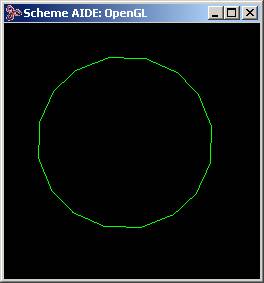
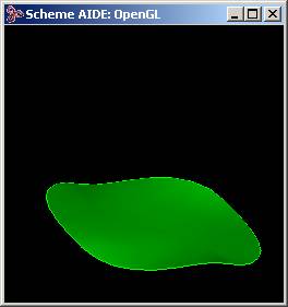
Figure. Edge before and after Covering
G1 Boundary with Options
This following C++ example illustrates how to use an acovr_options object to change the continuity on the boundary edges from G0 (default) to G1. The continuity values for boundary edges are specified in an acovr_edge_constraint object. The default continuity is changed by creating a G1 constraint object and setting its value in the acovr_options object.
Note: The set_default_constraint method copies values into the acovr_options object; it does not create an alias to the acovr_edge_constraint that is passed in.
|
#include "ckoutcom.hxx" // check_outcome #include "acovrapi.hxx" // Advanced Covering interface class FACE; // ACIS ENTITY FACE // ACIS initialization code & includes go here outcome out(0); out = api_initialize_deformable_modeling(); check_outcome(out); FACE* my_face = NULL; // my_edge is a pointer to an EDGE contained in the circuit we wish to cover // create options for G1 boundary acovr_options my_options; // create options with default values acovr_edge_constraint my_constraint; // create default constraint my_constraint.set_continuity(acovr_G1); // override default constraint continuity // override default options; this COPIES values, does not alias my_options.set_default_constraint(my_constraint); // cover with options out = api_advanced_cover(my_face, my_edge, &my_options); check_outcome(out); // my_edge may now be invalid since boundary EDGEs // are usually replaced with TEDGEs because of gaps // Code to save, etc. to the body goes here out = api_terminate_deformable_modeling(); check_outcome(out); // ACIS terminate code goes here |
The following scheme example illustrates how to use an acovr_options object to change the continuity on the boundary edges from G0 (default) to G1.
|
(view:gl) ;; #[view 14223092] (part:clear) ;; #t (view:edges ON) ;; #[view 14223092] (view:shaded ON) ;; #[view 14223092] ; Define an edge (define e1 (edge:spline (list (position 4 -3 -1) (position 5 0 0)(position 4 3 1)(position 3 4 2) (position 0 5 3)(position -3 4 2)(position -4 3 1) (position -5 0 0)(position -4 -3 -1)(position -3 -4 -2) (position 0 -5 -3)(position 3 -4 -2) (position 4 -3 -1)) "periodic")) ;; e1 ; The edge must belong to a body (define wi (wire-body (list e1))) ;; wi ; Sweep the non-planar edge (sweep:law wi (gvector 0.92832 -3.082417 9.467677) (sweep:options "solid" #f )) ;; #[entity 2 1] (iso) ;; #[view 14223092] (zoom-all) ;; #[view 14223092] ; Pick an edge to cover (ray:queue 10.2362 -22.4747 23.5337 -0.40824 0.81649 -0.408248 1) ;; #[ray (10.2362 -22.4747 23.5337)(-0.408244 0.816497 -0.408252)] (define e (pick-edge)) ;; e ; Create options object for G1 cover (define opt (adv-cover:options "default_continuity" 1)) ;; opt ; Cover the circuit (adv-cover:cover-circuit e opt) ;; #[entity 4 1] |
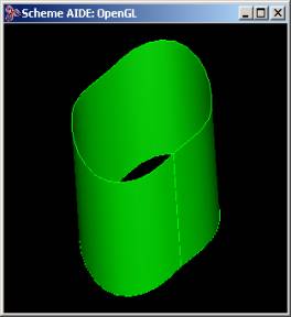
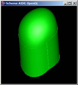
Figure. Edge before Sweeping, after Sweeping, and after Covering
G1 Boundary Re-Cover with Options
The following C++ example illustrates how to re-cover an existing face, using an acovr_options object to change the continuity on the boundary edges from G0 (default) to G1. The continuity values for boundary edges are specified in an acovr_edge_constraint object. The default continuity is changed by creating a G1 constraint object and setting its value in the acovr_options object. Note that the current shape of the face has no effect on the shape obtained by re-covering, unless the initial_face parameter is set in the acovr_options object.
Note: The set_default_constraint method copies values into the acovr_options object; it does not create an alias to the acovr_edge_constraint that is passed in.
|
#include "ckoutcom.hxx" // check_outcome #include "acovrapi.hxx" // Advanced Covering interface class FACE; // ACIS ENTITY FACE // ACIS initialization code & includes go here outcome out(0); out = api_initialize_deformable_modeling(); check_outcome(out); // my_face is a pointer to the FACE that we wish to re-cover // create options for G1 boundary acovr_options my_options; // create options with default values acovr_edge_constraint my_constraint; // create default constraint my_constraint.set_continuity(acovr_G1); // override default constraint continuity // override default options; this COPIES values, does not alias my_options.set_default_constraint(my_constraint); // re-cover with options out = api_advanced_cover(my_face, &my_options); check_outcome(out); // Code to save, etc. to the body goes here out = api_terminate_deformable_modeling(); check_outcome(out); // ACIS terminate code goes here |
The following scheme example illustrates how to re-cover an existing face, using an acovr_options to change the continuity on the boundary edges from G0 (default) to G1.
Note: The current shape of the face has no effect on the shape obtained by re-covering, unless the initial_face parameter is set in the acovr_options object.
|
(view:gl) ;; #[view 14288628] (part:clear) ;; #t (view:shaded ON) ;; #[view 14288628] ; Create a cylinder (solid:cylinder (position 0 0 0)(position 0 0 10) 3 2) ;; #[entity 1 1] ; Set the view (view:set(position 399.33636 -65.766586 293.700134) (position -3.0972864 -0.8948134 4.1505) (gvector -0.588 -0.047 0.807)) ;; #[view 14288628] (view:set-size 20.8333333333333 20.8333333333333) ;; #[view 14288628] (render:rebuild) ;; () ; Pick an end face (ray:queue 397.573 -65.7655 296.151 -0.80486 0.12974 -0.579099 1) ;; #[ray (397.573 -65.7655 296.151) (-0.804865 0.129741 -0.579103)] (define f (pick-face)) ;; f ; Set up options for G1 cover (define opt (adv-cover:options "default_continuity" 1)) ;; opt ; Re-cover the face of the cylinder (adv-cover:recover-face f opt) ;; #[entity 2 1] (render:rebuild) ;; () |
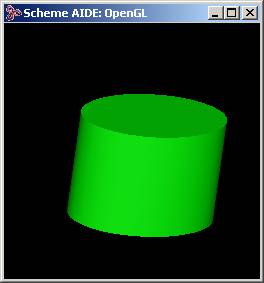
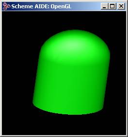
Figure. Cylinder before and after Re-Cover
G1 Snapping
The following C++ example illustrates how to snap an existing face to be G1 continuous with its neighbors. This is done by re-covering the face with G1 continuity constraints on the boundaries, and the initial_face parameter in the acovr_options set to itself. The Advanced Covering algorithm will impose G1 continuity on the boundaries, while attempting to maintain the shape of the (initial) face.
Note: The set_default_constraint method copies values into the acovr_options object; it does not create an alias to the acovr_edge_constraint that is passed in.
|
#include "ckoutcom.hxx" // check_outcome #include "acovrapi.hxx" // Advanced Covering interface class FACE; // ACIS ENTITY FACE // ACIS initialization code & includes go here outcome out(0); out = api_initialize_deformable_modeling(); check_outcome(out); // my_face is a pointer to the FACE that we wish to re-cover // create options for G1 boundary acovr_options my_options; // create options with default values acovr_edge_constraint my_constraint; // create default constraint my_constraint.set_continuity(acovr_G1); // override default constraint continuity // override default options; this COPIES values, does not alias my_options.set_default_constraint(my_constraint); // use my_face as initial_face so that the interior shape is maintained my_options.set_initial_face(my_face); // for a face that is already near-tangent, use small flattening // for large (60-90 degree) rotations use medium flattening (.4) // for extreme (>90 degree) rotations use large flattening (.7) // Tuning flattening will change the resulting shape my_options.set_flattening(.1); // assume face was near-tangent // re-cover with options out = api_advanced_cover(my_face, &my_options); // replaces geometry of my_face check_outcome(out); // Code to save, etc. to the body goes here out = api_terminate_deformable_modeling(); check_outcome(out); // ACIS terminate code goes here |
G1 Boundary with Symmetry Axis
The following C++ example illustrates how to use an acovr_options object to change the initial projection plane. The normal vector for the initial plane is specified in an acovr_options object. In this example, we dome the end-cap of a sliced cylinder.
Note: The set_default_constraint and set_plane_normal methods copy values into the acovr_options object; they do not create aliases to the acovr_edge_constraint and SPAunit_vector objects that are passed in.
|
#include "ckoutcom.hxx" // check_outcome #include "acovrapi.hxx" // Advanced Covering interface class FACE; // ACIS ENTITY FACE // ACIS initialization code & includes go here outcome out(0); out = api_initialize_deformable_modeling(); check_outcome(out); FACE* my_face = NULL; // Initial model is a cylinder around z-axis, which has been sliced at an // angle // my_face is a pointer to the (elliptical) face created by the slice // create options for G1 boundary acovr_options my_options; // create options with default values acovr_edge_constraint my_constraint; // create default constraint my_constraint.set_continuity(acovr_G1); // override default constraint continuity // override default options; this COPIES values, does not alias my_options.set_default_constraint(my_constraint); // create unit vector in z direction SPAunit_vector zdir(0., 0., 1.); // and use it to specify initial projection plane (COPIES, does not alias) my_options.set_plane_normal(zdir); // use medium flattening since this is large (90 degree) change my_options.set_flattening(.4); // re-cover with options out = api_advanced_cover(my_face, &my_options); check_outcome(out); // my_edge may now be invalid since boundary EDGEs are usually replaced with // TEDGEs because of gaps // Code to save, etc. to the body goes here out = api_terminate_deformable_modeling(); check_outcome(out); // ACIS terminate code goes here |
G0 Boundary with Guide Points
The following C++ example illustrates covering with guide points. Guide geometry is specified by passing EDGE (curve) or VERTEX (point) pointers to the acovr_options object. Any guide edges passed in must be contained in an ACIS body. Guide geometry can be specified singly (using the set_guide method), or in an ENTITY_LIST (using set_guides).
|
#include "ckoutcom.hxx" // check_outcome #include "lists.hxx" // class ENTITY_LIST; #include "acovrapi.hxx" // Advanced Covering interface class FACE; // ACIS ENTITY FACE // ACIS initialization code & includes go here outcome out(0); out = api_initialize_deformable_modeling(); check_outcome(out); FACE* my_face = NULL; // my_edge is a pointer to an EDGE contained in the circuit we wish to cover // create options for guide points // my_guides is an ENTITY_LIST containing VERTEXes // my_tol is a double, which overrides the default gap tolerance between the // covering surface and the vertex, if desired acovr_options my_options; // create options with default values my_options.set_guides (my_guides); // cover with options out = api_advanced_cover(my_face, my_edge, &my_options); check_outcome(out); // my_edge may now be invalid since // boundary EDGEs are usually replaced with TEDGEs because of gaps // Code to save, etc. to the body goes here out = api_terminate_deformable_modeling(); check_outcome(out); // ACIS terminate code goes here |
The following scheme example illustrates covering with guide points. Guide geometry is specified by passing EDGE (curve) or VERTEX (point) pointers to the acovr_options object. Any guide edges passed in must be contained in an ACIS body.
|
(view:gl) ;; #[view 15075060] (part:clear) ;; #t (view:edges ON) ;; #[view 15075060] (view:shaded ON) ;; #[view 15075060] ; Define an edge (define e1 (edge:spline (list (position 4 -3 -1) (position 5 0 0)(position 4 3 1)(position 3 4 2) (position 0 5 3)(position -3 4 2)(position -4 3 1) (position -5 0 0)(position -4 -3 -1)(position -3 -4 -2) (position 0 -5 -3)(position 3 -4 -2) (position 4 -3 -1)) "periodic")) ;; e1 ; The edge must belong to a body before covering (define wi (wire-body (list e1))) ;; wi ; Set the view (view:set(position 0.39907 0.88297 50.0561) (position 0.395055 -0.39471 3.357236) (gvector 0.006 0.999 -0.027)) ;; #[view 15075060] (view:set-size 14.533997417949 14.533997417949) ;; #[view 15075060] (render:rebuild) ;; () (define e (list-ref (entity:edges wi) 0)) ;; e ; Define a guide point (define v (vertex:from-position (position 0 0 5))) ;; v (define opt (adv-cover:options "guides" (list v))) ;; opt ; Cover the circuit (define f (adv-cover:cover-circuit e opt)) ;; f ; Remove the guide (entity:delete v) ;; () |

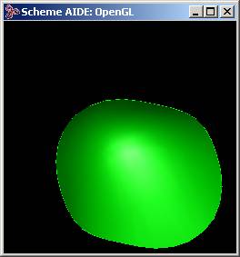
Figure. Edge before and after Covering
Mixed Continuity Boundary
The following C++ example illustrates covering with a mixed G0-G1 boundary. Users may want to set different continuities on different edges in a circuit. For example, blending a single edge of a cube and then removing the blend results in a circuit that should be covered with a G0 constraint on two of the edges and a G1 constraint on the other two edges. This is achieved by overriding the default constraint for specific edges using the set_boundary_constraint(s) method of acovr_options. The continuity level can simply be set to either acovr_G0 or acovr_G1 using the enumerated type acovr_continuity_level.
|
#include "ckoutcom.hxx" // check_outcome #include "acovrapi.hxx" // Advanced Covering interface class FACE; // ACIS ENTITY FACE // ACIS initialization code & includes go here outcome out(0); out = api_initialize_deformable_modeling(); check_outcome(out); FACE* my_face = NULL; // my_edge is a pointer to an EDGE contained in the circuit we wish to cover // create options for mixed G0-G1 boundary // my_G0_edge will have a G0 boundary, all others in my_circuit will have a // G1 boundary acovr_options my_options; // create options with default values acovr_edge_constraint my_constraint; // create default constraint my_constraint.set_continuity(acovr_G1); // override default constraint continuity my_options.set_default_constraint(my_constraint); // override default options // create G0 constraint object to override G1 default acovr_edge_constraint G0_constraint; // create constraint object G0_constraint.set_continuity(acovr_G0); // set continuity to G0 // override default constraint continuity for only my_G0_edge my_options.set_boundary_constraint(my_G0_edge,G0_constraint); // cover with options out = api_advanced_acover(my_face, my_edge, &my_options); check_outcome(out); // my_edge may now be invalid since // boundary EDGEs are usually replaced with TEDGEs because of gaps // my_face points to the new covering FACE. // my_face has been stitched to the BODY on which the circuit lies. // Code to save, etc. to the body goes here out = api_terminate_deformable_modeling(); check_outcome(out); // ACIS terminate code goes here |
The following scheme example illustrates covering with a mixed G0-G1 boundary. Users may want to set different continuities on different edges in a circuit. For example, blending a single edge of a cube and then removing the blend results in a circuit that should be covered with a G0 constraint on two of the edges and a G1 constraint on the other two edges. This is achieved by overriding the default constraint for specific edges.
|
(view:gl) ;; #[view 15140596] (part:clear) ;; #t (view:edges ON) ;; #[view 15140596] (view:shaded ON) ;; #[view 15140596] (define my_block (solid:block (position -10 -10 0) (position 10 10 20))) ;; my_block ; Set the view (view:set(position 13.34 -45.795 29.444) (position -1.9794 7.3928 9.6666)(gvector -0.148 -0.129 0.980)) ;; #[view 15140596] (view:set-size 32.9 32.9) ;; #[view 15140596] (view:refresh) ;; #[view 15140596] ; Pick the edges, create the blend (ray:queue 223.49 -479.02 421.626 -0.344055 0.712921 -0.61104 1) ;; #[ray (223.49 -479.02 421.626) (-0.344055 0.712921 -0.61104)] (define e1 (pick-edge)) ;; e1 (blend:var-rad-on-edge e1 2 6) ;; #[entity 3 1] (ray:queue 237.18 -470.61 423.73 -0.344055 0.712921 -0.61104 1) ;; #[ray (237.18 -470.61 423.73) (-0.344055 0.712921 -0.61104)] (define e2 (pick-edge)) ;; e2 (blend:var-rad-on-edge e2 6 2) ;; #[entity 4 1] (ray:queue 236.634 -479.605 413.543 -0.34405 0.71292 -0.61104 1) ;; #[ray (236.634 -479.605 413.543) (-0.344051 0.712922 -0.611041)] (define e3 (pick-edge)) ;; e3 (blend:round e3 6 "single") ;; (#[entity 5 1]) (ray:queue 234.572 -475.743 419.209 -0.344055 0.71292 -0.611 1) ;; #[ray (234.572 -475.743 419.209) (-0.344064 0.712938 -0.611015)] (define v1 (pick-vertex)) ;; v1 (blend:on-vertex v1) ;; #[entity 6 1] (blend:fix e1 ) ;; #t (zoom-all) ;; #[view 58853264] ; Remove a blend face (ray:queue 73.3375 -352.448 238.689 -0.17897 0.82865 -0.530376 1) ;; #[ray (73.3375 -352.448 238.689) (-0.178971 0.828654 -0.530379)] (define f1 (pick-face)) ;; f1 (face:remove f1) ;; #[entity 2 1] ; Pick circuit edge to cover (ray:queue -199.046 -361.12 122.644 0.4584 0.852 -0.251 0.6648) ;; #[ray (-199.046 -361.12 122.644) (0.458621 0.852411 -0.251121)] (define e2 (pick-edge)) ;; e2 (entity:set-color e2 BLUE) ;; () ; Make covering options - blended boundaries C1, non-blended C0 (define opt (adv-cover:options "default_continuity" 1 "circuit_edge_continuity" e2 0 )) ;; opt ; Cover the circuit (adv-cover:cover-circuit e2 opt) ;; #[entity 9 1] |
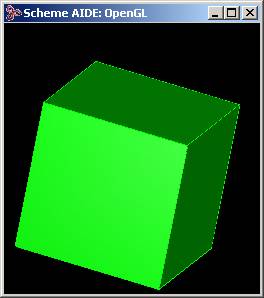

Figure. Solid before and after Blending
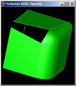
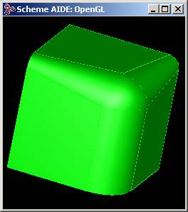
Figure. Edge before and after Covering
Specifying Default Tolerance
The following C++ example illustrates specifying a default G0 tolerance, that is, the tolerance used if not specified per edge. This is achieved by setting the acovr_options default_constraint. The default G1 tolerance is similar.
|
#include "ckoutcom.hxx" // check_outcome #include "acovrapi.hxx" // Advanced Covering interface class FACE; // ACIS ENTITY FACE // ACIS initialization code & includes go here outcome out(0); out = api_initialize_deformable_modeling(); check_outcome(out); FACE* my_face = NULL; // my_edge is a pointer to an EDGE contained in the circuit we wish to cover // create options for user-specified G0 tolerance // my_G0_tol is a double, the G0 tolerance we wish to specify acovr_options my_options; // create options with default values acovr_edge_constraint my_constraint = my_options.get_default_constraint() // get default constraint my_constraint.set_pos_tol(my_G0_tol); // override constraint default G0 tolerance my_options.set_default_constraint(my_constraint); // reset options default constraint // cover with options out = api_advanced_acover(my_face, my_edge, &my_options); check_outcome(out); // my_edge may now be invalid since // boundary EDGEs are usually replaced with TEDGEs because of gaps // my_face points to the new covering FACE. // my_face has been stitched to the BODY on which the circuit lies. // Code to save, etc. to the body goes here out = api_terminate_deformable_modeling(); check_outcome(out); // ACIS terminate code goes here |
The following scheme example specifying a default G0 tolerance, that is, the tolerance used if not specified per edge. The default G1 tolerance is similar.
|
; Define the tolerance values (define G0_tol 1.e-4) ;; G0_tol (define G1_tol 5.e-3) ;; G1_tol (view:gl) ;; #[view 25167684] (part:clear) ;; #t (view:edges ON) ;; #[view 25167684] (view:shaded ON) ;; #[view 25167684] ; define an edge (define e1 (edge:spline (list (position 4 -3 -1) (position 5 0 0)(position 4 3 1)(position 3 4 2) (position 0 5 3)(position -3 4 2) (position -4 3 1) (position -5 0 0) (position -4 -3 -1)(position -3 -4 -2) (position 0 -5 -3)(position 3 -4 -2 )(position 4 -3 -1)) "periodic")) ;; e1 ; The edge must belong to a body before covering (define wi (wire-body (list e1))) ;; wi ; Set the view (view:set(position 0.399 0.882 50.1) (position 0.395 -0.395 3.36)(gvector 0.006 0.999 -0.027)) ;; #[view 25167684] (view:set-size 14.534 14.534) ;; #[view 25167684] (render:rebuild) ;; () (define e (list-ref (entity:edges wi) 0)) ;; e ; Define an options object with an user-specified tolerance ; actually only need to change G0_tol in this example (define opt (adv-cover:options "default_tolerance" G0_tol G1_tol)) ;; opt ; Cover the circuit (define f (adv-cover:cover-circuit e opt)) ;; f ; Check that the tolerance was met: print out the G0 gap (print (car (adv-cover:max-gap opt))) ;; 7.07716419842637e-005 |
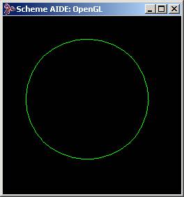
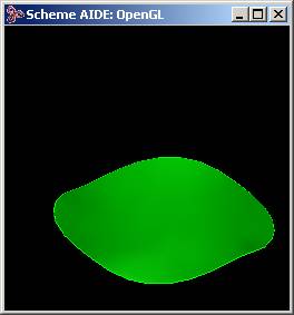
Figure. Edge before and after Covering
Mixed Boundary Tolerance
Users may want to set different tolerances on different edges in a circuit. The following C++ example illustrates covering with tolerance specified per boundary edge. This is achieved by changing the constraint tolerance for specific edges using the set_boundary_constraint(s) method of acovr_options. This example illustrates changing the G0 tolerance; the G1 tolerance is similar.
|
#include "ckoutcom.hxx" // check_outcome #include "acovrapi.hxx" // Advanced Covering interface class FACE; // ACIS ENTITY FACE // ACIS initialization code & includes go here outcome out(0); out = api_initialize_deformable_modeling(); check_outcome(out); FACE* my_face = NULL; // my_edge is a pointer to an EDGE contained in the circuit we wish to cover // create options for per-edge G0 tolerance // my_special_edge is a pointer to an EDGE that will have my_special_tol for G0 tolerance // my_special_tol is a double, the required G0 tolerance for my_special_edge acovr_options my_options; // create options with default values // get constraint object to change G0 tolerance acovr_edge_constraint my_constraint = my_options.get_boundary_constraint(my_special_edge); my_constraint.set_pos_tol(my_special_tol); // set G0 tolerance my_options.set_boundary_constraint(my_special_edge,my_constraint); // set constraint data for my_special_edge // cover with options out = api_advanced_acover(my_face, my_edge, &my_options); check_outcome(out); // my_edge may now be invalid since // boundary EDGEs are usually replaced with TEDGEs because of gaps // my_face points to the new covering FACE. // my_face has been stitched to the BODY on which the circuit lies. // Code to save, etc. to the body goes here out = api_terminate_deformable_modeling(); check_outcome(out); // ACIS terminate code goes here |
Covering Mixed Wire and Solid Edges
This example illustrates covering a circuit with edges coming from a mix of wires and solid bodies. The edges must form a closed circuit. The tolerance used to determine if two vertices are coincident while checking for circuit closure is the larger of the two position contraint tolerances on the corresponding edges.
The resulting face is independent of any existing topology - the user must stitch the new face into an existing body, as desired.
|
#include "ckoutcom.hxx" // check_outcome #include "lists.hxx" // class ENTITY_LIST #include "acovrapi.hxx" // Advanced Covering interface class FACE; // ACIS ENTITY FACE // ACIS initialization code & includes go here outcome out(0); out = api_initialize_deformable_modeling(); check_outcome(out); FACE* my_face = NULL; ENTITY_LIST my_circuit_edges; // Code to add all circuit edges to my_circuit_edges goes here // Edges can be added in any order acovr_options my_options; // create options with default values // Cover with options out = api_advanced_cover_no_stitch(my_face, my_edge, &my_options); check_outcome(out); // Code to stitch the new face into an existing body goes here, using api_stitch // Code to save, etc. to the body goes here out = api_terminate_deformable_modeling(); check_outcome(out); // ACIS terminate code goes here |
Using the Scheme command adv-cover:cover-edges, a FACE can be created by covering edges from a mix of wires and solids. Unlike the other Advanced Covering commands, adv-cover:cover-edges will not stitch the new face into an existing body - the user must stitch as desired. The edges to be covered must belong to a body, and must form a closed loop within a tolerance of SPAresabs.
|
(view:gl) ;; #[view 24971076] (part:clear) ;; #t (view:edges ON) ;; #[view 24971076] (view:shaded ON) ;; #[view 24971076] ; Set up the view (solid:block 0 0 0 10 20 30) ;; #[entity 1 1] (view:set(position 292.136 -370.757 141.673) (position 0.870 14.803 13.192)(gvector 0.809 0.579 -0.097)) ;; #[view 24971076] (view:set-size 40 40) ;; #[view 24971076] (view:refresh) ;; #[view 24971076] ; Remove a face (ray:queue 357.003 -12.452 355.45 -0.713 0.0414 -0.699 0.6648) ;; #[ray (357.003 -12.452 355.45) (-0.71347 0.0414273 -0.69946)] (define f (pick-face)) ;; f (entity:delete (face:unhook f)) ;; () ; Define an auxiliary edge to cover (ray:queue 364.98 -0.459 348.021 -0.713 0.0414 -0.6995 0.6648) ;; #[ray (364.98 -0.459 348.021) (-0.71322 0.0414128 -0.699716)] (define v1 (pick-vertex)) ;; v1 (ray:queue 349.407 -20.07 362.742 -0.713 0.0414 -0.6995 1.89) ;; #[ray (349.407 -20.07 362.742) (-0.71322 0.0414128 -0.699716)] (define v2 (pick-vertex)) ;; v2 (define e (edge:circular-3pt (vertex:position v1) (position 8 10 15)(vertex:position v2))) ;; e (define wi (wire-body (list e))) ;; wi ; Cover the first face (ray:queue 296.49 -331.463 -231.243 -0.564 0.665 0.488 1.89009) ;; #[ray (296.49 -331.463 -231.243) (-0.564433 0.665511 0.488375)] (define emid (pick-edge)) ;; emid (ray:queue 478.099 -87.6903 163.159 -0.939 0.1765 -0.294 1.89) ;; #[ray (478.099 -87.6903 163.159) (-0.939324 0.176561 -0.294102)] (define e1a (pick-edge)) ;; e1a (ray:queue 470.194 158.363 -113.338 -0.927 -0.295 0.229 1.89) ;; #[ray (470.194 158.363 -113.338) (-0.927559 -0.295178 0.229138)] (define e1b (pick-edge)) ;; e1b (define f1 (adv-cover:cover-edges (list emid e1a e1b))) ;; f1 (render:rebuild) ;; () ; Cover the second face (ray:queue 388.016 270.959 213.522 -0.765 -0.507 -0.395 1.89) ;; #[ray (388.016 270.959 213.522) (-0.765651 -0.507432 -0.395336)] (define e2a (pick-edge)) ;; e2a (ray:queue 387.492 262.674 225.155 -0.765 -0.507 -0.395 1.89) ;; #[ray (387.492 262.674 225.155) (-0.765651 -0.507432 -0.395336)] (define e2b (pick-edge)) ;; e2b (ray:queue 296.49 -331.463 -231.243 -0.564 0.665 0.488 1.89) ;; #[ray (296.49 -331.463 -231.243) (-0.564433 0.665511 0.488375)] (define emid (pick-edge)) ;; emid (define f2 (adv-cover:cover-edges (list e2a e2b emid))) ;; f2 (render:rebuild) ;; () ; Stitch it all together (define my-ent (entity:stitch (part:entities))) ;; my-ent ; Re-facet it (define r1 (refinement)) ;; r1 (refinement:set-prop r1 "grid mode" "AF_GRID_TO_EDGES") ;; () (refinement:set-prop r1 "min u_grid lines" 30) ;; () (refinement:set-prop r1 "min v_grid lines" 30) ;; () (entity:set-refinement my-ent r1) ;; (#[entity 15 1] #[entity 7 1]) (entity:facet my-ent) ;; 11384 (render:rebuild) ;; () |
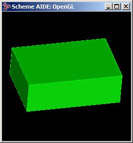

Figure. Solid Block before and after Removing a Face
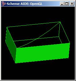
Figure. Auxillary Curve on the Block
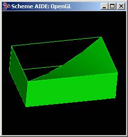

Figure. Solid Block after Covering the First Face, Second Face
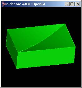
Figure. Solid Block after Stitching and Re-facetting
Specifying B-Spline Maximum Weight
The following C++ example illustrates using the max_spans parameter to change the maximum number of control points in the covering surface. Fewer control points can cause the covering surface to not meet gap tolerances, while surfaces with many control points suffer performance degradation. In this case, we will assume that the user would prefer a light-weight (fewer control points) surface, regardless of gap tolerances.
|
#include "ckoutcom.hxx" // check_outcome #include "acovrapi.hxx" // Advanced Covering interface #include <stdio.h> // printf class FACE; // ACIS ENTITY FACE // ACIS initialization code & includes go here outcome out(0); out = api_initialize_deformable_modeling(); check_outcome(out); FACE* my_face = NULL; // my_edge is a pointer to an EDGE contained in the circuit we wish to cover // create options object to specify num_spans acovr_options my_options; // create options with default values my_options.set_max_spans(10); // cover with options out = api_advanced_cover(my_face, my_edge, &my_options); check_outcome(out); // my_edge may now be invalid since // boundary EDGEs are usually replaced with TEDGEs because of gaps // my_face points to the new covering FACE // my_face has been stitched to the BODY on which the circuit lies // Code to save, etc. to the body goes here out = api_terminate_deformable_modeling(); check_outcome(out); // ACIS terminate code goes here |
Gap Reporting
The following C++ example illustrates gap reporting to check how well the boundary constraints were satisfied. The report_max_gap method of the acovr_options object examines each boundary edge and calculates the maximum constrained gap of each type (position and tangent) among the edges. G0 constraints only report position gaps, while G1 constraints report both position and tangency gaps. The maximum gaps for position and tangency are stored in an acovr_gap_report object. This object can then be queried for the information.
|
#include "ckoutcom.hxx" // check_outcome #include "acovrapi.hxx" // Advanced Covering interface #include <stdio.h> // printf class FACE; // ACIS ENTITY FACE // ACIS initialization code & includes go here outcome out(0); out = api_initialize_deformable_modeling(); check_outcome(out); FACE* my_face = NULL; // my_edge is a pointer to an EDGE contained in the circuit we wish to cover // create options for G1 boundary acovr_options my_options; // create options with default values acovr_edge_constraint my_constraint; // create default constraint my_constraint.set_continuity(acovr_G1); // override default constraint continuity my_options.set_default_constraint(my_constraint); // override default options // cover with options out = api_advanced_cover(my_face, my_edge, &my_options); check_outcome(out); // check boundary gap compliance acovr_gap_report gr; my_options.report_max_gap(gr); // maximum position gap over all boundary edges printf("boundary position gap %f \n", gr.get_pos_gap()); // maximum tangent gap over G1-constrained edges only printf("boundary position gap %f \n", gr.get_tan_gap()); // my_edge may now be invalid since // boundary EDGEs are usually replaced with TEDGEs because of gaps // my_face points to the new covering FACE // my_face has been stitched to the BODY on which the circuit lies // Code to save, etc. to the body goes here out = api_terminate_deformable_modeling(); check_outcome(out); // ACIS terminate code goes here |
The following scheme example illustrates gap reporting to check how well the boundary constraints were satisfied. Gaps are reported as a pair, G0 gap (model units) and G1 gap (radians).
|
(view:gl) ;; #[view 25102148] (part:clear) ;; #t (view:edges ON) ;; #[view 25102148] (view:shaded ON) ;; #[view 25102148] ; Define an edge (define e1 (edge:spline (list (position 4 -3 -1) (position 5 0 0)(position 4 3 1)(position 3 4 2) (position 0 5 3)(position -3 4 2)(position -4 3 1) (position -5 0 0)(position -4 -3 -1)(position -3 -4 -2) (position 0 -5 -3)(position 3 -4 -2 )(position 4 -3 -1)) "periodic")) ;; e1 ; The edge must belong to a body (define wi (wire-body (list e1))) ;; wi ; Sweep the non-planar edge (sweep:law wi (gvector 0.9283 -3.0824 9.4676) (sweep:options "solid" #f )) ;; #[entity 2 1] (iso) ;; #[view 25102148] (zoom-all) ;; #[view 25102148] ; Pick an edge to cover (ray:queue 10.2362 -22.4747 23.5337 -0.40824 0.81649 -0.40825 1) ;; #[ray (10.2362 -22.4747 23.5337) (-0.408243 0.816497 -0.408253)] (define e (pick-edge)) ;; e ; Create options object for G1 cover (define opt (adv-cover:options "default_continuity" 1)) ;; opt ; Cover the circuit (adv-cover:cover-circuit e opt) ;; #[entity 4 1] ; Report the gaps found during covering (print (adv-cover:max-gap opt)) ;; (0.000545652599057301 0.00641567744673524) |
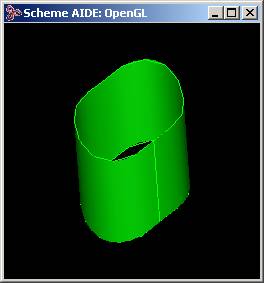
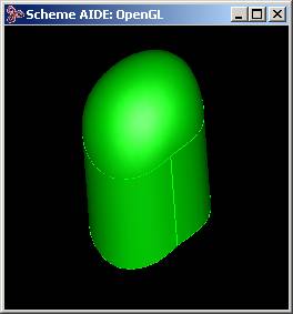
Figure. Edge before and after Covering
Conflict Reporting
Boundary constraints can conflict, which may preclude meeting tolerances. This can only happen when circuit edges are discontinuous, and a G1 boundary condition is enforced. For more details, refer to the Technical Overview. The following C++ example illustrates how to retrieve conflict report information from the advanced covering options object.
|
#include "ckoutcom.hxx" // check_outcome #include "acovrapi.hxx" // Advanced Covering interface class FACE; // ACIS ENTITY FACE class EDGE; // ACIS initialization code & includes go here outcome out(0); out = api_initialize_deformable_modeling(); check_outcome(out); FACE* my_face = NULL; int nCon = 0; // store number of conflicts int* conTypes = NULL; // store conflict types ENTITY_LIST conEdges0, conEdges1; // store conflicting edge pairs // my_edge is a pointer to an EDGE contained in the circuit we wish to cover // create options for G1 boundary acovr_options my_options; // create options with default values // cover with options out = api_advanced_cover(my_face, my_edge, &my_options); check_outcome(out); // my_edge may now be invalid since boundary EDGEs // are usually replaced with TEDGEs because of gaps // Query my_options for conflict data, store conflicts nCon = my_options.get_num_conflicts(); if (nCon>0) { conTypes = ACIS_NEW int[nCon]; for (int ii=0; ii < nCon; ii++) { int iType = 0; EDGE* e0=NULL; EDGE* e1=NULL; my_options.get_conflict(e0,e1,iType); conEdges0.add((ENTITY*)e0); conEdges1.add((ENTITY*)e1); conType[ii] = iType; } } // Code to save, etc. to the body goes here out = api_terminate_deformable_modeling(); check_outcome(out); // ACIS terminate code goes here |
Boundary constraints can conflict, which may preclude meeting tolerances. This can only happen when circuit edges are discontinuous, and a G1 boundary condition is enforced. For more details, refer to the Technical Overview.
|
(view:gl) ;; #[view 33621056] (part:clear) ;; #t (view:edges ON) ;; #[view 33621056] (view:shaded ON) ;; #[view 33621056] (view:set(position -302.77 375.94 -130.35 ) (position 0 0 0)(gvector 0.108 -0.246 -0.963)) ;; #[view 33621056] (view:set-size 18.315 18.315) ;; #[view 33621056] (view:refresh) ;; #[view 33621056] ; Define edges forming a circuit ; edges have a G2 discontinuity at the vertices (define ec0 (edge:circular (position -3 0 0) 3 90 270)) ;; ec0 (define ec1 (edge:circular (position 3 0 0) 3 -90 90)) ;; ec1 (define etop (edge:linear (position -3 3 0) (position 3 3 0))) ;; etop (define ebot (edge:linear (position -3 -3 0) (position 3 -3 0))) ;; ebot (define wi (wire-body (list ec0 ec1 etop ebot))) ;; wi ; Sweep to make a solid (define axis (edge:linear (position 0 0 0) (position 0 0 3)))(sweep:law wi axis (sweep:options "draft_angle" 10)) ;; #[entity 5 1] ; Pick a face to recover (ray:queue 253.503 1031.56 -588.406 -0.2092 -0.8495 0.48429 1) ;; #[ray (253.503 1031.56 -588.406) (-0.209205 -0.849521 0.484302)] (define f (pick-face)) ;; f (define opt (adv-cover:options "default_continuity" 1)) ;; opt ; Re-cover and make G1 at boundary (adv-cover:recover-face f opt) ;; #[entity 7 1] (render:rebuild) ;; () ; The G2 edge discontinuity conflicts with ; the G1 boundary constraint (adv-cover:num-conflicts opt) ;; 4 ; returns 4, one for each vertex (adv-cover:get-conflict-type opt 0) ;; 2 ; returns 2 (define confl (adv-cover:get-conflicting-edges opt 0)) ;; conf1 ; Display the conflicting edges in BLUE (entity:set-color (list-ref confl 0) BLUE) ;; () (entity:set-color (list-ref confl 1) BLUE) ;; () |
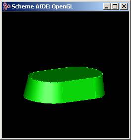
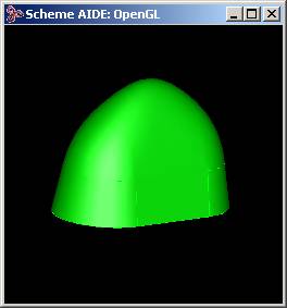
Figure. Solid before and after Covering
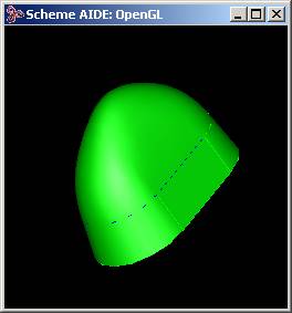
Figure. Solid with Conflicting Edges (highlighted in blue)
[Top]
© 1989-2007 Spatial Corp., a Dassault Systèmes company. All rights reserved.