Advanced Covering
Advanced Covering Interface
C++ Interface
The Advanced Covering C++ interface includes several functions and three classes. The classes include: acovr_options, acovr_edge_constraint, and acovr_gap_report. The functions include: api_advanced_cover (both overloaded APIs) and api_advanced_cover_no_stitch. The acovr_options object is used to define optional parameters that configure the covering problem.
The functions and classes are illustrated in Advanced Covering C++ Examples. Refer to the function and class reference templates for more information.
Scheme Interface
A Scheme interface is also supplied for learning and testing Advanced Covering in a Scheme environment, such as using Scheme AIDE. Refer to the Scheme extension reference templates for more information.
Some Advanced Covering Terminology
This section explains some terms that are used in discussions of Advanced Covering.
Circuit
A circuit is a collection of edges that form a closed loop. For Advanced Covering, the loop must not be self-intersecting. The circuit edges can either lie on a collection of surfaces, or a collection of wires, but not some of each. Each edge in the circuit must be a wire or a sheet boundary; i.e., it must have only one coedge. Given an edge in an unambiguous (that is, 2 and only 2 valid circuit edges at every vertex) circuit, api_adv_cover will automatically find the circuit to be covered. Advanced Covering of ambiguous circuits can be done by calling api_advanced_cover_no_stitch on the edges in the circuit.
Gn Boundaries
The notation Gn refers to smoothness while crossing a boundary. The larger the value of n, the greater the smoothness. A G0 boundary has position smoothness; that is, there are no jumps in position. A G1 boundary has tangent smoothness; that is, there are no jumps in tangency. Visually, tangency is slope; mathematically, it is the xyz first derivative.
For a surface, a boundary is (usually) a set of curves. For a curve, a boundary is always a set of points.
The junction between two boundary curves in a circuit must be at least G0 continuous; that is, contain no position jumps.
For example, removing the top face from a cube gives an obvious circuit of 4 edges that has G0 continuity between the boundary curves. Removing the top face from a blended cube gives a circuit of eight edges that has G1 continuity between the boundary curves; that is, no tangency (slope) jumps at curve joints. In this case, the boundary curves will not be G2 - there will be jumps in the curvature at curve joints.
Guide Points and Guide Curves
Guide points and guide curves are constraints that are not part of the covering boundary; that is, they are not part of the final model topology. Guide constraints can only constrain position (they are G0 constraints).
Position and Tangency Gaps
Gaps are jumps at a boundary. Position (abbreviated as "pos") gaps are jumps in the xyz coordinates. Tangency (abbreviated as "tan") are gaps in the slope, or xyz derivatives.
Tolerance
Tolerance is the user-specified allowable gap at a boundary. As with gaps, there are separate tolerances for position and tangency. Tolerances may be dictated by machining or other downstream processes.
Conflict (constraint)
Boundary constraints can conflict, which may preclude meeting tolerances. For example, if two adjacent boundary constraints have different tangents at their junction, the resulting surface normal must be orthogonal to both, so it is uniquely determined. This may conflict with an additional tangency constraint.
Flattening
The flattening parameter is used to control how G1 constraints affect the shape of the covering surface. As an example, consider slicing off the top of a cone and then performing a G1 cover to make a smooth "nosecone". When the flattening parameter is zero, the cross-sectional shape of the "nosecone" will be roughly parabolic. When the flattening is large (.4 to .7) the cross-section will be flat in the center, with sharp "shoulders" near the outside to accommodate the tangency constraints.
Initial Projection Plane
The Advanced Covering algorithm begins with an Initial Projection Plane. The boundary to be covered is projected into this plane to determine which points in the covering surface should be associated with the corresponding boundary points. The initial plane also affects the shape induced by G1 constraints; G1 constraints tend to be satisfied by making the covering surface bulge in the direction of the normal to the initial plane. By overriding the choice of initial plane, users can adjust the shapes resulting from G1 covers. The initial projection plane can be replaced with an initial surface.
Initial Surface
Users can specify an initial surface shape instead of an initial projection plane. The Advanced Covering algorithm will deform this surface onto the boundary geometry, while attempting to maintain its gross shape. Specifying an initial surface is also useful for covering boundary circuits which are not plane projectable or which would result in a "double valued" covering surface (relative to the initial plane). Advanced Covering produces the best results when it starts from an initial surface which has roughly the same shape as the desired covering surface.
Basic Steps for Using Advanced Covering
The basic steps in using the Advanced Covering are:
- Find an edge in the circuit to be covered or a face to be re-covered.
- Create an options object (acovr_options), which overrides non-default values for constraint continuity, constraint tolerance, maximum number of B-spline spans, projection plane or surface, and flattening factor (G1 covers only).
- Use acovr_options methods to set any non-default values for constraint continuity, constraint tolerance, maximum number of B-spline spans, projection plane or surface, and flattening factor, as desired.
- Call api_advanced_cover with the appropriate signature.
General Advanced Covering Algorithm
The general algorithm used by Advanced Covering is:
- The user specifies a "plane projectable" boundary circuit.
- Advanced Covering calculates a "projection plane" that is used as a "first guess" for the shape of the covering surface. This choice of projection plane can be overridden through the acovr_options object.
- In addition, the projection plane can be replaced by an arbitrary spline surface, using the set_initial_face method. An initial spline surface is created from the projection plane or if specified, the geometry of the initial_face. Knots are added to the initial surface up to at most max_spans in each direction.
- Boundary and guide geometry is projected onto the initial surface, and the covering surface is deformed so that the projected points are "pulled onto" the boundary and guide geometry. The algorithm terminates when the tolerance is met, or when the user-specified maximum number of spans has been reached, or when boundary circuit constraint conflicts prevent further gap reduction. The covering surface is a B-spline, which will have at most the user-specified maximum number of spans.
- The covering surface is stitched back into the ACIS model. Any edges that have position gaps larger than SPAresabs are converted into tolerant edges.
- Edges which are sheet boundaries (that is, edges belonging to only one face) have their geometry changed to that of the covering face coedge. This changes both the edge and the vertex geometry, but ensures there is no gap between the edge and the face.
Guide and Circuit (Constraint) Layout
Covering works by deforming an initial covering face onto the user-input covering circuit and guides. Guide points and guide curves, and the covering circuit, must be laid out according to some rules governing their projection into the initial covering face. The default initial covering face is the best-fit plane of the covering circuit. In most cases, the plane of the covering circuit is obvious; see the following two figures. In the following, constraints refer collectively to guides and the covering circuit.
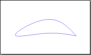
Figure. Covering Circuit
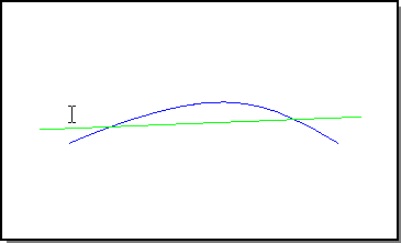
Figure. Circuit (Blue) and Plane in Cross-section
Rule 1. Projected constraints must not intersect.
Guides should not project onto each other or onto the covering circuit, in the initial face. See the following figures for an example of a guide point projecting onto the covering circuit. Such an arrangement requests the covering surface be in two places at the same time, that is, presents conflicting constraints. If a guide is placed so it nearly projects into the circuit boundary, placing an auxiliary guide which projects near the circuit center helps make the covering surface better reflect the design intent.
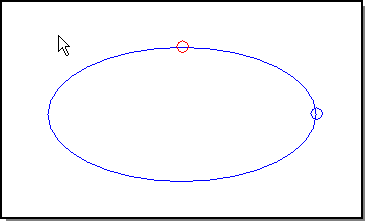
Figure. View in the Initial Covering Face (Plane)
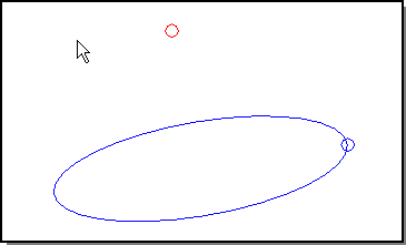
Figure. Circuit (Blue), Guide Point (Red)
Rule 2. Projected constraints must have consistent containment.
Ordering constraints by z-depth, with respect to the initial face, guide curves and the covering circuit should not produce mid-cover bulges. See the following figure, which shows the default case of an initial planar face.
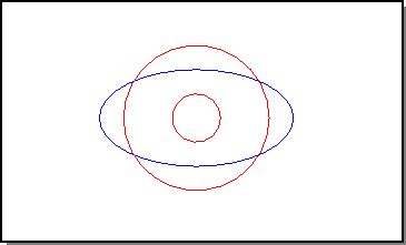
Figure. View in Initial Plane: Circuit (Blue), Guides (Red)
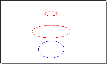
Figure. Perspective View: Covering Surface Would Bulge at Middle Guide
Rule 3. Projected constraints must not cross the initial face boundaries.
This rule only applies to a user-specified initial face. The default initial face, in the plane of the covering circuit, or a user-specified initial plane automatically has appropriate boundaries calculated. See the following figure for an example.
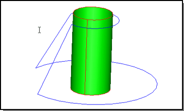
Figure. Illegal Constraints: Projected Circuit (Blue) Crosses Initial Face Boundary (Red) on Cylinder Seam
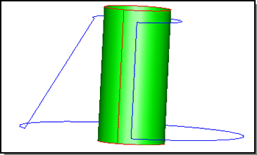
Figure. Legal Constraints: Projected Circuit Does Not Cross Initial Face Boundaries
Advanced Covering Limitations
This section lists some of the Advanced Covering limitations.
Circuits
- Covering circuits must be projectable onto the initial surface.
- Each edge in the circuit must have a single coedge.
- A circuit is not allowed to branch.
- A circuit is not allowed to be self-intersecting.
- "Double-valued" covering surfaces cannot be created, that is, no two points on the covered surface can project to the same point on the initial surface. For example, in the following figure, some points on the top of the surface, project to the same points on the plane as points on the folded under "flaps" (a few sample points are highlighted). Another example of such an illegal circuit is the seam of a baseball - the "lobes" are folded under the top, requiring a double-valued covering surface. However, if a sphere were used as the initial surface in this case, the double-valued covering could be avoided.
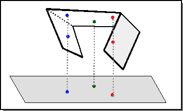
Figure. Illegal Double-Valued Covering Surface
The following figure illustrates a single-valued covering surface. The side "flaps" flare outward, so no two points on the covering surface project to the same point on the plane.
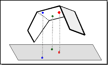
Figure. Legal Single-Valued Covering Surface
A circuit used to specify a cover must not force the surface to be discontinuous. For example, performing a G1 cover of the circuit formed by removing the top face from a cube would force the covering surface to have a tangent discontinuity at the corners, so this operation is not allowed.
This limitation does not apply if the discontinuities are coplanar with the adjacent surface. For example, performing a G1 cover of a star shape (with many sharp corners) cut out of the center of an existing (smooth) surface is allowed, because the discontinuities are compatible with the smooth covering surface.
Negative, Zero, or Near-Zero Draft Angle
Negative, zero, or near-zero draft angle bodies can be covered with a G0 boundary, but G1 boundary constraints may require tuning of the flattening parameter and/or initial plane. An example of this is the G1 cover of the top of a cylinder; the flattening parameter specifies how high the resulting "dome" will be. In general, specifying G1 boundary constraints which will result in a significantly different surface than the corresponding G0 cover can result in unaesthetic shapes.
Boundary Constraints G0 or G1 Only
Boundary constraints can enforce at most G1 continuity with adjacent surfaces - no higher continuity is allowed.
Guide Constraints G0 Only
Guide constraints can only specify G0 continuity. In contrast, boundary constraints may specify G1 continuity.
Mixing Wire and Solid Edges
Boundary constraints come from circuits. Circuits are made up of edges from solid or wire bodies. The API, api_advanced_cover requires that within a single covering specification, all circuit edges must come from either a solid or wire body, but not a mix of both.
The API, api_advanced_cover_no_stitch can take a mix of edges from solid or wire bodies; the resulting circuit must be closed. As of R13SP6, the tolerance used to determine if two vertices are coincident while checking for circuit closure is the larger of the two position contraint tolerances on the corresponding edges. Prior to R13SP6, the tolerance is resabs.
Surface Checking
As of R13 SP2, Advanced Covering checks the proposed covering surface for errors
(for example, self-intersection, and high curvature). If it cannot find an
error-free surface, the API call fails with the message:
"Covering would produce surface with errors - check for conflicting constraints
or try looser tolerances"
These surface errors usually occur when the shape of the final covering surface is very different from the initial surface's shape. This is usually due to tangent constraints causing a large change in the surface normal in some region of the surface (that is, the final surface is strongly "bent" relative to the initial surface, as in doming). When this situation occurs, a good covering surface can often be obtained by relaxing the required constraint tolerances (either position or tangent) being passed into Advanced Covering and retrying the cover. The constraints being passed into Advanced Covering should also be examined in such cases for conflicts.
This advice also holds true for successful covering surfaces that have undesired "bumps". By relaxing tolerances, adjusting the flattening parameter, and/or removing constraints, a smoother covering surface can often be obtained.
Note: The Advanced Covering API has internal logic that attempts to use a looser fitting surface on its own, which can result in it returning surfaces which have fewer than the maximum number of splits and still does not satisfy all of the constraints. If the covering surface which best satisfies the constraints has errors, it will check alternate surfaces which are close to satisfying the constraints for one which checks and use that one as the covering surface. Only if this procedure fails will the "surface with errors" message be returned. By loosening tolerances on some of the constraints the user can both expand the set of nearby surfaces which will be checked and change the interaction between the constraints (which will result in different surface shapes that might be error-free).
Note: This final check of the surface can be turned off by calling the set_final_surf_check() method of the acovr_options object. Turning off the final surface check is not recommended, because it can result in surfaces with errors which will cause downstream operations to fail. The capability to turn off the final surface check is intended as a diagnostic tool so that customers can visualize the proposed surface that Advanced Covering attempted to make. Also note that turning off the final check also turns off the exploration of alternate surfaces discussed above. This means that turning off the final check can cause Advanced Covering to produce surfaces with errors in cases where the same call with the final check on would produce an error-free surface.
Related topics:
Advanced Covering C++ Examples
[Top]
© 1989-2007 Spatial Corp., a Dassault Systèmes company. All rights reserved.