Scheme Extensions ds:j* thru Zz |
|
|
|
Technical Article |
| Scheme is a public domain programming language, based on the LISP language,
that uses an interpreter to run commands. ACIS provides extensions (written
in C++) to the native Scheme language that can be used by an application
to interact with ACIS through its Scheme Interpreter. The C++ source files
for ACIS Scheme extensions are provided with the product. Spatial's Scheme
based demonstration application, Scheme ACIS Interface Driver Extension
(Scheme AIDE), also uses these Scheme extensions and the Scheme Interpreter.
|
ds:journal-off
- Action
-
Closes the journal file and turns off API level journaling.
Filename-
scm/scmext/ds/dsscm.cpp
APIs-
api_dm_journal_off
Syntax-
(ds:journal-off)
Arg types-
Returns-
unspecified
Description
Closes any file opened by the ds:journal-on call and turns off API level
journaling.
; ds:journal-off
; Turn journaling off with cascade.
(ds:journal-on "deform.jou" 1)
;; ()
; Close the journal file.
(ds:journal-off)
;; () |
[Top]
ds:journal-on
- Action
-
Turns on journaling of internal API function calls. This is a debugging
tool.
Filename-
scm/scmext/ds/dsscm.cpp
APIs-
api_dm_journal_on
Syntax-
(ds:journal-on filename [cascade=0])
Arg types-
Returns-
unspecified
Description
Opens the file "filename" for write and turns on API level function
call journaling. This will cause each API call to log its argument values
on entry and exit from the subroutines. This capability is supported as
a debugging tool only and is not meant to act as a session history tool.
Existing data in file "filename" is overwritten.
- The value of cascade controls the amount of information written
into the journal file. The values for cascade are:
-
0 = only journal API entry calls are logged
-
1 = all calls within the API are logged
-
2 = journal entry and intersection callbacks are logged
-
3 = journal entry, cascading DM calls, and intersect callbacks
- Arguments
-
filename to write and to turn on API level function call journaling.
-
cascade controls the amount of information written into the journal
file.
; ds:journal-on
; Turn journaling on with cascade.
(ds:journal-on "deform.jou" 1)
;; ()
; Close the journal file.
(ds:journal-off)
;; ()
; ds:journal-off:
; syntax: (ds:journal-off)
; effect: turn off API level journaling |
[Top]
ds:link-face
- Action
-
Adds a face to a multi-surface deformation mesh.
Filename-
scm/scmext/ds/dsscm.cpp
APIs-
api_dm_add_multi_face,
api_dm_get_attrib_dm2acis
Syntax-
(ds:link-face face1 face2 [adm-options]
[acis-opts])
Arg types-
Returns-
integer
Description
Adds a second face, face2, to the multi-surface deformation mesh associated
with the first face, face1, so both faces can deform as one. For every
boundary of face2 that connects to another face in the multi-surface mesh,
this extension adds a link constraint. For every boundary of face2 that
connects to a face not in the multi-surface mesh, this extension adds
a curve constraint of type ds_solid_cstrn, and for every boundary of face2
not connected to another face this extension adds a curve constraint of
type ds_bound_cstrn.
The adm-options and acis-opts allow the use of legacy algorithms in
subsequent adm operations. adm-options are created with ds:adm-options
and acis-opts are created with acisoptions:set.
See ds:adm-start for another example of option usage.
The link constraints default to C0 constraints when face1 and face2
boundaries initially are not tangent and default to C1 constraints when
face and owner boundaries are initially tangent.
Subsequent calls to ds:solve face1 or
ds:solve face2 deform the shapes
of face1 and face2.
If face2 is already a member of another deformable modeling hierarchy,
then all faces in both hierarchies are joined together to act as one.
When this happens all the tag numbers in face2's hierarchy are incremented
by an amount tag_shift to ensure that every tag number remains unique
throughout the entire hierarchy.
Returns a list of the tag number used for face2's associated deformable
model, and tag_shift. tag_shift is 0 in all cases except for the merging
of two existing deformable models.
- Arguments
-
face1 face to which face2 will be meshed.
-
face2 face which is going to be meshed.
-
adm-options allow the use of legacy algorithms in subsequent adm operations.
-
acis-opts contains journaling and versioning information.
; ds:link-face
; Create a block.
(define block (solid:block (position -15 -15 -15)
(position 15 15 15)))
;; block
; Pick 3 adjacent faces on block.
; Define the first face.
(define face1 (pick:face (ray (position 0 0 0)
(gvector 1 0 0)) ))
;; face1
; Define the second face.
(define face2 (pick:face (ray (position 0 0 0)
(gvector 0 1 0)) ))
;; face2
; Define the third face.
(define face3 (pick:face (ray (position 0 0 0)
(gvector 0 0 1)) ))
;; face3 ; Create deformable modeling hierarchy on first face
; by executing any old DM command.
(ds:get-tag-summary face1)
; tgt_dmod = 2, Deformable Surface
; parent = NULL
; sibling = NULL
; child = NULL
; id type
; --- ----
; 3 Curve Constraint
; 4 Curve Constraint
; 5 Curve Constraint
; 6 Curve Constraint
;; (2 12 -1 0 -1 0 -1 0 3 6 4 6 5 6 6 6)
; Link in (second) face that is not part of a DM
; hierarchy.
(ds:link-face face1 face2)
;; (11 9)
; 11 = face2's dmod tag
; 9 = tag shift for face2's tags
; Create separate DM hierarchy on third
face.
(ds:get-tag-summary face3)
; tgt_dmod = 2, Deformable Surface
; parent = NULL
; sibling = NULL
; child = NULL
; id type
; --- ----
; 3 Curve Constraint
; 4 Curve Constraint
; 5 Curve Constraint
; 6 Curve Constraint
;; (2 12 -1 0 -1 0 -1 0 3 6 4 6 5 6 6 6)
; Link two hierarchies together.
(ds:link-face face1 face3)
;; (19 17)
; 19 = face3's dmod tag
; 17 = tag shift for face3's tags
; Show tag shift in second hierarchy's (face3's)
; tags.
; NOTE: only way to get at face3's dmod in the mesh
; is to use face3's tag in "target" argument.
(ds:get-tag-summary face1 19)
; tgt_dmod = 19, Deformable Surface
; parent = NULL
; sibling = NULL
; child = NULL
; id type
; --- ----
; 6 Link load (multisurf)
; 15 Link load (multisurf)
; 22 Curve load
; 23 Curve load
;; (19 12 -1 0 -1 0 -1 0 6 18 15 18 22 6 23 6)
|
[Top]
ds:make-tracking-curve
- Action
-
Creates a deformable curve model, suitable for tracking curve constraints.
from a crv_cstrn or link_cstrn.
Filename-
scm/scmext/ds/dsscm.cpp
APIs-
api_dm_get_attrib_dm2acis
Syntax-
(ds:make-tracking-curve owner tag target=1)
Arg types-
Returns-
integer
Description
Returns the tag identifier of a newly constructed deformable curve model
which is linked to the shape of the input crv_cstrn or link_cstrn. Sculpting
the shape of the returned deformable model changes the shape of the constraint,
which in turn changes the shape of the constrained surface.
The basics of curve tracking include:
- Select a crv_cstrn or a link_cstrn from an existing
deformable model.
- Promote the constraint to a tracking curve constraint,
(ds:make-tracking-curve)
- Sculpt the tracking curve deformable model by adding
and modifying loads and constraints and then calling ds:solve.
- Change the shape of the constrained surface via ds:solve
and the constrained-surface-tag.
The input tag is expected to identify an existing curve or link constraint
within the deformable modeling hierarchy associated with the input entity
object.
When the input tag value identifies a link_cstrn, the target value is
used to select which side of the link is to be made into a tracking curve.
A 1 uses the side associated with the link's first deformable model, and
2 defines the side associated with the link's second deformable model.
- Arguments
-
owner ACIS face or edge on which the deformable model lives.
-
tag is to identify an existing curve or link constraint within the
deformable modeling hierarchy associated with the input entity object.
-
target value is used to select which side of the link is to be made
into a tracking curve.
Limitations-
Creates from crv_cstrn or link_cstrn only.
; ds:make-tracking-curve
; Track a straight crv-cstrn on a square test face and
use it.
; Build a test square spline face.
; (6x6 control points, x and y side length = 36)
(define dsmodel1 (ds:test-face 6 6 36
36 0))
;; dsmodel1
; Render the loads and constraints.
(ds:set-draw-state dsmodel1 2
(+
ds-draw-cstrns ds-draw-loads))
;; ()
; make an edge crv-cstrn into a tracking
curve constraint
; dsmodel2 will be the tag of the new
tracking curve deformable model (dmod)
(define dsmodel2 (ds:make-tracking-curve
dsmodel1 3))
;; 0
; Add point constraints at the tracking
curve dmod boundaries
(ds:add-pt-cstrn dsmodel1 dsmodel2 "position"
(par-pos
0.0 0.0))
;; 8
(ds:add-pt-cstrn dsmodel1 dsmodel2 "position"
(par-pos
1.0 1.0))
;; 9
; Add a pt-cstrn at the tracking curve
dmod center and track it
(define cc1 (ds:add-pt-cstrn dsmodel1
dsmodel2 "position"
(par-pos
0.5 0.5)))
;; cc1
(ds:set-pt-xyz dsmodel1 cc1 0 (position
18 0 20))
;; 8
; Compute a new tracking curve shape
(ds:solve dsmodel1 dsmodel2 1)
;; () |
[Top]
ds:pick-dmod-tag
- Action
-
Gets the tag identifier for a deformable model given a pick-event.
Filename-
scm/scmext/ds/dsscm.cpp
APIs- api_dm_get_attrib_dm2acis
Syntax-
(ds:pick-dmod-tag owner pick-event)
Arg types-
Returns-
(integer ...)
Description
This Scheme extension returns the tag of a deformable model object selected
by a pick-event.
When the pick-event identifies a deformable model in the patch hierarchy,
it is made the active deformable model.
The input pick-event is used to create a line which runs through the
pick-point in the viewing direction. The distances between this line and
all deformable models in the owner's deformable model hierarchy are computed.
When the minimum of these distances is less than the distance represented
by five pixels in the current view, the returned tag_id is set. Otherwise,
tag_id is set to -1.
- Arguments
-
owner ACIS face or edge on which the deformable model lives.
-
pick-event is used to create a line which runs through the pick-point
in the viewing direction.
Limitations-
Z-depth conflicts may give spurious results with child patches, depending
on orientation.
; ds:pick-dmod-tag
; build a sheet-body
(define my_sheet (sheet:face
(face:plane (position 0 -5 0) 10 10)))
;; my_sheet
; get the face
(define ds-model
(list-ref (entity:faces my_sheet) 0))
;; ds-model
; get a nice view
(iso)
;; #[view 852730]
(zoom-all)
;; #[view 852730]
; pick the dmod using the mouse
(ds:pick-dmod-tag ds-model (read-event))
;; -1 |
[Top]
ds:pick-par-pos
- Action
-
Gets the parametric position of a location on the owner deformable
model, selected by a pick-event ray.
Filename-
scm/scmext/ds/dsscm.cpp
APIs- api_dm_get_attrib_dm2acis
Syntax-
(ds:pick-par-pos owner pick-event [tag-flag=2])
Arg types-
Returns-
par-pos
Description
Returns the parametric position (par-pos) location of the first intersection
between the deformable surface and a ray starting at the pick-event point
moving in the viewing direction. When the pick ray does not intersect
the surface, unspecified is returned.
- The deformable model in the patch hierarchy containing the shape
intersected by the pick ray becomes the active deformable model (Refer
to the documentation for ds:get-active-patch).
The values for tag-flag
are:
-
2 all root siblings and offspring patches are checked
-
1 the search begins at the active deformable model
-
n where n is the tag value
of a particular deformable model, the search begins at that model within
the hierarchy
- Arguments
-
owner ACIS face or edge on which the deformable model lives.
-
pick-event is used to create a line which runs through the pick-point
in the viewing direction.
-
tag-flag has different values 2 for checking all root siblings and
offspring patches, 1 where the search begins at the active deformable
model, n is the tag value.
; ds:pick-par-pos
; Get the xyz position of a spring load.
; Build a test square spline face.
; (6x6 control points, x and y side length = 36)
(define dsmodel1 (ds:test-face 6 6 36 36 0))
;; dsmodel1
; Do not display entity / ds test face exists.
(define erase (entity:erase dsmodel1))
;; erase
; Render the loads and constraints.
(ds:set-draw-state dsmodel1 1
(+ ds-draw-cstrns ds-draw-loads))
;; ()
; Get a par-pos from a pick.
(ui:info-dialog "Pick a location on the face")
;; #t
; Pick a location on the face.
(ds:pick-par-pos dsmodel1 (read-event))
;; #[par-pos 0.380964647553066 0.4453005630145]
; The result varies depending on the point chosen. |
[Top]
ds:pick-position
- Action
-
Gets the position on the owner's deformable shape selected by a pick-event
ray.
Filename-
scm/scmext/ds/dsscm.cpp
APIs- api_dm_get_attrib_dm2acis
Syntax-
(ds:pick-position owner pick-event [tag-flag=2])
Arg types-
Returns-
position
Description
Returns the position of the first intersection between the deformable
shape of the owner and the pick ray resulting from pick-event.
- The deformable model in the patch hierarchy containing the shape
intersected by the pick ray becomes the active deformable model. The values
for tag-flag are:
-
2 = all root siblings and offspring patches are checked
-
1 = the search begins at the active deformable model
-
n = the tag value
of a particular deformable model; the search begins at that model within
the hierarchy
When the pick ray does not intersect a deformable shape, "unspecified"
is returned.
- Arguments
-
owner ACIS face or edge on which the deformable model lives.
-
pick-event is used to create a line which runs through the pick-point
in the viewing direction.
-
tag-flag specified with a value of 2 checks all root siblings and
offspring patches; a value of 1 specifies that the search is to begin at the active deformable
model. The tag value n represents a particular deformable model within the hierarchy
at which the search is to begin.
; ds:pick-position
; Add to a square test face a parabolic crv-load
; and use it.
; Build a test square spline face.
; (6x6 control points, x and y side length = 36)
(define dsmodel1 (ds:test-face 6 6 36 36 0))
;; dsmodel1
; Do not display entity / ds test face exists.
(define erase (entity:erase dsmodel1))
;; erase
; Render the loads and constraints.
(ds:set-draw-state dsmodel1 1
(+ ds-draw-cstrns ds-draw-loads))
;; ()
; Add a spring and solve.
(define cc1 (ds:add-spring dsmodel1
1 (par-pos 0.5 0.5) (position 18 18 15) 100))
;; cc1
(ui:info-dialog "Pick a location on the face")
;; #t
; Get the xyz position of a point picked by cursor.
(ds:pick-position dsmodel1 (read-event))
;; #[position 12.5004275192265 12.0505455693722 1]
; Depending on where you picked, the return
; is a position or unspecified. |
[Top]
ds:pick-tag-id
- Action
-
Gets the tag identifier and point index for a tag object given a pick-event.
Filename-
scm/scmext/ds/dsscm.cpp
APIs- api_dm_get_attrib_dm2acis
Syntax-
(ds:pick-tag-id owner pick-event)
Arg types-
Returns-
(integer ...)
Description
Returns a two-member list containing the tag and the point index of
a tag object selected by a pick-event. The point index of the returned
tag object is the one point object in the deformable modeling hierarchy
whose image point is closest to the input pick ray.
When the pick-event identifies a tag object, the deformable model in
the patch hierarchy (which contains the tag object) is made the active
deformable model.
The input pick-event is used to create a line which runs through the
pick-point in the viewing direction. The distances between this line and
all the tag object image points in the owner's deformable model are computed.
When the minimum of these distances is less than the distance represented
by five pixels in the current view, the returned tag_id and point_index
values are set, otherwise tag_id is set to -1.
- Arguments
-
owner ACIS face or edge on which the deformable model lives.
-
pick-event is used to create a line which runs through the pick-point
in the viewing direction.
; ds:pick-tag-id
; Use a pick-event to select a tag object.
; Build a test square spline face.
; (6x6 control points, x and y side length = 36)
(define dsmodel1 (ds:test-face 6 6 36 36 0))
;; dsmodel1
; Do not display entity / ds test face exists
(define erase (entity:erase dsmodel1))
;; erase
; Render the loads and constraints.
(ds:set-draw-state dsmodel1 1
(+ ds-draw-cstrns ds-draw-loads))
;; ()
; Add a spring and solve for the new shape.
(define c1 (ds:add-spring dsmodel1 1
(par-pos 0.5 0.5) (position 18 18 15) 100))
;; c1
; The spring's tag identifier in this example is 7.
; Request a pick from the end-user.
(ui:info-dialog "pick the spring xyz point :")
;; #t
; pick the spring xyz point.
; With the mouse select a top of the spring.
(ds:pick-tag-id dsmodel1 (read-event))
;; (7 0)
; If the end-user moves the cursor over the xyz point
; and clicks with the mouse, the system returns
; (6 0). If the user misses the tag object,
; the system returns (-1) or the tag and pt_index
; for some other tag object. |
[Top]
ds:remove-dm-attributes
- Action
-
Removes all deformable modeling ATTRIBUTEs from an entity.
Filename-
scm/scmext/ds/dsscm.cpp
APIs- api_dm_remove_dm_attributes
Syntax-
(ds:remove-dm-attributes owner)
Arg types-
Returns-
unspecified
Description
This routine is intended to make bodies "forget" their geometry was
created by deformable modeling.
- Arguments
-
owner ACIS face or edge on which the deformable model lives.
; ds:remove-dm-attributes
; Define geometry to illustrate command.
(define blocka (solid:block (position 0 0 0)
(position 30 30 30)))
;; blocka
; Pick top face.
(define ray (ray (position 15 15 50)
(gvector 0 0 -1)))
;; ray
(define face1 (pick:face ray 1))
;; face1
; Add a point constraint to center of top face
; (starts deformable modeling).
(define ptc (ds:add-pt-cstrn face1 2 'p
(par-pos .5 .5)))
;; ptc
; Pull point up in z.
(ds:set-pt-xyz face1 ptc 0 (position 15 15 50))
;; 8
; Solve for new geometry.
(define solve (ds:solve face1 -2))
;; solve
; Commit back to ACIS.
(define commit (ds:commit face1))
;; commit
; End deformable modeling on face1.
(define end (ds:end-sculpting face1))
;; end
; Remove DM attributes from blocka.
(ds:remove-dm-attributes blocka)
;; () |
[Top]
ds:rm-multi-face
- Action
-
Removes a face from a multi-surface deformation mesh.
Filename-
scm/scmext/ds/dsscm.cpp
APIs-
api_dm_get_attrib_dm2acis,
api_dm_rm_multi_face
Syntax-
(ds:rm-multi-face owner target)
Arg types-
Returns-
entity
Description
Returns the new owning entity for the
ATTRIB_DM2ACIS.
- Arguments
-
owner ACIS face or edge on which the deformable model lives.
-
target specifies which deformable model to use in a patch hierarchy.
; ds:rm-multi-face
; Create geometry to illustrate command.
(define block (solid:block (position -5 -10 -15)
(position 5 10 15)))
;; block
; Define 2 adjacent faces on block.
(define face1 (pick:face (ray (position 0 0 0)
(gvector 1 0 0)) ))
;; face1
(define face2 (pick:face (ray (position 0 0 0)
(gvector 0 1 0)) ))
;; face2
; erase the image from the display screen.
(define erase (entity:erase block))
;; erase
(define view (view:refresh))
;; view
; Create deformable modeling hierarchy on first face
; by executing any old DM command.
(ds:get-tag-summary face1 2)
; tgt_dmod = 2, Deformable Surface
; parent = NULL
; sibling = NULL
; child = NULL
; id type
; --- ----
; 3 Curve Constraint
; 4 Curve Constraint
; 5 Curve Constraint
; 6 Curve Constraint
;; (2 12 -1 0 -1 0 -1 0 3 6 4 6 5 6 6 6)
; Link in (second) face that is not part of a DM
; hierarchy.
(ds:link-face face1 face2)
;; (11 9)
; 11 = face2's dmod tag
; 9 = tag shift for face2's tags
; Remove the first face using the tag returned by the
; ds:get-tag-summary command.
; Also, reset face1 to be the face which now owns
; the ATTRIB_DM2ACIS
(define remove (set! face1
(ds:rm-multi-face face1 2)))
;; remove
; The new owning entity for the ATTRIB_DM2ACIS.
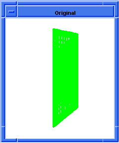  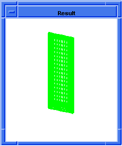
Figure. ds:rm-multi-face |
[Top]
ds:rm-patch
- Action
-
Removes and deletes a deformable model patch and its offspring from
the target's parent.
Filename-
scm/scmext/ds/dsscm.cpp
APIs-
api_dm_get_attrib_dm2acis,
api_dm_rm_patch
Syntax-
(ds:rm-patch owner [target=1])
Arg types-
Returns-
unspecified
Description
Removes and deletes a target deformable model patch and its offspring
from the owner of the target.
- The target argument specifies which deformable model to use in
a patch hierarchy. Valid values for target are:
-
1 = active deformable model
-
2 = root deformable model
-
-1 = active deformable model and offspring
-
-2 = root deformable model and offspring
-
Otherwise, the target is the deformable model whose tag identifier
equals target.
- Arguments
-
owner ACIS face or edge on which the deformable model lives.
-
target specifies which deformable model to use in a patch hierarchy.
Limitations-
This function cannot be used to remove a root deformable model shape.
It works only on children within the patch hierarchy.
; ds:rm-patch
; Build a test square spline face.
; (6x6 control points, x and y side length = 36)
(define dsmodel1 (ds:test-face 6 6 36 36 0))
;; dsmodel1
; Render the loads and constraints.
(ds:set-draw-state dsmodel1 2
(+ ds-draw-cstrns ds-draw-loads))
;; ()
; Add a rectangular patch to the parent shape.
; The new patch becomes the active shape.
(define patch1 (ds:add-patch dsmodel1 2 1
(par-pos 0.3 0.3) (par-pos 0.5 0.5)
(par-pos 0 0) 3))
;; patch1
(define cc2 (ds:add-pt-cstrn dsmodel1
patch1 "position" (par-pos 0.5 0.5)))
;; cc2
(ds:set-pt-xyz dsmodel1 cc2 0
(position 18 18 36))
;; 8
(ds:solve dsmodel1 2 1)
;; ()
; Now remove the first patch.
(ds:rm-patch dsmodel1 patch1)
;; ()
; The final shape consists only of the original
; parent shape. |
[Top]
ds:rm-tag-object
- Action
-
Removes a deformable model patch, load, or constraint tag object from
a deformable model.
Filename-
scm/scmext/ds/dsscm.cpp
APIs- api_dm_get_attrib_dm2acis
Syntax-
(ds:rm-tag-object owner tag)
Arg types-
Returns-
integer
Description
Removes the deformable model patch, load, or constraint tag object identified
by the input tag value from a deformable model. When the input tag value
identifies a tag object, this command sets the active deformable model of the patch
hierarchy to be the owner of the tag object.
This returns the tag type of the item deleted or a 0 when no items have
been deleted.
- Arguments
-
owner ACIS face or edge on which the deformable model lives.
-
tag value identifies tag object.
; ds:rm-tag-object
; Remove a load or constraint tag object
; from a deformable surface model.
; Build a test square spline face.
; (6x6 control points, x and y side length = 36)
(define dsmodel1 (ds:test-face 6 6 36 36 0))
;; dsmodel1
; Do not display entity / ds test face exists.
(define erase (entity:erase dsmodel1))
;; erase
; Render the loads and constraints.
(ds:set-draw-state dsmodel1 1
(+ ds-draw-cstrns ds-draw-loads))
;; ()
; Add a spring.
(define c1 (ds:add-spring dsmodel1 1
(par-pos 0.5 0.5) (position 18 18 15) 100))
;; c1
; The spring is displayed. Remove the spring.
(ds:rm-tag-object dsmodel1 c1)
;; 4
; The spring is deleted and is no longer displayed. |
[Top]
ds:set-alpha
- Action
-
Sets the resistance to stretch property values for a deformable model.
Filename-
scm/scmext/ds/dsscm.cpp
APIs- api_dm_get_attrib_dm2acis
Syntax-
(ds:set-alpha owner target=1 resistance-u [resistance-v atheta])
Arg types-
Returns-
unspecified
Description
Sets the stretching resistance of the target deformable model. resistance-u
is the resistance to stretch in a surface's u parameter direction.
resistance-v is the resistance to stretch in a surface's v parameter
direction. Only resistance-u values are used by deformable curves.
- The target argument specifies which deformable model to use in
a patch hierarchy. Valid values for target are:
-
1 = active deformable model
-
2 = root deformable model
-
-1 = active deformable model and offspring
-
-2 = root deformable model and offspring
-
Otherwise, the target is the deformable model whose tag identifier
equals target.
Larger alpha values tend to flatten out a surface. When resistance-u
equals resistance-v, a deformable surface's resistance to stretch is homogeneous.
It is the same in all directions within the surface and the atheta angle
parameter is not used.
When resistance-u does not equal resistance-v, a deformable surface's
resistance to stretch is inhomogeneous and the resistance to stretch can
be larger in one direction within the surface than in another. This homogeneous
effect can be rotated within the surface by the input angle atheta given
in degrees.
- Arguments
-
owner ACIS face or edge on which the deformable model lives.
-
target is the deformable model whose tag identifier equals target.
-
resistance-u is the resistance to stretch in a surface's u parameter
direction.
-
resistance-v is the resistance to stretch in a surface's v parameter
direction.
-
atheta is the input angle in degrees about which homogeneous effect
can be rotated.
Limitations-
Do not use negative numbers for au or av. atheta is in degrees.
; ds:set-alpha
; Add and use point constraint to square test face.
; Then vary alpha and beta values.
; Build a test square spline face.
; (6x6 control points, x and y side length = 36)
(define dsmodel1 (ds:test-face 6 6 36 36 0))
;; dsmodel1
; Do not display entity / ds test face exists.
(define erase (entity:erase dsmodel1))
;; erase
; Render the loads and constraints.
(ds:set-draw-state dsmodel1 1
(+ ds-draw-cstrns ds-draw-loads))
;; ()
; Add a pt-cstrn at the center and track it.
(define cc1 (ds:add-pt-cstrn dsmodel1
1 "position" (par-pos 0.5 0.5)))
;; cc1
(ds:set-pt-xyz dsmodel1 cc1 0
(position 18 18 35))
;; 8
; Compute a new deformable model position.
(ds:solve dsmodel1 1 1)
;; ()
; OUTPUT Original ; Change the alpha and beta parameters.
(ds:set-alpha dsmodel1 1 100)
;; ()
(ds:set-beta dsmodel1 1 0.001)
;; ()
(ds:solve dsmodel1 1 1)
;; ()
; The shape sharpens.
; OUTPUT Result
; Reverse the alpha and beta parameters.
(ds:set-alpha dsmodel1 1 0.001)
;; ()
(ds:set-beta dsmodel1 1 100)
;; ()
(ds:solve dsmodel1 1 1)
;; ()
; The shape softens
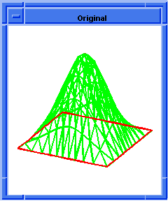  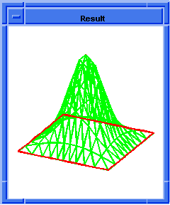
Figure. ds:set-alpha |
[Top]
ds:set-attractor-power
- Action
-
Sets the power for an attractor load identified by a tag value.
Filename-
scm/scmext/ds/dsscm.cpp
APIs- api_dm_get_attrib_dm2acis
Syntax-
(ds:set-attractor-power owner target=1 [power=2])
Arg types-
Returns-
integer
Description
When the tag identifies an attractor load, that load's power is set to
the input value. An attractor's power controls the locality of the
attractor's effect. Values of 0 and 1 are global. That is, the attractor
acts on its deformable shape no matter where it is located. Values
of 2 and higher are local, meaning that the attractor only acts on
the deformable model when the attractor is near the deformable shape.
Returns a 1 when an attractor's power is changed. Otherwise, it returns
a 0.
- Arguments
-
owner ACIS face or edge on which the deformable model lives.
-
target argument specifies which deformable model to use in a patch
hierarchy. Valid values for target are:
-
1 = active deformable model
-
2 = root deformable model
-
-1 = active deformable model and offspring
-
-2 = root deformable model and offspring
-
Otherwise, the target is the deformable model whose tag identifier
equals target.
-
power is a variable to set power.
; ds:set-attractor-power
; Define some helpful globals.
; Build a test square face with some tag objects.
; (6x6 control points, x and y side length = 36)
(define dsmodel1 (ds:test-face 6 6 36 36 0))
;; dsmodel1
(define erase (entity:erase dsmodel1))
;; erase
; Do not render the face.
; Add an attractor to deform the surface.
(define c1 (ds:add-attractor dsmodel1 1 1000))
;; c1
(ds:solve dsmodel1 1 1)
;; ()
; The surface deforms.
; Increase the attractor's power.
(ds:set-attractor-power dsmodel1 c1 0)
;; 0
(ds:solve dsmodel1 1 1)
;; () |
[Top]
ds:set-beta
- Action
-
Sets the bending resistance value for an owner's deformable model.
Filename-
scm/scmext/ds/dsscm.cpp
APIs- api_dm_get_attrib_dm2acis
Syntax-
(ds:set-beta owner target=1 bend-resu [bend-resv btheta])
Arg types-
Returns-
unspecified
Description
This extension sets the bending resistance for the target deformable
model. bend-resu is the resistance to bending in the surface's u
parameter direction. bend-resv is the resistance to bending in the surface's
v parameter direction. Deformable curves only use the bend-resu
value.
- The target argument specifies which deformable model to use in
a patch hierarchy. Valid values for target are:
-
1 = active deformable model
-
2 = root deformable model
-
-1 = active deformable model and offspring
-
-2 = root deformable model and offspring
-
Otherwise, the target is the deformable model whose tag identifier
equals target.
Large beta values cause the surface to deform to avoid sharp corners.
Zero beta values let the surface bend sharply at constraint points and
curves. For deformable surfaces, when bend-resu equals bend-resv, the
surface's resistance to bending is homogeneous; it is the same in all
directions within the surface. When bend-resu does not equal bend-resv,
the surface's resistance to bending is inhomogeneous. The non-homogeneous
effect can be rotated within the surface by the input angle btheta given
in degrees.
- Arguments
-
owner ACIS face or edge on which the deformable model lives.
-
target specifies which deformable model to use in a patch hierarchy.
-
bend-resu is the resistance to bending in the surface's u parameter
direction.
-
bend-resv is the resistance to bending in the surface's v parameter
direction.
-
btheta is an input angle where inhomogeneous effect can be rotated
within the surface.
Limitations-
Do not use negative bend-resu or bend-resv numbers. The angle btheta
is given in degrees.
; ds:set-beta
; Add and use point constraint to square test face.
; Vary alpha and beta values.
; Build a test square spline face.
; (6x6 control points, x and y side length = 36)
(define dsmodel1 (ds:test-face 6 6 36 36 0))
;; dsmodel1
; Do not display entity / ds test face exists.
(define erase (entity:erase dsmodel1))
;; erase
; Render the loads and constraints.
(ds:set-draw-state dsmodel1 1
(+ ds-draw-cstrns ds-draw-loads))
;; ()
; Add a pt-cstrn at the center and track it.
(define cc1 (ds:add-pt-cstrn dsmodel1
1 "position" (par-pos 0.5 0.5)))
;; cc1
(ds:set-pt-xyz dsmodel1 cc1 0
(position 18 18 35))
;; 8
; Compute a new deformable model position.
(ds:solve dsmodel1 1 1)
;; ()
; Change the alpha and beta parameters.
(ds:set-alpha dsmodel1 1 100)
;; ()
(ds:set-beta dsmodel1 1 0.001)
;; ()
(ds:solve dsmodel1 1 1)
;; ()
; The shape sharpens.
; OUTPUT Original ; Change the alpha and beta parameters.
(ds:set-alpha dsmodel1 1 0.001)
;; ()
(ds:set-beta dsmodel1 1 100)
;; ()
(ds:solve dsmodel1 1 1)
;; ()
; The shape softens.
; OUTPUT Result
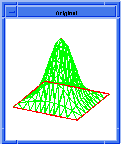  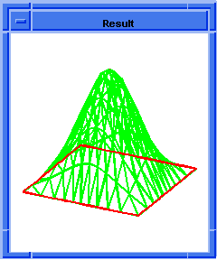
Figure. ds:set-beta |
[Top]
ds:set-comb-graphics
- Action
-
Sets the number of points and the gain used in the deformable model's
rendering of curvature combs.
Filename-
scm/scmext/ds/dsscm.cpp
APIs- api_dm_get_attrib_dm2acis
Syntax-
(ds:set-comb-graphics owner target=1 elem-point-count
gain=1)
Arg types-
Returns-
unspecified
Description
Sets the number of points and scaling gain used to render the curvature
comb for a target deformable model.
- The target argument specifies which deformable model to use in
a patch hierarchy. Valid values for target are:
-
1 = active deformable model
-
2 = root deformable model
-
-1 = active deformable model and offspring
-
-2 = root deformable model and offspring
-
Otherwise, the target is the deformable model whose tag identifier
equals target.
Curvature combs constitute a graphical
representation of the parameter space curvature properties of the curve
constraints. A curvature comb is made up of a set of vectors drawn from
the curve in the direction of principal curvature. The magnitude of the
vector is the curvature. These combs are then projected through the deformable
surface shape into three dimensional space for rendering, which tends
to distort them as the surface is manipulated. The number of vectors drawn
per element is specified by elem-point-count. gain is an additional gain
factor used to scale the curvature comb for viewing convenience.
- Arguments
-
owner ACIS face or edge on which the deformable model lives.
-
target specifies which deformable model to use in a patch hierarchy.
-
elem-point-count is the number of vectors drawn per element.
-
gain is an additional factor to scale the curvature comb for viewing
convenience.
Limitations-
Do not use negative numbers.
; ds:set-comb-graphics
; Build a test square face with some tag objects.
; (6x6 control points, x and y side length = 36)
(define dsmodel1 (ds:test-face 6 6 36 36 0))
;; dsmodel1
; Do not display entity / ds test face exists
(define erase (entity:erase dsmodel1))
;; erase
; Render the loads and constraints.
(ds:set-draw-state dsmodel1 1
(+ ds-draw-cstrns ds-draw-loads
ds-draw-cstrn-norms))
;; ()
; Replace the default edge constraints with
; a circle constraint.
(ds:toggle-cstrn dsmodel1 1)
;; 0
(ds:toggle-cstrn dsmodel1 2)
;; 0
(ds:toggle-cstrn dsmodel1 3)
;; 6
(ds:toggle-cstrn dsmodel1 4)
;; 6
(ds:add-circ-cstrn dsmodel1 1 "position"
(par-pos 0.5 0.5) (par-pos 0 0.3)
(par-pos 0.3 0))
;; 7
(ds:set-draw-state dsmodel1 1
(+ ds-draw-cstrns ds-draw-loads
ds-draw-cstrn-norms))
;; ()
; Adjust the curvature plot graphics.
(ds:set-comb-graphics dsmodel1 1 20 -1.0)
;; ()
; The comb is drawn pointing to the convex side. |
[Top]
ds:set-cstrn-behavior
- Action
-
Sets the behavior of what is constrained on a deformable model between
"position", "tangent", and "pos_tan".
Filename-
scm/scmext/ds/dsscm.cpp
APIs- api_dm_get_attrib_dm2acis
Syntax-
(ds:set-cstrn-behavior owner tag behavior)
Arg types-
Returns-
boolean
Description
Changes the behavior of what is constrained on a deformable model between
"position", "tangent", or "pos_tan". This returns #t if the change is
allowed, and #f if it is not allowed or if the target is not a constraint.
The input argument owner is the face or edge being sculpted. tag is
the identifier for the constraint to modify. When the tag identifier identifies
a constraint, the deformable model in the patch hierarchy which contains
the constraint becomes the active deformable model.
- behavior specifies whether the position and/or the tangents of
the deformable model are constrained. The valid string values for behavior
are:
-
for lone behaviors:
-
"position" or "p"
-
"tangent" or "t"
-
"tan2" or "t2"
-
"normal" or"n"
-
(for curves turns on "tangent")
-
"binormal" or "b"
-
"curvature" or "c"
-
(turns on "tangent" and "normal")
-
"curv2" or "c2"
-
(turns on "tan2" and "normal")
-
for 2 behavior combinations:
-
"pos_tan" or "pt"
-
"pos_tan2" or "pt2"
-
pos_norm" or "pn"
-
"pos_binorm" or "pb"
-
"pos_cur" or "pc"
-
(turns on "tangent")
-
"pos_cur2" or "pc2"
-
(turns on "tan2")
-
"tan_tan2" or "tt2"
-
"tan_norm" or "tn"
-
"tan_binorm" or "tb"
-
"tan2_norm" or "t2n"
-
"cur_cur2" or "cc2"
-
for 3 behavior combinations:
-
"pos_tan_tan2" or "ptt2"
-
"pos_tan_norm" or "ptn"
-
"pos_tan_binorm" or "ptb"
-
"pos_tan2_norm" or "pt2n"
-
"pos_tan2_cur" or "pt2c"
-
"pos_tan_cur2" or "ptc2"
-
"pos_cur_cur2" or "pcc2"
-
"tan_tan2_norm" or "tt2n"
-
"pos_tan_tan2_norm" or "ptt2n"
- For link constraints one must specify one of three states for six
different parameters. The valid states are:
o = free-
f = fixed
-
l = linked
- The six different parameters to set are:
crv1_curvature-
crv2_curvature
-
crv1_position
-
crv1_tangent
-
crv2_position
-
crv2_tangent
That makes 162 different allowed behavior states for a link constraint.
These states can be specified by the string "pos_?_?_tan_?_?" where the
question marks can be one of "off" or "o", "fixed" or "f", or "linked"
or "l". As an example, the string "pos_linked_linked_tan_off_off" or "pll_too"
sets the behavior to DM_POS_LINKED | DM_POS_2_LINKED | DM_TAN_FREE | DM_TAN_2_FREE.
- Arguments
-
behavior specifies whether the position and/or the tangents of the
deformable model are constrained.
-
owner ACIS face or edge on which the deformable model lives.
-
tag is the identifier for the constraint to modify.
; ds:set-cstrn-behavior
; Add to a square test face a parabolic crv-load
; and use it.
; Build a test square spline face.
; (6x6 control points, x and y side length = 36)
(define dsmodel1 (ds:test-face 6 6 36 36 0))
;; dsmodel1
; Do not display entity / ds test face exists
(define erase (entity:erase dsmodel1))
;; erase
; Render the loads and constraints.
(ds:set-draw-state dsmodel1 1
(+ ds-draw-cstrns ds-draw-loads))
;; ()
; Add a pt-cstrn at the center of the parent and
; track it.
(define cc1 (ds:add-pt-cstrn dsmodel1
1 "position" (par-pos 0.5 0.5)))
;; cc1
(ds:set-pt-xyz dsmodel1 cc1 0
(position 16 16 10))
;; 8
; Compute a new deformable model position.
(ds:solve dsmodel1 1 1)
;; ()
; OUTPUT Original
; Change an edge constraint's behavior.
(ds:set-cstrn-behavior dsmodel1 cc1 "pos_tan")
;; #t
; Track the point constraint and see how the
; edge constraint behaves differently.
(ds:set-pt-xyz dsmodel1 cc1 0
(position 16 16 0))
;; 8
(ds:solve dsmodel1 1 1)
;; ()
; OUTPUT Result
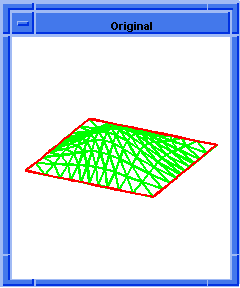  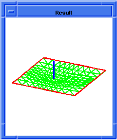
Figure. ds:set-cstrn-behavior |
[Top]
ds:set-cstrn-domain-dir
- Action
-
Sets the domain space direction within a surface for a point constraint's
tangent or curvature behavior.
Filename-
scm/scmext/ds/dsscm.cpp
APIs- api_dm_get_attrib_dm2acis
Syntax-
(ds:set-cstrn-domain-dir owner tag uv-dir point-index)
Arg types-
Returns-
boolean
Description
Changes the domain direction for a point constraint's tangent and curvature
behaviors. This direction is only used for point constraints applied to
a surface.
- The tangent and curvature constraint behaviors for a point constraint
applied to a surface constrain the surface geometric properties in a direction
at a point on the surface. A surface can have two independent tangent
and/or curvature constraints as long as the domain direction for each
constraint is different. To completely specify a tangent or curvature
point constraint behavior on a surface the end-user must supply the following
set of information:
1. location on the surface, given by a parametric position-
2. a direction on the surface, given by a parametric vector
-
3. a value for the geometric property being constrained,
-
3a. for tangent constraints; an image space vector used to specify
the image space direction of the tangent.
-
3b. for curvature constraints; the curvature value, an image
space vector used to
specify the direction of the surface
normal, and a 2nd image space vector used to specify the surface tangent
at that point.
This function sets the domain direction for the tangent and curvature
behaviors of a point constraint on a surface. The input arguments owner
and tag specify which point constraint to modify within a deformable modeling
hierarchy. The input argument point-index specifies which domain direction
to modify; its values must be 1 or 2 for directions 1 and 2. And the input
argument domain-dir specifies the new domain direction; it does not have
to be a unit-vector on input. The two domain directions for a single point
constraint must be different. The default values for a point constraint's
domain directions are the u and v vectors,
domain1-dir default = [1, 0] ('u' vector direction)
domain2-dir default = [0, 1] ('v' vector direction)
- Arguments
-
owner ACIS face or edge on which the deformable model lives.
-
tag specifies which point constraint to modify within a deformable modeling
hierarchy.
-
uv-direction specifies the new domain direction.
-
point-index specifies which domain direction to modify
; ds:set-cstrn-domain-dir
; Add to a square test face a parabolic crv-load
; and use it.
; Build a test square spline face.
; (6x6 control points, x and y side length = 36)
(define dsmodel1 (ds:test-face 6 6 36 36 0))
;; dsmodel1
; Do not display entity / ds test face exists.
(define erase (entity:erase dsmodel1))
;; erase
; Render the loads and constraints.
(ds:set-draw-state dsmodel1 1
(+ ds-draw-cstrns ds-draw-loads))
;; ()
; Add a pt-cstrn at the center of the parent and
; track it.
(define cc1 (ds:add-pt-cstrn dsmodel1
1 "position" (par-pos 0.5 0.5)))
;; cc1
(ds:set-pt-xyz dsmodel1 cc1 0
(position 16 16 10))
;; 8
; Compute a new deformable model position.
(ds:solve dsmodel1 1 1)
;; ()
; OUTPUT Original
; Set the domain-dir for direction 1.
(ds:set-cstrn-domain-dir dsmodel1 cc1
(par-pos .5 .5) 1)
;; #t
; Change an edge constraint's behavior.
(ds:set-cstrn-behavior dsmodel1 cc1 "pos_tan")
;; #t
; Tract the point constraint.
(ds:set-pt-xyz dsmodel1 cc1 0
(position 16 16 0))
;; 8
(ds:solve dsmodel1 1 1)
;; ()
; OUTPUT Result
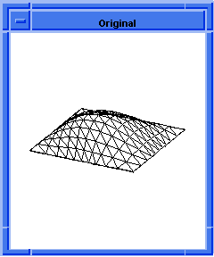  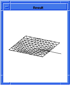
Figure. ds:set-cstrn-domain-dir |
[Top]
ds:set-cstrn-state
- Action
-
Sets whether a constraint on a deformable model is enabled or disabled.
Filename-
scm/scmext/ds/dsscm.cpp
APIs- api_dm_get_attrib_dm2acis
Syntax-
(ds:set-cstrn-state owner tag state)
Arg types-
Returns-
boolean
Description
Sets whether a constraint on a deformable model is enabled or disabled.
When state is 1, the constraint is enabled; when state is 0, the constraint
is disabled.
The input argument owner is the face or edge being sculpted. tag is
the identifier for the constraint to modify. When the tag identifier identifies
a constraint, the deformable model in the patch hierarchy which contains
the constraint becomes the active deformable model.
This extension returns a #t when the change is allowed and #f when the
change is prohibited or when the target is not a constraint.
- Arguments
-
owner ACIS face or edge on which the deformable model lives.
-
state to enable or disable constraint.
-
tag identifier identifies a constraint, the deformable model in the
patch hierarchy which contains the constraint becomes the active deformable
model.
; ds:set-cstrn-state
; Add to a square test face a parabolic crv-load
; and use it.
; Build a test square spline face.
; (6x6 control points, x and y side length = 36)
(define dsmodel1 (ds:test-face 6 6 36 36 0))
;; dsmodel1
; Do not display entity / ds test face exists.
(define erase (entity:erase dsmodel1))
;; erase
; Render the loads and constraints.
(ds:set-draw-state dsmodel1 1
(+ ds-draw-cstrns ds-draw-loads))
;; ()
; Add a pt-cstrn at the center of the parent and
; track it.
(define cc1 (ds:add-pt-cstrn dsmodel1
1 "position" (par-pos 0.5 0.5)))
;; cc1
(ds:set-pt-xyz dsmodel1 cc1 0
(position 16 16 10))
;; 8
; Compute a new deformable model position.
(ds:solve dsmodel1 1 1)
;; ()
; Disable the point constraint and solve again.
(ds:set-cstrn-state dsmodel1 cc1 0)
;; #t
(ds:solve dsmodel1 1 1)
;; ()
; The shape deforms without the influence of the
; pt-cstrn. |
[Top]
ds:set-default-shape
- Action
-
Sets the default deformable model shape to either zero or the current
shape.
Filename-
scm/scmext/ds/dsscm.cpp
APIs- api_dm_get_attrib_dm2acis
Syntax-
(ds:set-default-shape owner target=1 shape-flag)
Arg types-
Returns-
unspecified
Description
Sets the target deformable model of the owner as the default shape.
When shape-flag is 0, the default shape is zeroed. When shape-flag is 1,
the current shape is captured as the default shape. As a side-effect of
capturing a default shape, all load gains are set to zero.
- The target argument specifies which deformable model to use in
a patch hierarchy. Valid values for target are:
-
1 = active deformable model
-
2 = root deformable model
-
-1 = active deformable model and offspring
-
-2 = root deformable model, siblings, and offspring
-
Otherwise, the target is the deformable model whose tag identifier
equals target.
The default shape is the shape to which the surface is attempting to
deform. The surface will always deform to the default shape when its shape
is computed without any loads or constraints.
Objects, like soap films, for example, attempt to minimize their area.
Their default shape is a zero area flat element. The shape of such deformable
models is completely determined by the applied constraints and loads.
This behavior can be mimicked in deformable surfaces by setting the default
shape to zero. Default shapes tend to be very smooth.
Most objects, like steel plates, rubber balls, and plastic baubles,
have a natural default shape. Loads and constraints pull the object away
from its natural shape. This behavior may be mimicked by capturing a nonzero
default shape with this extension.
Large deformations away from the default shape due to pressure loads
may become unstable. To get such shapes in a stable manner, use a sequence
of moderate pressure gains and default shape captures to build a very
large deformation. Alternatively, use spring loads and curve loads for
large deformations and reserve pressure loads for relatively small deformations.
- Arguments
-
shape-flag is the flag to specify the shape.
-
owner ACIS face or edge on which the deformable model lives.
-
target specifies which deformable model to use in a patch hierarchy.
; ds:set-default-shape
; Build a test square face with some tag objects.
; (6x6 control points, x and y side length = 36)
(define dsmodel1 (ds:test-face 6 6 36 36 0))
;; dsmodel1
; Do not display entity / ds test face exists
(define erase (entity:erase dsmodel1))
;; erase
; Render the control-points and tag objects.
(ds:set-draw-state dsmodel1 1
(+ ds-draw-cpts ds-draw-cstrns ds-draw-loads))
;; ()
(ds:solve dsmodel1 1 1)
;; ()
; The control points do not move because
; the surface is created with a default shape.
; OUTPUT Original
; Replace the default edge constraints with corner
; point constraints.
(ds:toggle-cstrn dsmodel1 1)
;; 0
(ds:toggle-cstrn dsmodel1 2)
;; 0
(ds:toggle-cstrn dsmodel1 3)
;; 6
(ds:toggle-cstrn dsmodel1 4)
;; 6
(ds:add-pt-cstrn dsmodel1 1 "position"
(par-pos 0 0))
;; 7
(ds:add-pt-cstrn dsmodel1 1 "position"
(par-pos 0 1))
;; 8
(ds:add-pt-cstrn dsmodel1 1 "position"
(par-pos 1 0))
;; 9
(ds:add-pt-cstrn dsmodel1 1 "position"
(par-pos 1 1))
;; 10
; Eliminate the default shape behavior.
(ds:set-default-shape dsmodel1 1 0)
;; ()
(ds:set-delta dsmodel1 1 0)
;; ()
(ds:solve dsmodel1 1 1)
;; ()
; OUTPUT Result
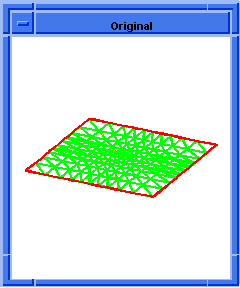  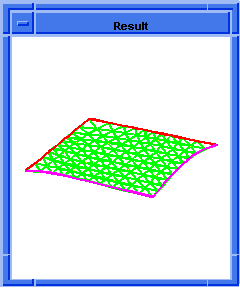
Figure. ds:set-default-shape |
[Top]
ds:set-delta
- Action
-
Sets the resistance to move from the default shape for a deformable
model.
Filename-
scm/scmext/ds/dsscm.cpp
APIs- api_dm_get_attrib_dm2acis
Syntax-
(ds:set-delta owner target=1 delta)
Arg types-
Returns-
unspecified
Description
Sets the resistance to move from the default shape for the target deformable
model of the owner.
- The target argument specifies which deformable model to use in
a patch hierarchy. Valid values for target are:
-
1= active deformable model
-
2= root deformable model
-
-1= active deformable model and offspring
-
-2= root deformable model and offspring
-
Otherwise, the target is the deformable model whose tag identifier
equals target.
Enforcing the default shape is similar to having a distributed spring
that acts between every point on the default shape and every point on
the deformed surface.
- Arguments
-
delta large delta value causes all those points to lie close
together. Setting the delta value to zero turns off the effect.
-
owner ACIS face or edge on which the deformable model lives.
-
target specifies which deformable model to use in a patch hierarchy.
Limitations-
Do not use negative numbers.
; ds:set-delta
; Set the resistance to move from the default
; shape value for a deformable surface model.
; Build a test square face with a constraint point.
; (6x6 control points, x and y side length = 36)
(define dsmodel1 (ds:test-face 6 6 36 36 0))
;; dsmodel1
; Do not display entity / ds test face exists.
(define erase (entity:erase dsmodel1))
;; erase
; Render the loads and constraints.
(ds:set-draw-state dsmodel1 1
(+ ds-draw-cstrns ds-draw-loads))
;; ()
(define c1 (ds:add-pt-cstrn dsmodel1
1 "position" (par-pos 0.5 0.5)))
;; c1
(ds:set-pt-xyz dsmodel1 c1 0
(position 18 18 20))
;; 8
; Solve for the shape with default-shape.
(ds:set-delta dsmodel1 1 0.0)
;; ()
(ds:solve dsmodel1 1 1)
;; ()
; The surface deforms.
; OUTPUT Original
(ds:set-delta dsmodel1 1 20000)
;; ()
(ds:solve dsmodel1 1 1)
;; ()
; The deformation becomes more localized about the
; constraint point.
; OUTPUT Result
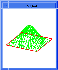  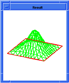
Figure. ds:set-delta |
[Top]
ds:set-draw-grid
- Action
-
Sets the number of polygons in the mesh used to render the shape of
a deformable model.
Filename-
scm/scmext/ds/dsscm.cpp
APIs- api_dm_get_attrib_dm2acis
Syntax-
(ds:set-draw-grid owner target=1 grid-polygon-u [grid-polygon-v])
Arg types-
Returns-
unspecified
Description
Sets the number of polygons in the mesh used to render the deformable
shape of a target deformable model.
- The target argument specifies which deformable model to use in
a patch hierarchy. Valid values for target are:
-
1= active deformable model
-
2= root deformable model
-
-1= active deformable model and offspring
-
-2= root deformable model and offspring
-
Otherwise, the target is the deformable model whose tag identifier
equals target.
For deformable surfaces, gridpolygonu and gridpolygonv
are used. For deformable curves, only gridpolygonu is used.
- Arguments
-
grid-polygon-uis the number of grid polygons in the v parametric direction.
-
grid-polygon-vis the number of grid polygons in the v parametric direction.
-
target specifies which deformable model to use in a patch hierarchy.
; ds:set-draw-grid
; Add to a square test face a parabolic crv-load
; and use it.
; Build a test square spline face.
; (6x6 control points, x and y side length = 36)
(define dsmodel1 (ds:test-face 6 6 36 36 0))
;; dsmodel1
; Do not display entity / ds test face exists.
(define erase (entity:erase dsmodel1))
;; erase
; Render the loads and constraints.
(ds:set-draw-state dsmodel1 1
(+ ds-draw-cstrns ds-draw-loads))
;; ()
; OUTPUT Original
(ds:set-draw-grid dsmodel1 1 3 3)
;; ()
; OUTPUT Rougher
(ds:get-draw-grid dsmodel1 1)
;; (3 3)
; The surface rendering gets smoother as polygon
; count increases.
(ds:set-draw-grid dsmodel1 1 8 8)
;; ()
(ds:set-draw-grid dsmodel1 1 12 12)
;; ()
; OUTPUT Smoother
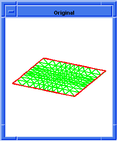  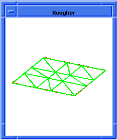
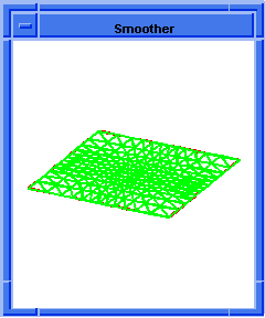
Figure. ds:set-draw-grid |
[Top]
ds:set-draw-state
- Action
-
Sets the combination of deformable model data to be rendered for a
deformable model.
Filename-
scm/scmext/ds/dsscm.cpp
APIs- api_dm_get_attrib_dm2acis
Syntax-
(ds:set-draw-state owner target=1 ctpoint-flag)
Arg types-
Returns-
unspecified
Description
Sets the combination of deformable model data to be rendered for the
owner's target deformable model.
- The target argument specifies which deformable model to use in
a patch hierarchy. Valid values for target are:
-
1= active deformable model
-
2= root deformable model
-
-1= active deformable model and offspring
-
-2= root deformable model and offspring
-
Otherwise, the target is the deformable model whose tag identifier
equals target.
The argument ctpoint-flag is a bitwise of the following values to display
control points, gauss points (used for numerical integration), constraints,
and loads.
| ds-draw-cpts |
draw control points bit |
| ds-draw-seams |
draw seam constraints bit |
| ds-draw-cstrns |
draw constraints bit |
| ds-draw-loads |
draw loads bit |
| ds-draw-curve-comb |
draw curve curvature comb bit |
| ds-draw-elems |
draw element boundaries bit |
The following call will cause the constraints, seams, loads, and tangents
for the active deformable model to be drawn:
(ds:set-draw-state ds-model 1 (+ ds-draw-cstrn ds-draw-seams ds-draw-loadsc
ds-draw-cstrn-norms))
- Arguments
-
owner ACIS face or edge on which the deformable model lives.
-
target specifies which deformable model to use in a patch hierarchy
-
ctpoint-flag is a bitwise of the following values to display control
points, gauss points (used for numerical integration), constraints, and
loads.
; ds:set-draw-state
; Set the combination of deformable model data
; to be rendered.
; Build a test square face with some tag objects.
; (6x6 control points, x and y side length = 36)
(define dsmodel1 (ds:test-face 6 6 36 36 0))
;; dsmodel1
; Do not display entity / ds test face exists.
(define erase (entity:erase dsmodel1))
;; erase
; Increase the icon rendering size.
(ds:set-icon-radius dsmodel1 3)
;; ()
; Render the loads and constraints.
(ds:set-draw-state dsmodel1 1
(+ ds-draw-cstrns ds-draw-loads))
;; ()
; Render the control points (drawn in yellow).
(ds:set-draw-state dsmodel1 1 ds-draw-cpts)
;; ()
; Render only the load and constraint tag objects.
(ds:set-draw-state dsmodel1 1
(+ ds-draw-cstrns ds-draw-loads))
;; ()
; 4 red constraint curves are drawn on the face's
; boundary.
; Add some more tag objects.
(ds:add-pt-cstrn dsmodel1 1 "position"
(par-pos 0.5 0.5))
;; 7
(ds:add-spring dsmodel1 1 (par-pos 0.3 0.3)
(position 10 10 15) 200)
;; 8
; OUTPUT Original
; These are drawn as they are added. A red point for
; the constraint point and a cyan line for the
; spring. Add the control points to the image.
(ds:set-draw-state dsmodel1 1
(+ ds-draw-cpts ds-draw-cstrns ds-draw-loads))
;; ()
(ds:solve dsmodel1 1 1)
;; ()
; OUTPUT Result
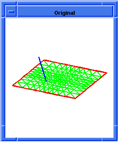  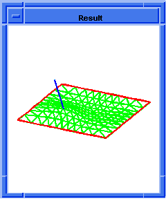
Figure. ds:set-draw-state |
[Top]
ds:set-dynamics
- Action
-
Sets the time integral data for a deformable surface model time simulation
including effective mass and damping and time step size.
Filename-
scm/scmext/ds/dsscm.cpp
APIs- api_dm_get_attrib_dm2acis
Syntax-
(ds:set-dynamics owner target=1 timestep-dt mass damp)
Arg types-
Returns-
unspecified
Description
Sets the time step size and effective mass and damping for a face's
deformable surface.
- The target argument specifies which deformable model to use in
a patch hierarchy. Valid values for target are:
-
1= active deformable model
-
2= root deformable model
-
-1= active deformable model and offspring
-
-2= root deformable model and offspring
-
Otherwise, the target is the deformable model whose tag identifier
equals target.
Each iteration of ds:solve
face integrates the equations of motion for
a deformable surface by one time step. Large time step values leap
from one equilibrium position to another. Small time step values can be
used to show the system moving from one equilibrium position to the next.
Increasing the amount of damping increases the rate at which energy is
taken from the system. Very large damping values will cause the system
to move very slowly. Very small damping values will cause the system to
ring. Increasing the systems mass will increase its tendency to ring,
that is, overshoot and bounce back. These effects can be used to create realistic
time-based simulations of moving deforming objects.
- Arguments
-
owner ACIS face or edge on which the deformable model lives.
-
target specifies which deformable model to use in a patch hierarchy.
-
timestep-dt is a timestep value. Large time step values leap from one
equilibrium position to another. Small time step values can be used to
show the system moving from one equilibrium position to the next.
-
mass is system mass.
-
damp to set the rate at which energy is taken from the system.
Limitations-
Do not use 0 or negative values for time; do not use negative values
for damping or mass.
; ds:set-dynamics
; Build a test square face with some tag objects
; (6x6 control points, x and y side length = 36)
(define dsmodel1 (ds:test-face 6 6 36 36 0))
;; dsmodel1
; Do not display entity / ds test face exists.
(define erase (entity:erase dsmodel1))
;; erase
; Render the loads and constraints.
(ds:set-draw-state dsmodel1 1
(+ ds-draw-cstrns ds-draw-loads))
;; ()
; Change the shape by tracking a point constraint.
(define c1 (ds:add-pt-cstrn dsmodel1 1
"position" (par-pos 0.5 0.5)))
;; c1
(ds:set-pt-xyz dsmodel1 c1 0
(position 18 18 30))
;; 8
(ds:solve dsmodel1 1 1)
;; ()
; Change the dynamic parameters to cause overshoot
; and wobble in future changes in shape.
(ds:set-dynamics dsmodel1 1 0.1 40.0 0.5)
;; ()
; Toggle point constraint to get the shape in motion.
(ds:toggle-cstrn dsmodel1 c1)
;; 8
; Repeated ds:solve calls show the surface moving
; which overshoots and bounces back to the origin.
; A programming interface with a repeating solve and
; render loop can show this as an animation.
(ds:solve dsmodel1 1 1)
;; ()
(ds:solve dsmodel1 1 1)
;; ()
(ds:solve dsmodel1 1 1)
;; ()
(ds:solve dsmodel1 1 1)
;; ()
(ds:solve dsmodel1 1 1)
;; ()
(ds:solve dsmodel1 1 1)
;; ()
; Use more (ds:solve) calls to see the motion decay.
; Get the current set of dynamics parameters.
(ds:get-dynamics dsmodel1 1)
;; (0.1 40 0.5) |
[Top]
ds:set-epsilon
- Action
-
Sets the epsilon fairing parameter for a deformable model.
Filename-
scm/scmext/ds/dsscm.cpp
APIs- api_dm_get_attrib_dm2acis
Syntax-
(ds:set-epsilon owner target epsilon)
Arg types-
Returns-
unspecified
Description
epsilon regulates a shape fairing (energy minimization) term that is
used to dampen control point oscillations in high degree splines (degree>8).
Like the primary fairing terms, alpha and beta, epsilon should be 0
or positive. epsilon is considered a supplement to the alpha and beta
shape fairing terms, and should be relatively small compared to beta,
the chief shape fairing term.
- Arguments
-
owner ACIS face or edge on which the deformable model lives.
-
target specifies which deformable model to use in a patch hierarchy.
-
epsilon regulates a shape fairing (energy minimization) term that is
used to dampen control point oscillations in high degree splines (degree>8).
Limitations-
Do not use negative numbers for epsilon.
; ds:set-epsilon
; Create a block.
(define b1 (solid:block (position 5 10 15)
(position 10 20 30)))
;; b1
; pick a face
(ray:queue 8.00781 14.6484 500 0 0 -1 1)
;; #[ray (8.00781 14.6484 500) (0 0 -1)]
(define ds-model (pick-face))
;; ds-model
(define eps (ds:get-epsilon ds-model 2))
;; eps
(print eps)
;; 0
(ds:set-epsilon ds-model 2 0.1)
;; ()
(define eps (ds:get-epsilon ds-model 2))
;; eps
(print eps)
;; 0.1 |
[Top]
ds:set-gamma
- Action
-
Sets the owner's rate of change of the resistance to bending parameter
for the target deformable model.
Filename-
scm/scmext/ds/dsscm.cpp
APIs- api_dm_get_attrib_dm2acis
Syntax-
(ds:set-gamma owner target=1 [gamma])
Arg types-
Returns-
unspecified
Description
Sets the owner's rate of change of the resistance to bending parameter
for the target deformable model. The gamma term is used in conjunction
with curvature constraints and C2 seams to connect parent and child patches
together with C2 continuity. The curvature constraint affects the curvature
of the deformable model only at the point at which it is applied. The
gamma-weighted resistance to bending changes will blend the curvature
constraint effect in with the rest of the deformable modeling constraint.
When gamma is zero, it has no effect on the system.
- The target argument specifies which deformable model to use in
a patch hierarchy. Valid values for target are:
-
1= active deformable model
-
2= root deformable model
-
-1= active deformable model and offspring
-
-2= root deformable model and offspring
-
Otherwise, the target is the deformable model whose tag identifier
equals target.
- Arguments
-
owner ACIS face or edge on which the deformable model lives.
-
target specifies which deformable model to use in a patch hierarchy.
-
gamma is used in conjunction with curvature constraints and C2 seams
to connect parent and child patches together with C2 continuity.
Limitations-
Do not use negative numbers.
; ds:set-gamma
; Define some helpful globals
; Build a test square face with a constraint point.
; (6x6 control points, x and y side length = 36)
(define dsmodel1 (ds:test-face 5 5 36 36 0))
;; dsmodel1
(define erase (entity:erase dsmodel1))
;; erase
; Do not render the face.
(define c1 (ds:add-pt-cstrn dsmodel1 1
"position" (par-pos .5 .5)))
;; c1
(ds:set-pt-xyz dsmodel1 1 c1
(position 18 18 20))
;; 0
; Solve for the shape with and with default-shape.
(ds:set-gamma dsmodel1 1 0.0)
;; ()
(ds:solve dsmodel1 1 1)
;; ()
; The surface deforms.
(ds:set-gamma dsmodel1 1 10)
;; ()
(ds:solve dsmodel1 1 1)
;; () |
[Top]
ds:set-icon-radius
- Action
-
Sets the icon radius to be used to render tag object information.
Filename-
scm/scmext/ds/dsscm.cpp
APIs- api_dm_get_attrib_dm2acis
Syntax-
(ds:set-icon-radius owner radius)
Arg types-
Returns-
unspecified
Description
Sets the size for rendering the face's deformable model icons. Point
icons are drawn for point constraints and point pressure loads. Curve
icons are drawn for curve constraints, curve loads and spring loads.
- Arguments
-
owner ACIS face or edge on which the deformable model lives.
-
radius is the radius of the rendering face.
; ds:set-icon-radius
; Set the rendering size of deformable model point
; and curve icons.
; Build a test square face with some tag objects.
; (6x6 control points, x and y side length = 36)
(define dsmodel1 (ds:test-face 6 6 36 36 0))
;; dsmodel1
; Do not display entity / ds test face exists.
(define erase (entity:erase dsmodel1))
;; erase
; Render the loads and constraints.
(ds:set-draw-state dsmodel1 1
(+ ds-draw-cstrns ds-draw-loads))
;; ()
; Render the control points, loads and constraints.
(ds:set-draw-state dsmodel1 1
(+ ds-draw-cpts ds-draw-cstrns ds-draw-loads))
;; ()
; Change the icon size.
(ds:set-icon-radius dsmodel1 1)
;; ()
(ds:set-icon-radius dsmodel1 5)
;; ()
; OUTPUT Original
(ds:set-icon-radius dsmodel1 9)
;; ()
; OUTPUT Result
; The icon sizes render progressively larger.
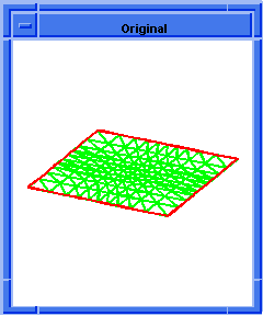  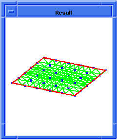
Figure. ds:set-icon-radius |
[Top]
ds:set-interior-state
- Action
-
Sets the interior state value to allow or prohibit C0 bending within
the interior of a deformable model.
Filename-
scm/scmext/ds/dsscm.cpp
APIs- api_dm_get_attrib_dm2acis
Syntax-
(ds:set-interior-state owner target=1 interior-state-flag)
Arg types-
Returns-
unspecified
Description
Assigns the input flag value to the target deformable model's interior
state value.
When interior-state-flag = 0, the deformable model is allowed to bend with
C0 discontinuity between elements. For Bsplines and NURBs, C0 discontinuity
within a surface can be achieved by increasing the knot count at an internal
knot boundary.
When interior-state-flag = 1, the deformable model prohibits C0 bending between
elements by adding C1 internal tangent constraints between any elements
whose internal representation will allow a C0 bend. For B-splines and
NURBs, this means that the deformation will be at least C1 everywhere
even if the underlying representation has multiple knots that would normally
allow a C0 internal bend.
- The target argument specifies which deformable model to use in
a patch hierarchy. Valid values for target are:
-
1= active deformable model
-
2= root deformable model
-
-1= active deformable model and offspring
-
-2= root deformable model and offspring
-
Otherwise, the target is the deformable model whose tag identifier
equals target.
- Arguments
-
interior-state-flag specifies interior state value.
-
owner ACIS face or edge on which the deformable model lives.
-
target specifies which deformable model to use in a patch hierarchy.
; ds:set-interior-state
; Build a test square face with some tag objects.
; (6x6 control points, x and y side length = 36)
(define dsmodel1 (ds:test-face 6 6 36 36 0))
;; dsmodel1
; Do not display entity / ds test face exists.
(define erase (entity:erase dsmodel1))
;; erase
; Render the control-points and tag objects.
(ds:set-draw-state dsmodel1 1
(+ ds-draw-cpts ds-draw-cstrns ds-draw-loads))
;; ()
(ds:solve dsmodel1 1 1)
;; ()
(ds:get-interior-state dsmodel1)
;; 1
; The system returns the default interior state
; value.
(ds:set-interior-state dsmodel1 1 0)
;; ()
(ds:get-interior-state dsmodel1)
; The assigned interior state value is returned.
;; 0 |
[Top]
ds:set-load-gain
- Action
-
Sets the gain of a load tag object.
Filename-
scm/scmext/ds/dsscm.cpp
APIs- api_dm_get_attrib_dm2acis
Syntax-
(ds:set-load-gain owner tag gain [increment])
Arg types-
Returns-
unspecified
Description
Sets or increments the gain on one or more load tag objects in the face's
deformable model. When load-tag = -2, all point pressure load gains will
be modified. When load-tag = -3, all spring load gains will be modified.
When load-tag is a positive integer, only the tag object with that tag
identifier will be modified. When the tag identifier recognizes a tag
object, the deformable model in the patch hierarchy which contains the
tag object becomes the active deformable model.
When the increment argument is used (regardless of its value), the modified
load gains are incremented by the input gain value. When the increment
argument is omitted, the modified load gains are set to the input
gain value.
- Arguments
-
owner ACIS face or edge on which the deformable model lives.
-
load-tag is the point pressure tag.
-
gain is a force of amplitude.
-
increment is the incremental value to modify load gain.
; ds:set-load-gain
; Set the gain of a load tag object.
; Build a test square face with some tag objects.
; (6x6 control points, x and y side length = 36)
(define dsmodel1 (ds:test-face 6 6 36 36 0))
;; dsmodel1
; Do not display entity / ds test face exists.
(define erase (entity:erase dsmodel1))
;; erase
; Render the loads and constraints.
(ds:set-draw-state dsmodel1 1
(+ ds-draw-cstrns ds-draw-loads))
;; ()
; Add a spring to deform the surface.
(define c1 (ds:add-spring dsmodel1 1
(par-pos 0.5 0.5) (position 10 10 15) 200))
;; c1
(ds:solve dsmodel1 1 1)
;; ()
; OUTPUT Original
; The surface should just barely be deformed
; increasing the spring gain reduces the distance
; between the spring end points.
(ds:set-load-gain dsmodel1 c1 100 #t)
;; 4
(ds:solve dsmodel1 1 1)
;; ()
(ds:set-load-gain dsmodel1 c1 350 #t)
;; 4
(ds:solve dsmodel1 1 1)
;; ()
(ds:set-load-gain dsmodel1 c1 1000 #t)
;; 4
(ds:solve dsmodel1 1 1)
;; ()
; The spring displaces the surface by larger
; and larger amounts.
; OUTPUT Result
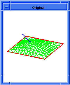  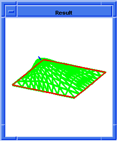
Figure. ds:set-load-gain |
[Top]
ds:set-pt-uv
- Action
-
Sets the parametric position within a deformable surface of a constraint
point, a pressure point, or a spring load.
Filename-
scm/scmext/ds/dsscm.cpp
APIs- api_dm_get_attrib_dm2acis
Syntax-
(ds:set-pt-uv owner tag uv-position)
Arg types-
Returns-
unspecified
Description
Sets the surface point location of a constraint point, a pressure point,
or a spring load in the face's deformable model. The tag identifier identifies
the tag object to modify. uv-position specifies the new parametric location
for the tag object. u and v values in uv-position are scaled
to range from 0.0 to 1.0.
- Arguments
-
owner ACIS face or edge on which the deformable model lives.
-
tag identifier identifies the tag object to modify.
-
uv-position specifies the new parametric location for the tag object.
; ds:set-pt-uv
; Set a constraint point's, pressure point's
; parametric position.
; Build a test square face with some tag objects.
; (6x6 control points, x and y side length = 36)
(define dsmodel1 (ds:test-face 6 6 36 36 0))
;; dsmodel1
; Do not display entity / ds test face exists.
(define erase (entity:erase dsmodel1))
;; erase
; Render the loads and constraints.
(ds:set-draw-state dsmodel1 1
(+ ds-draw-cstrns ds-draw-loads))
;; ()
; Add center point constraints.
(define cc1 (ds:add-pt-cstrn dsmodel1
1 "position" (par-pos 0.5 0.5)))
;; cc1
(ds:add-pt-cstrn dsmodel1 1 "position"
(par-pos 0 0))
;; 8
; Convert the edge constraints into edge loads.
(ds:crv-load-from-cstrn dsmodel1 3)
;; 9
(ds:crv-load-from-cstrn dsmodel1 4)
;; 10
(ds:crv-load-from-cstrn dsmodel1 5)
;; 11
(ds:crv-load-from-cstrn dsmodel1 6)
;; 12
(ds:set-pt-xyz dsmodel1 cc1 0
(position 18 18 36))
;; 8
(ds:solve dsmodel1 1 1)
;; ()
; OUTPUT Original
; Change the domain pt for the pt_constraint.
(ds:set-pt-uv dsmodel1 cc1 (par-pos 0.3 0.3))
;; 8
(ds:solve dsmodel1 1 1)
;; ()
; The surface moves through the constraint point
; which does not move. This is a lot like sliding
; a rubber sheet over a pointing finger.
; OUTPUT Result
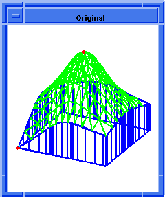  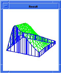
Figure. ds:set-pt-uv |
[Top]
ds:set-pt-xyz
- Action
-
Sets the position within xyz space of a control point, a constraint
point, or a spring load.
Filename-
scm/scmext/ds/dsscm.cpp
APIs- api_dm_get_attrib_dm2acis
Syntax-
(ds:set-pt-xyz owner tag point-index
{xyz-position | direction pick-event})
Arg types-
Returns-
integer
Description
Sets the three dimensional space point position for a control point,
a constraint point, or a spring load within the face's deformable model.
The tag identifier identifies the tag object to modify. The point can
be moved to an explicit location by specifying xyz-position.
Alternatively, the point can be moved towards a pick point by supplying
a direction and pick-event. When pick-event is supplied, a line is created
which runs through the pick point in the viewing direction. The tag object's
point is moved to approach the line. When direction = 1, the point is
moved in the x and y directions until it lies on the pick
line. When direction = 2, the point is moved in the z direction
to minimize its distance to the pick line.
When moving the tangent point on a point constraint and direction =
1, the tangent point is moved on a hemisphere centered on the base point.
The length of the point constraint's tangent vector does not change. When
moving that tangent point on a point constraint and direction = 2, the
tangent point is moved along the length of the tangent vector. The tangent
vector does not change its direction.
- The following are the point index values for the different tag
types:
point constraints
| point-index=0 |
modifies base-point |
| point-index=2 |
modifies curve tangent end-point |
| point-index=2 |
modifies surface tang1 end-point |
| point-index=3 |
modifies surface tang2 end-point |
| point-index=4 |
modifies normal vector end-point |
| point-index=5 |
modifies curve curvature |
end-point
| point-index=5 |
modifies surface curv1 end-point |
| point-index=6 |
modifies surface curv2 end-point |
| point-index=7 |
modifies curve binormal end-point |
vector loads
| point-index=0 |
modifies base-point |
| point-index=1 |
modifies tangent-point |
spring sets
| point-index= |
index of free-point to modify |
When the tag identifier recognizes a tag object, the deformable model
in the patch hierarchy which contains the tag object becomes the active
deformable model.
- Arguments
-
owner ACIS face or edge on which the deformable model lives.
-
tag identifier identifies the tag object to modify.
-
xyz-position an explicit location where point can be moved.
-
point-index index values for the different tag types.
-
direction is the direction of movement.
-
pick-event is supplied to create a line which runs through the pick
point in the viewing direction.
; ds:set-pt-xyz
; Sets a control point's, constraint point's or
; spring load's position within xyz space.
; Build a test square face with some tag objects.
; (6x6 control points, x and y side length = 36)
(define dsmodel1 (ds:test-face 6 6 36 36 0))
;; dsmodel1
; Do not display entity / ds test face exists.
(define erase (entity:erase dsmodel1))
;; erase
; Render the loads and constraints.
(ds:set-draw-state dsmodel1 1
(+ ds-draw-cstrns ds-draw-loads))
;; ()
; Add a point constraint.
(define cc1 (ds:add-pt-cstrn dsmodel1
1 "position" (par-pos 0.5 0.5)))
;; cc1
(ds:solve dsmodel1 1 1)
;; ()
; Track the constraint point with the mouse.
(ui:info-dialog
"click with the mouse to move the pt-cstrn :")
; click with the mouse to move the pt-cstrn :
;; #t
(ds:set-pt-xyz dsmodel1 cc1 0 2 (read-event))
;; 8
(ds:solve dsmodel1 1 1)
;; ()
; The constraint point moves in the z direction and
; the ds:solve call makes the surface track the
; point. |
[Top]
ds:set-tag-icon-grid
- Action
-
Sets the draw grid density single tag object icon.
Filename-
scm/scmext/ds/dsscm.cpp
APIs- api_dm_get_attrib_dm2acis
Syntax-
(ds:set-tag-icon-grid owner tag density)
Arg types-
Returns-
integer
Description
Using this Scheme extension, the icon draw grid density can be controlled
on a per-icon basis.
- Arguments
-
owner ACIS face or edge on which the deformable model lives.
-
tag is a unique specifier for a deformable modeling tag object, for example a
load or deformable model. Tags are generated upon tag object creation.
-
density is grid density.
; ds:set-tag-icon-grid
; build a sheet-body
(define my_sheet (sheet:face
(face:plane (position 0 -5 0) 10 10)))
;; my_sheet
; get the face
(define ds-model
(list-ref (entity:faces my_sheet) 0))
;; ds-model
; get a nice view
(iso)
;; #[view 852730]
(zoom-all)
;; #[view 852730]
; create a curve load
(define crv-load (ds:add-circ-load ds-model 2
(par-pos 0.5 0.5) (par-pos 0 .3) (par-pos .4 0)
1000))
;; crv-load
; change the icon gridding
(ds:set-tag-icon-grid ds-model crv-load 50)
;; 0 |
[Top]
ds:set-tag-icon-size
- Action
-
Sets the draw size for a single tag object icon.
Filename-
scm/scmext/ds/dsscm.cpp
APIs- api_dm_get_attrib_dm2acis
Syntax-
(ds:set-tag-icon-size owner tag size)
Arg types-
Returns-
integer
Description
Using this command, the icon draw size can be controlled on a per-icon
basis.
- Arguments
-
owner ACIS face or edge on which the deformable model lives.
-
tag identifier identifies the tag object to modify.
-
size is the draw size.
; ds:set-tag-icon-size
; build a sheet-body
(define my_sheet (sheet:face
(face:plane (position 0 -5 0) 10 10)))
;; my_sheet
; get the face
(define ds-model
(list-ref (entity:faces my_sheet) 0))
;; ds-model
; get a nice view
(iso)
;; #[view 852730]
(zoom-all)
;; #[view 852730]
; create a curve load
(define crv-load (ds:add-circ-load ds-model 2
(par-pos 0.5 0.5) (par-pos 0 .3) (par-pos .4 0)
1000))
;; crv-load
; change the icon size
(ds:set-tag-icon-size ds-model crv-load 4)
;; 0 |
[Top]
ds:set-tan-display-gain
- Action
-
Sets the display scaling value used to vary the visual length of all
the tangent constraints' tangent vectors.
Filename-
scm/scmext/ds/dsscm.cpp
APIs- api_dm_get_attrib_dm2acis
Syntax-
(ds:set-tan-display-gain owner target=1 [gain=1])
Arg types-
Returns-
unspecified
Description
Sets the display scaling value used to vary the displayed length of
all the tangent constraints' tangent vectors within the target deformable
models. The display gain's default value is 1.0. Use the
ds:set-comb-graphics
function to scale the curvature vectors.
- Arguments
-
owner ACIS face or edge on which the deformable model lives.
-
target specifies which deformable model to use in a patch hierarchy.
-
gain is a force of amplitude.
; ds:set-tan-display-gain
; Build a test edge with some tag objects.
; (6 control points, x side length = 36)
(define dsmodel1 (ds:test-edge 6 36 0))
;; dsmodel1
(define erase (entity:erase dsmodel1))
;; erase
; Do not render the edge.
; Add a position-tangent point constraint.
(define cl1 (ds:add-pt-cstrn dsmodel1 2
"pos_tan" (par-pos .5 .5)) )
;; cl1
; Render the loads, constraints, and curve
; normal-comb.
(ds:get-draw-state dsmodel1 1 )
;; 14
; Vary the tan_display_gain to change the image
; length of the constraint vector.
(ds:set-tan-display-gain dsmodel1 1 15.0)
;; ()
; Query the tan_display_gain.
(ds:get-tan-display-gain dsmodel1 1)
;; 15 |
[Top]
ds:set-tight-state
- Action
-
Sets whether a load/constraint on a deformable model is tightened.
Filename-
scm/scmext/ds/dsscm.cpp
APIs- api_dm_get_attrib_dm2acis
Syntax-
(ds:set-tight-state owner tag state)
Arg types-
Returns-
boolean
Description
Sets whether a load/constraint on a deformable model is tightened, overriding
a default shape of 1. There is no effect when the default shape is 0. This
extension returns a #t when the change is successful and #f when the change
is not successful.
- Arguments
-
owner ACIS face or edge on which the deformable model lives.
-
state is 1, the constraint is tightened; when state is 0, the constraint
is not tightened.
-
tag is the identifier for the load/constraint to modify. When the tag
identifier identifies a load/constraint, the deformable model in the patch
hierarchy which contains the load/constraint becomes the active deformable
model.
; ds:set-tight-state
; Build a test square spline face.
; (6x6 control points, x and y side length = 36)
(define dsmodel1 (ds:test-face 6 6 36 36 0))
;; dsmodel1
; Clear the face.
(define erase (entity:erase dsmodel1))
;; erase
(define refresh (view:refresh))
;; refresh
; Render the loads and constraints.
(ds:set-draw-state dsmodel1 1
(+ ds-draw-cstrns ds-draw-loads))
;; ()
; Make a curve constraint.
(define crv-cstrn (ds:add-str-cstrn dsmodel1 2 'p
(par-pos .2 .2) (par-pos .8 .8)))
;; crv-cstrn
; Turn off tightening.
(ds:set-tight-state dsmodel1 crv-cstrn 0)
;; #t
; Check the tight state - it should be 0.
(ds:get-tight-state dsmodel1 crv-cstrn)
;; 0
; Some operations automatically reset the tight state
; to 1 - curve tracking, for example.
(ds:make-tracking-curve dsmodel1 crv-cstrn)
;; 8
; We now have a tight state of 1.
(ds:get-tight-state dsmodel1 crv-cstrn)
;; 1 |
[Top]
ds:set-tracking-curve-target
- Action
-
Sets an xyz target curve for a curve constraint or curve load.
Filename-
scm/scmext/ds/dsscm.cpp
APIs- api_dm_get_attrib_dm2acis
Syntax-
(ds:set-tracking-curve-target owner tag
edge [reverse=0])
Arg types-
Returns-
integer
Description
Sets an xyz target curve for a curve load or curve constraint.
Curve constraints and loads attempt to adjust control points of a deformable
surface so that the image of a parameter (uv) curve within the surface
is pulled onto a target curve in xyz space. This command allows
the user to use an edge to specify the target curve geometry. By repeatedly
changing the edge's shape (or creating a sequence of new edges), calling
this routine, and then calling ds:solve
on the surface, the user can implement
"tracking curve" functionality, where the surface interactively changes
shape to track shape changes in the target curve. When the parameter curve
is not iso-parametric, Spatial recommends the use of curve loads (rather
than curve constraints) to prevent wrinkling of the surface. Wrinkles
in the surface can be traded off against gaps between the surface and
the target curve by adjusting the gain of the curve load.
If the reverse argument is 0, the target curve has the same direction as
the input edge; if 1 they are reversed relative to one another.
- Arguments
-
owner is a ACIS face or edge on which the deformable model lives.
-
tag is a unique specifier for a deformable modeling tag object, for example,
load or deformable model. Tags are generated upon tag object creation.
-
edge specifies the target curve geometry.
-
reverse specifies the direction of input edge.
; ds:set-tracking-curve-target
; Build a test square spline face
; 6x6 control points x and y side length = 36
(define dsmodel1 (ds:test-face 6 6 36 36 0))
;; dsmodel1
; Create a linear edge for tracking curve
(define edge (edge:linear (position 50 0 1)
(position 50 36 1)))
;; edge
(iso)
;; #[view 656874]
(zoom-all)
;; #[view 656874]
; Set the above created edge as the target
; for tracking curve
(ds:set-tracking-curve-target dsmodel1 4 edge)
;; 4
; Compute a new deformable position
(ds:solve dsmodel1 1)
;; () |
[Top]
ds:solve
- Action
-
Solves the deformable modeling equations to yield a new deformable
model shape for the deformable model.
Filename-
scm/scmext/ds/dsscm.cpp
APIs- api_dm_get_attrib_dm2acis
Syntax-
(ds:solve owner [target=1 iteration-count=1])
Arg types-
Returns-
unspecified
Description
Computes the optimal control-point positions for a deformable model
given the deformable model's current set of loads, constraints, and deformation
parameters using an optimization procedure. After generating a solution
for this deformable model, recursively generates a solve solution for
all of this deformable modeling's siblings and offspring. So a single
call to this function on the root of a hierarchy tree updates all of the
hierarchy's shapes. Alternatively, performance can be increased by calling
this function on one of the descendents of a deformable modeling hierarchy.
In this case solve will only be run on the passed in descendent and all
of its younger siblings, and all of their offspring. Older siblings and
ancestors will not be modified by such a call.
The state and parameter values of all of the deformable model's
constraints, loads, and deformation parameters affect the computation.
A change in any of these values will cause the shape of the deformable
model to change on the next subsequent call to ds:solve. The intended
use of the function is to act as part of the deformable modeling interaction
loop. The steps in this loop are defined below:
- Construct a shape model of a curve or surface.
- Construct a deformable model for the shape model.
- Add constraints and loads to the deformable model.
- Modify the parameters of the constraints, loads,
or deformation parameters.
- Call ds:solve to change the control-point positions
of the deformable model.
- Render the deformable model to see the change.
- Loop back to step 3 or 4 for interactive sculpting.
- When satisfied, commit the deformable model control-positions
back to the original shape model.
The iteration-count can be used to run solve on a deformable model more
than one time before returning. Calling ds:solve once with an iteration-count,
is more efficient than calling ds:solve iteration-count a
number of times in a row. The results remain the same.
For most of the deformable modeling package, a steady state solution
is found with one call to solve. This means a second call to solve will
not change the shape of the deformable model. Some features within the
package may require more than one call to solve before reaching a steady
state solution. These features include dynamics, pressure-loads, and
attractor loads which are all forces whose effects on the deformable model
depend on the shape of the deformable model.
When iteration-count is positive, solve will be run on the input deformable
model iteration-count number of times before returning.
When iteration-count is negative, solve will run repeatedly until a
steady state solution is achieved or until a maximum number of iterations
are computed. Steady state is achieved when the maximum motion of any
one control-point is less than the square root of DS_tolerance (equal
to SPAresabs in ACIS).
The maximum iteration count is set to DS_SOLVE_MAX_ITER_COUNT. If ds:solve
ever reaches DS_SOLVE_MAX_ITER_COUNT number of iterations, the package
assumes that a steady state solution is not possible and restores the
deformable model to the shape it had when entering this call and returns
an error code.
Calling ds:solve with iteration-count == -1 when not using pressures,
attractors, or dynamics will slow the system down. The package will execute
two solves before it discovers that it achieved steady state in one iteration.
- The target argument specifies which deformable model to use in
a patch hierarchy. Valid values for target are:
-
1= active deformable model
-
2= root deformable model
-
-1= active deformable model and offspring
-
-2= root deformable model and offspring
-
Otherwise, the target is the deformable model whose tag identifier
equals target.
- Arguments
-
owner is a ACIS face or edge on which the deformable model lives.
-
target specifies which deformable model to use in a patch hierarchy.
-
iteration-count can be used to run solve on a deformable model more
than one time before returning.
; ds:solve
; Solves the deformable modeling equations to yield
; a new deformable model shape.
; Build a test square face with some tag objects.
; (6x6 control points, x and y side length = 36)
(define dsmodel1 (ds:test-face 6 6 36 36 0))
;; dsmodel1
; Do not display entity / ds test face exists.
(define erase (entity:erase dsmodel1))
;; erase
; Render the loads and constraints.
(ds:set-draw-state dsmodel1 1
(+ ds-draw-cstrns ds-draw-loads))
;; ()
; Add a point constraint.
(define cc1 (ds:add-pt-cstrn dsmodel1
1 "position" (par-pos 0.5 0.5)))
;; cc1
(ds:solve dsmodel1 1 1)
;; ()
; The system should not move since the constraint
; was added to an equilibrium position.
; Change the constraint point's 3 space position.
(ds:set-pt-xyz dsmodel1 cc1 0
(position 18 18 15))
;; 8
; Solve for the new equilibrium position.
(ds:solve dsmodel1 1 1)
;; ()
; The surface changes its' shape to interpolate
; the point.
|
[Top]
ds:split-domain
- Action
-
Splits the existing deformable model elements.
Filename-
scm/scmext/ds/dsscm.cpp
APIs- api_dm_get_attrib_dm2acis
Syntax-
(ds:split-domain owner target=1 uv-pos-list)
Arg types-
Returns-
unspecified
Description
Uses the uv-pos to split the domain description of the target deformable
model. This splits the existing target deformable model elements. When
working with B-splines, this is accomplished by inserting new knot locations.
- The target argument specifies which deformable model to use in
a patch hierarchy. Valid values for target are:
-
1= active deformable model
-
2= root deformable model
-
-1= active deformable model and offspring
-
-2= root deformable model and offspring
-
Otherwise, the target is the deformable model whose tag identifier
equals target.
The function splits the model using the first par-pos and then splits
that result with the next point on the uv-pos-list and so on until all
the uv-pos-list points have been used.
Subdividing the domain description splits the deformable model's elements
and increases the number of degrees of freedom in the model. This is done
for B-splines by inserting new knot locations. The surface will be able
to bend into more interesting and detailed shapes, but the solution times
will increase. The u and v values in uv-pos are scaled to
range from 0.0 to 1.0. Deformable curves only use the u values
of the input par-pos objects.
- Arguments
-
owner is a ACIS face or edge on which the deformable model lives.
-
target specifies which deformable model to use in a patch hierarchy.
-
uv-pos-list is a list of points which are used for splitting function.
Limitations-
Avoid splitting domain at existing knot values.
; ds:split-domain
; Split existing deformable model elements.
; create a single span B-spline face and use this
; function to increase the number of spans and
; elements. Make a single span test face.
; (4x4 control points, x and y side length = 36,
; u and v direction degrees = 1)
(define dsmodel1 (ds:test-face 4 4 36 36 0))
;; dsmodel1
; Do not display entity / ds test face exists.
(define erase (entity:erase dsmodel1))
;; erase
; Render the loads and constraints.
(ds:set-draw-state dsmodel1 1
(+ ds-draw-cstrns ds-draw-loads))
;; ()
; Render its control points.
(ds:set-draw-state dsmodel1 1 ds-draw-cpts)
;; ()
(ds:split-domain dsmodel1 1 (par-pos 0.5 0.5))
;; ()
; The face now renders with 25 (5x5) control points.
; Use the ds:debug command to examine the changes of
; ds:split-domain. |
[Top]
ds:start-adm
- Action
-
This extension starts adm on the given entity using the given options.
Filename-
scm/scmext/ds/dsscm.cpp
APIs-
api_dm_get_attrib_dm2acis,
api_dm_query_attrib_dm2acis
Syntax-
(ds:start-adm entity [adm-options] [acis-opts])
Arg types-
Returns-
boolean
Description
This extension starts adm on the given entity using the given options.
The values are TRUE if options applied, FALSE if adm is already started
on entity. This allows the use of legacy algorithms in subsequent adm
operations.
- Arguments
-
entity is the given input entity.
-
adm-options is a different adm options available. TRUE if options applied
and FALSE otherwise.
-
acis-opts contains journaling and versioning information.
; ds:start-adm
; Create a block
(define b1 (solid:block
(position 5 10 15) (position 10 20 30)))
;; b1
; define adm options
(define admo
(ds:adm-options "trim_faces" 0
"use_boundary_loads" 0))
;; admo
; define Acis Options
(define v (versiontag 7 0 0))
;; v
(define ao (acisoptions:set "version" v))
;; ao
; pick a face
(ray:queue 8.00781 14.6484 500 0 0 -1 1)
;; #[ray (8.00781 14.6484 500) (0 0 -1)]
(define ds-model (pick-face))
;; ds-model
; start adm
(ds:start-adm ds-model admo ao)
;; #t |
[Top]
ds:test-edge
- Action
-
Creates simple spline edges for testing.
Filename-
scm/scmext/ds/dsscm.cpp
APIs-
None
Syntax-
(ds:test-edge controlpt-count [size-x=36 [size-z=0.0
[curve-degree=3 [x0=0 [u-min=0 [u-max=1]]]]]])
Arg types-
Returns-
edge
Description
Constructs and returns a spline edge suitable for testing.
- Arguments
-
controlpt-count specifies the number of control points.
-
size-x specifies the extent of the edge in three dimensional space.
It becomes a line starting at (x=0, y=0) and stopping at the point (x
= x0+size-x, y=0). The default is 36.0.
-
size-z is 0 (default) to build a flat line in the z = 1 and y = 0
planes. The z dimension is built about z = 1 plus an arbitrary displacement
guaranteed not to exceed size-z, which defaults to 0.0.
-
curve-degree specifies the degree of the curve. The default degree
value is 3.
-
u-min and u-max specify the domain range of the edge. The default domain
range is from 0.0 to 1.0.
; ds:test-edge
; Add to a square test face a parabolic crv-load
; and use it.
; Build a test spline edge
; (6x6 control points, x and y side length = 36)
(define dsmodel1
(ds:test-edge 6 36 0 0 3 0.0 0.0 1.0))
;; dsmodel1
; This returns a spline edge having 6 control points. ; The x side has
a length of 36, degree of 3, and
; domain and range of 0 to 1. |
[Top]
ds:test-face
- Action
-
Creates simple spline faces for testing DM functions.
Filename-
scm/scmext/ds/dsscm.cpp
APIs-
None
Syntax-
(ds:test-face ucont-pt-count vcont-pt-count
[size-x=36 [size-y=36 [size-z=0 [rational=0
[degree-u=3 [degree-v=3 [x0=0 [y0=0
[u-min=0 [v-min=0 [u-max=1 [v-max=1]]]]]]]]]]]])
Arg types-
Returns-
face
Description
Constructs and returns a spline face suitable for testing deformable
modeling extensions.
- Arguments
-
ucont-pt-count and vcont-pt-count specify the number of control points
in the u and v directions.
-
size-x and size-y (which default to 36.0), and x0 and y0 (which default
to 0), specify the extent of the face in three dimensional space. The
face is a square starting at (x0, y0) and stopping at the point (x, y)
= (x0+size-x, y0+size-y).
-
size-z specified as 0 (default) builds a flat on the z=1 plane. The z-dimension
is built about z=1, plus an arbitrary displacement guaranteed not
to exceed size-z, which defaults to 0.0.
-
degree-u and degree-v specify the degree of the surface in the u
and v directions. The default degree value is 3.
-
rational specified as 0 (default), returns a NUB; otherwise, when specified as 1, returns a NURB.
-
u-min, u-max, v-min, and v-max specify the domain range of the returned
surface. The default domain range is [0,1,0,1]: the unit square.
; ds:test-face
; Build a simple spline face for testing the
; function.
; Build a test square spline face.
(define dsmodel1 (ds:test-face 6 6 36 36 0 3 3))
;; dsmodel1
; Returns a spline face.
; (6x6 control points, x and y side length = 36,
; u and v direction degrees = 3) |
[Top]
ds:test-scatter
- Action
-
Creates a list of randomly generated positions sampled from a simple
trigonometric function.
Filename-
scm/scmext/ds/dsscm.cpp
APIs-
None
Syntax-
(ds:test-scatter point-count x-size y-size z-size)
Arg types-
Returns-
unspecified
- Arguments
-
point-count is the count of points. This extension makes a list of
randomly generated positions sampled from a simple trigonometric function.
This function is only a convenience for making test cases to be used in
the construction of deformable surface spring set loads.
-
The x and y position coordinates are sampled from the sets:
-
0 ≤ x ≤ x-size, 0 ≤ y ≤ y-size
-
And z = sin(2Pi*x/x-size) * sin(4Pi*y/y-size) * z-size + 1.0 ;
; ds:test-scatter
; Example command for demonstrating how a deformable
; model can be used to generate a surface shape
; from a set of scattered points.
; Build a test square spline face.
; (12x12 control points, x and y side length = 36)
(ds:test-scatter 10 36 36 5)
; A list of positions with
; 0 <= x <= 36
; 0 <= y <= 36
; z = sin(2*PI*x/36) * sin(4*PI*y/36) * 5 + 1.0
;; (#[position 0 0 1] #[position 0 36 1]
;; #[position 36 0 1] #[position 36 36 1]
;; #[position 0.0150151066621906 6.76302377391888
;; 1.0092231001733] #[position 2.31965086825159
;; 21.7048860133671 2.8940602436359]
;; #[position 7.02011169774468 29.758476516007
;; -2.86161625043141] #[position 16.203497421186
;; 10.7515488143559 0.114757902363361]
;; #[position 21.874080629902 20.9592577898495
;; -1.68726313486233] #[position 14.0892971587268
;; 34.3073213904233 -0.756925421091428]
;; #[position 32.5260170293283 6.16241950743126
;; -1.38283601576729] #[position 27.6479384746849
;; 12.1798150578326 5.44980949280219]
;; #[position 25.0968352305673 28.3734244819483
;; 3.18023783615772] #[position 5.30326242866298
;; 5.97235023041475 4.47879354664393]) |
[Top]
ds:toggle-cstrn
- Action
-
Enables and disables a point, curve, or area constraint to an enabled
or disabled state.
Filename-
scm/scmext/ds/dsscm.cpp
APIs- api_dm_get_attrib_dm2acis
Syntax-
(ds:toggle-cstrn owner tag)
Arg types-
Returns-
integer
Description
Toggles the state of the constraint specified by tag in the face's deformable
surface between enabled and disabled. Disabled constraints move as the
surface is deformed. Enabled constraints force the surface to interpolate
their current positions as the surface is deformed.
When the tag identifier recognizes a constraint, the deformable model
in the patch hierarchy which contains the constraint becomes the active
deformable model. Returns a tag identifier.
- Arguments
-
owner is the face or edge being deformed.
-
tag specifies the state of the constraint.
; ds:toggle-cstrn
; Toggle a point or curve constraint between enabled
; and disabled states.
; Build a test square face with some tag objects
; (6x6 control points, x and y side length = 36)
(define dsmodel1 (ds:test-face 6 6 36 36 0))
;; dsmodel1
; Do not display entity / ds test face exists.
(define erase (entity:erase dsmodel1))
;; erase
; Render the loads and constraints.
(ds:set-draw-state dsmodel1 1
(+ ds-draw-cstrns ds-draw-loads))
;; ()
; Add a set of point constraints.
(define cc1 (ds:add-pt-cstrn dsmodel1
1 "position" (par-pos 0.5 0.5)))
;; cc1
(ds:add-pt-cstrn dsmodel1 1 "p" (par-pos 0.0 0.0))
;; 8
(ds:add-pt-cstrn dsmodel1 1 "p" (par-pos 0.0 1.0))
;; 9
(ds:add-pt-cstrn dsmodel1 1 "p" (par-pos 1.0 1.0))
;; 10
(ds:add-pt-cstrn dsmodel1 1 "p" (par-pos 1.0 0.0))
;; 11
(ds:set-pt-xyz dsmodel1 cc1 0 (position 18 18 15))
;; 8
(ds:solve dsmodel1 1 1)
;; ()
; OUTPUT Original
; The surface deforms while preserving the 4
; edge constraints.
; Toggle the edge constraints and solve.
(ds:toggle-cstrn dsmodel1 1)
;; 0
(ds:toggle-cstrn dsmodel1 2)
;; 0
(ds:toggle-cstrn dsmodel1 3)
;; 6
(ds:toggle-cstrn dsmodel1 4)
;; 6
(ds:solve dsmodel1 1 1)
;; ()
; The square now deforms along the edges.
; Toggle the edge constraints, move the constraint
; point and solve.
(ds:toggle-cstrn dsmodel1 1)
;; 0
(ds:toggle-cstrn dsmodel1 2)
;; 0
(ds:toggle-cstrn dsmodel1 3)
;; 6
(ds:toggle-cstrn dsmodel1 4)
;; 6
(ds:set-pt-xyz dsmodel1 cc1 0 (position 18 18 1))
;; 8
(ds:solve dsmodel1 1 1)
;; ()
; The surface deforms bringing the center back
; near its starting place but the edge curve
; constraints are left arching into the heights.
; OUTPUT Result
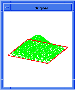  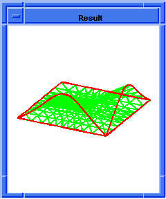
Figure. ds:toggle-cstrn |
[Top]
ds:toggle-seam
- Action
-
Sets the seam and link connections of a patch to a C0 (position) or
a C1 (position and tangent) constraint.
Filename-
scm/scmext/ds/dsscm.cpp
APIs- api_dm_get_attrib_dm2acis
Syntax-
(ds:toggle-seam owner target=1)
Arg types-
Returns-
integer
Description
Toggles the seam and link connectivity properties of a patch. It changes
the value of the curve constraints which stitch a patch between being
a C0 (position only) and C1 (position and tangent), and a C2 (position,
tangent, and curvature) connection.
- Arguments
-
owner is a ACIS face or edge on which the deformable model lives.
-
target argument specifies which deformable model to use in a patch
hierarchy. Valid values for target are:
-
1= active deformable model
-
2= root deformable model
-
-1= active deformable model and offspring
-
-2= root deformable model and offspring
-
Otherwise, the target is the deformable model whose tag identifier
equals target.
; ds:toggle-seam
; Add to a square test face a parabolic crv-load
; and use it.
; Build a test square spline face.
; (6x6 control points, x and y side length = 36)
(define dsmodel1 (ds:test-face 6 6 36 36 0))
;; dsmodel1
; Do not display entity / ds test face exists.
(define erase (entity:erase dsmodel1))
;; erase
; Render the loads and constraints.
(ds:set-draw-state dsmodel1 2
(+ ds-draw-cstrns ds-draw-loads))
;; ()
; Add a pt-cstrn at the center of the parent and
; track it.
(define cc1 (ds:add-pt-cstrn dsmodel1
2 "position" (par-pos 0.5 0.5)))
;; cc1
(ds:set-pt-xyz dsmodel1 cc1 0
(position 18 18 10))
;; 8
; Compute a new deformable model position.
(ds:solve dsmodel1 2 1)
;; ()
; set default shape & remove point constraint
(ds:set-default-shape dsmodel1 2 1)
;; ()
(ds:rm-tag-object dsmodel1 cc1)
;; 8
; Add a rectangular patch to the parent shape.
; This defaults to C1 connection and becomes
; the active shape.
(define patch1 (ds:add-patch dsmodel1 2 1
(par-pos 0.2 0.2) (par-pos 0.8 0.8)
(par-pos 0 0)3))
;; patch1
; Add and track a point constraint on the patch.
(define cc2 (ds:add-pt-cstrn dsmodel1
1 "position" (par-pos 0.5 0.5)))
;; cc2
(ds:set-pt-xyz dsmodel1 cc2 0
(position 18 18 36))
;; 8
(ds:solve dsmodel1 patch1 1)
;; ()
; Toggle the connectivity of the patch to its parent.
; Toggle twice to make C0
(ds:toggle-seam dsmodel1 patch1)
;; ()
(ds:toggle-seam dsmodel1 patch1)
;; ()
(ds:solve dsmode11 2 1)
;; ()
; The shape changes along the seam. |
[Top]
ds:use-link-cstrns
- Action
-
Overrides the use of link loads in favor of link constraints in the
current DM session.
Filename-
scm/scmext/ds/dsscm.cpp
APIs- api_dm_use_link_cstrns
Syntax-
(ds:use-link-cstrns)
Arg types-
Returns-
unspecified
Description
Sets the deformable modeling session to override the use of link loads
in favor of link constraints. This returns the user to pre-relase 6.2
behavior. This function should ONLY be called at the start of the DM session.
This is a temporary function and is removed from the ADM interface at
the same time as link constraints.
; ds:use-link-cstrns
; Example not available at this time.
(ds:use-link-cstrns)
;; ()
|
[Top]
vertex:from-position
- Action
-
Makes an isolated vertex from the given position.
Filename-
scm/scmext/ds/acovr_scm.cpp
APIs-
None
Syntax-
(vertex:from-position pos)
Arg types-
Returns-
Isolated vertex
Description
Makes an isolated vertex from the given position.
- Arguments
-
pos is the input position.
;vertex:from-position
; Create Isolated vertex
(vertex:from-position (position 0 0 0))
;; #[entity 1 1] |
[Top]
© 1989-2007 Spatial Corp., a Dassault Systèmes company. All rights reserved.

![]()


