ACIS Deformable Modeling
The ACIS Deformable Modeling Component (ADM), in the adm directory, provides interactive sculpting of free-form surfaces and curves. ADM supplements traditional control point manipulation techniques.
Shape and shape features may be sculpted within larger shapes without changing the larger shape beyond a local bound by using local deformations. For example, after completing the design shape of a car door, a designer may want to insert a localized relief to make room for a flush door handle without changing the line of the car body. The shape of the relief feature is a local deformation to the car door.
Deformable modeling uses a simulation of an elastic curve or surface that mimics real-world behavior to change the shape being designed. The resulting free-form curves and surfaces are fair and easy to manipulate. Users may make small deformations from an existing shape or very large deformations to create an entirely new shape. The phrase deformable model refers specifically to a deformable curve or surface.
Deformable modeling uses an energybased optimization strategy which minimizes the energy stored due to bending and stretching, so the shape that a deformable curve adopts is the one shape out of all possible shapes that minimizes the internal energy of the curve. This algorithm automatically produces very fair shapes similar to those seen in the billowing of a sail or the clean line of a bending beam.
Deformable modeling is a more powerful alternative to control point manipulation and skinning. Control point manipulation can change a free-form shape interactively, but not while enforcing constraints. Skinning can build surfaces that satisfy several constraints but do not allow the shapes to be sculpted. With deformable modeling, users can sculpt shapes which only deform to be fair while simultaneously satisfying a very rich set of constraints.
The deformable modeling algorithm is an operator and not a representation. It does not require any particular curve or surface representation. Editing for B-spline and NURB curves and surfaces is supported.
The phrase deformable model refers to a deformable curve or surface.
Topics include:
- The Sculpting Process
- Types of Deformations
- Loads
- Converting Between Loads and Constraints
- Constraints
- Default Shapes
- Parameters
- Tag Objects
- Parametric Positions
- Interfaces
- Limitations
The Sculpting Process
The sculpting session consists of adding and manipulating any number and combination of loads and constraints to a deformable curve or surface. Loads and constraints have parameters that affect the overall shape of the deformable model in a predictable manner. Load and constraint parameters may be bound to the mouse location and updated repeatedly, creating an interactive sculpting environment.
The sculpting options include loads, constraints, local deformations, default shapes, and surface parameters.
A sequence for a typical sculpting session consists of the following steps:
- Select a face or edge to be sculpted,
- Apply sculpting options to affect the deformable shape,
- Ask the system to solve for a new shape and display the result,
- Repeatedly modify load and constraint parameter values, solve, and display.
- Once a desired shape is found, commit it to the face or edge. Or, if desired, restore the original face or edge shape.
In addition, understanding how to use the default shape feature, parameters, tag objects, and parametric positions can further refine the modeling process.
To enable an interactive sculpting package, ADM has been designed to minimize the update time of a basic modify, compute, and render loop. Executing this loop fast enough to run as an interactive animation creates the look and feel of interactive sculpting. Interactive sculpting is achieved when the manipulation of the load and constraint parameters are tied to the mouse so that for each mouse move event there is a modify, compute, and render loop.
ADM is designed to support two typical user scenarios for editing free-form curves and surfaces: the edit sheet and the edit solid face scenarios.
In the edit sheet scenario, the user starts by selecting a sheet face or a wire edge to edit. When a sheet face is selected, an ADM model of the sheet is made and it appears on the screen as a normal light shaded face. Each of the boundaries of the original sheet are automatically converted into curve constraints which are shown as red curves drawn within the surface. The user adds and manipulates loads and additional constraints until the surface is sculpted into a desired shape. Graphic icons for each load and constraint appear; loads are shown in blue and constraints in red. During the sculpting session of a sheet surface, the user may disable the faces boundary curve constraints so the boundaries of the sheet may be manipulated. Disabled constraints are shown in magenta. The sculpted shape can be saved by committing it to the geometry kernels model, at which time the original faces geometric description is backed up for roll back and then updated. Additionally, all face boundaries whose geometry have also been edited are similarly backed up and updated.
The edit a solid face scenario differs from the edit sheet scenario in that the user begins by selecting a face within a valid solid model. The face is automatically converted into a spline of a high enough degree and with enough control points so it can be reasonably sculpted. During the sculpting session, the user may not disable the boundary curve constraints. Preserving these constraints guarantees that the shape of the face continues to fit within the solid model after the sculpting has been completed. When the sculpted shape is committed back to the kernel geometry model, only the geometry of the face is updated, since the boundary curve shapes have been preserved.
Types of Deformations
Deformations can be local or isolated, depending on whether their boundaries are generated using patches or zones. Both surfaces and curves may be deformed.
Local Deformations
Local deformations use hierarchical patches. A patch defines a local area of the surface where deformations are applied. A child patch can be applied to any deformable curve or surface. Once applied, the patch is also a deformable curve or surface with all associated capabilities. A child patch can own a child patch (grandchild).
Deformations made to the child do not affect the shape of the parent. Deformations of the parent change the shape of the child so that the child continues to stay attached to the parent curve. The childs attachment to its parent is enforced by using the point constraint mechanism. A child patch is totally contained by its single parent, which prevents child patches from spanning across link constraints.
Any deformable surface or curve can contain any number of child patches. Each child patch is attached to its parent through a seam, similar to a seam in sewing that joins two pieces of fabric. A seam is one or more curves that connect together to form a simple closed loop. The child patch connects to its parent patch along the seam with C0 (position) or C1 (position and tangent) continuity.
The shape of each child patch on a surface is a rectangle large enough to contain its seam. The child patchs shape outside the seam is trimmed away, allowing the boundary of the patch to form any shape. The final curve or surface shape is defined by the child patch for locations within the seam boundary. For locations outside the seam, the final curve or surface shape is defined by the parent.
On a curve, a patch is a second curve which is attached to its parents at its end points and is defined over a subset of the parents domain space. The actual curve, as seen by the user, is really a composite curve, defined by the parent curve outside the patch region and defined by the child patch within the patch region. A child patch may attach to its parent with either C0 (position only) or C1 (position and tangent) continuity. C0 patches allow a curve with corners to be defined, and C1 patches make smooth composite curves.
Isolated Deformations
Isolated deformations use the fixed/deformable zones approach. They are more limited than patches, but provide similar results. A zone is a sub-region of a deformable modeling shape and is specified as a separate shape within the domain space of the shape. A deformation zone has an inside and outside.
Isolated deformations are implemented by the area constraint which is represented by the DS_area_cstrn object. A DS_area_cstrn object partitions the shape being constrained into fixed or deformable zones. The shape of the area constraints zone is limited to domain space rectangles only. The deformation is limited to those elements of the deformable modeling shape which lie completely within the boundaries of the area constraints zone.
The constructor to the area constraint requires a zone and a zone_flag. The zone_flag defines the region of the zone (inside or outside) to be made deformable.
The area constraint also partitions the degrees of freedom (dofs) of the deformable modeling shape into free and fixed sets. During the course of a deformation only free degrees of freedom move. Multiple area constraints are treated by taking the union of all the free areas.
The area constraint works seamlessly with all other deformable modeling loads and constraints.
The continuity between a deformable and a fixed zone is determined by the continuity across the element boundaries. For example, a bi-cubic B-spline with single knot internal values always supports C2 continuity between the two zones. If extra knots are added to the knot boundary, C1 or C0 continuity across the zone boundaries is supported.
Deforming Surfaces
A set of surfaces being sculpted simultaneously is called a deformable modeling mesh. The individual surfaces within the deformable modeling mesh are connected to one another by link curve constraints. Within the deformable modeling mesh, each surface is equivalent to a FACE and each link constraint is equivalent to an EDGE in a boundary representation model.
Multi-surface deformable modeling is implemented by simultaneously solving the single-surface deformable modeling equations for each surface in the mesh. The figure below shows how two surfaces are combined into a single deformable modeling mesh by the existence of a link constraint (shown in red). Either C1 or C0 continuity between each surface patch can be enforced as the patches are deformed.
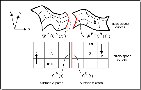
Figure. A Multi-surface Deformation Mesh
Tolerant hot deformable modeling makes link loads and trim curve multi-surfaces possible in ADM. Tolerant hot models allow gaps in geometry, which become curve constraint/load gaps in ADM.
Before committing to ACIS, a deformable models boundary constraint source geometry replaces the ACIS pcurve geometry. For links, the edge geometry is also replaced. The new edge/coedge complex is checked using api_check_edge_errors with a tolerance of SPAresabs, and, as required, edges are marked as tolerant. The SVD (singular value decomposition algorithm) refinement step is not applied as part of the commit process.
Deforming Curves
The following figure illustrates deformable curve modeling. This sample curve is defined by interpolating four constraint points (shown as magenta squares). The curve is deformed by moving one of the interior constraint points through a sequence of positions. The curves control points are shown (as blue dots) for the first and last shape in the sequence. In this example, moving one constraint point drives the deformable modeling algorithm, which moves all the control points to continue interpolating all the constraint points and to keep the curve fair. Any number of point constraints can be added to a curve placed at any position on the curve.
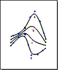
Figure. Deformable Curve
The following figure illustrates the default shape feature for deformable curves. The initial curve a is a simple figure eight. This shape is captured as the curves default shape. Two end constraint points are added to the curve. Curve shapes b and c are made by pulling the upper point constraint towards the lower left corner. The default shape feature ensures that the curve loops twice between the two endpoints no matter where those endpoints move in space.
The shape that a deformable curve adopts is the one shape out of all possible shapes that minimizes the internal energy of the curve.
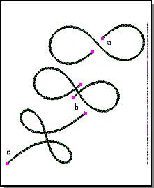
Figure. Default Shape
Loads
Loads pull or push deformable models to approximate locations and are presented in the form of everyday physical loads. The current set of loads includes:
- Pressures
- Puff (push) curve and surface shapes. Apply to single points or entire regions with a deformable model.
- Springs
- Pull curve and surface shapes. Acts between a point in space to a point in a deformable curve or surface.
- Vector
- Like gravity, draws an entire body in a single direction. Acts on the entire body of a deformable model.
- Link Curve
- Uses a quadratic (i.e., spring) energy penalty to enforce continuity between surfaces, rather than enforcing an exact constraint.
- Attractor
- Draws or repels a body from a single point. Acts on the entire body of a deformable model.
Users can add loads to deformable curves and surfaces. Each load behaves as a function that acts over the entire domain area of the deformable model. For spring loads, this function is zero except at one or a few specified points. For curve loads, this function is zero everywhere except over one curve within the surface. For vector and attractor loads, this function is never zero; these loads affect every point on the deformable surface.
Pressures
To use pressure loads effectively, the user must be aware of two pressure behaviors.
-
The effect a pressure load has on a surface is a function of the surfaces
stiffness. Surfaces with lots of curve and point constraints are stiffer than
surfaces without constraints. A good strategy for finding appropriate pressure
gains is to start all pressure loads with a gain of 0, then increase the gain
to 1 and solve. If the load has no visible effect on surface shape, increase
the load to 10 and try again. Very quickly a pressure magnitude is found that
moves the surface. Surfaces which require pressure gains of .1 to 10000 are not
uncommon. Linear variations in pressure gain can be used to sculpt the surface
once you have identified the right order of magnitude for the gain.
- Using pressure loads by themselves to deform a shape a very large distance from its initial shape may cause the overall structure to wobble. That is, after each solution of the deformable modeling equation, the system may move to a new equilibrium position. Effective use of the pressure load is in combination with position constraints for modest sized deformations about a default shape. As a general rule of thumb, use pressures to modify surface shape modestly, and use tracked point constraints, spring loads, and curve loads to change the shape of a surface dramatically.
One strategy for using pressures to make large deformations is to break up one large deformation into a series of smaller deformations with the use of the default shape. To make a large pressure deformation, begin with a single small deformation due to pressure. Capture this shape as the default shape (for example, with the DML function DM_set_default_shape). Use additional pressure to continue growing the shape. After another modest deformation capture another default shape and so on. Very large deformations due to pressure effects can be achieved in this fashion.
Point Pressure Load
A point pressure load is firmly fixed at one location of a deformable surface and applies a force that always acts normal to the surface. The forces gain or its location in the surface can be altered. Surfaces tend to bend in the direction of the point pressure when the pressures gain is increased. Gain values may be positive or negative. Positive gains puff surface shapes, while negative gains suck them. Point pressures on deformable curves act in the curves bi-normal direction.
Deformable modeling and pressure load can be used to support a puff operator which inflates a face. Different amounts of puff can be tried by varying the amplitude of the pressure load. The puff operator is an example of user leverage. A user can coordinate the movement of all the control point locations of a free-form shape by manipulating a single number, the pressure loads amplitude.
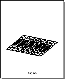
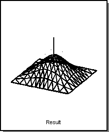
Figure. Point Pressure Gain
Distributed Pressure Load
A distributed pressure is a normal force applied to a continuous subregion of a deformable model. Increasing the gain of a distributed pressure applied to a deformable surface tends to make the surface bellow. The domain of the distributed pressure can be limited so that it only acts on a portion of a surface. With this capability, multiple independent distributed pressures can be added to a deformable model. For example, in constructing a goblet from a periodic face, a positive pressure can be used at the top of the surface to create the goblets bowl, while a negative pressure can be used at the bottom of the surface to slim down the goblets base.
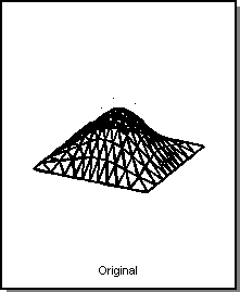
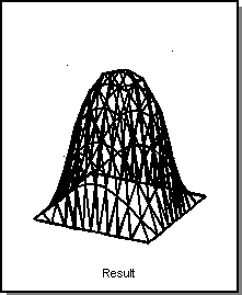
Figure. Distributed Pressure (Puff)
Springs
For curves, an effective load is the spring load. It is a force that acts from one point on the curve to one point in free space. Springs act to pull a point on the curve towards a point in space. A good application for springs is to force a curve to lie near a set of data points; perhaps collected by tracking the mouse.
Users can sculpt the shape of the curve by changing the free end position of the spring at runtime. As the free end position of the spring is moved, the curve deforms to stay near the moving point. An interface which can set the free end position repeatedly by tracking the mouse can animate the sculpting.
Point Spring Load
A point spring load is a point force acting between one point on a deformable model and another free point located somewhere in three dimensional space (for example, an xyz point). Like a real spring, a point spring acts to pull the point on the deformable model closer to the point in three dimensional space. The further the two points are apart from one another, the larger the force of the pull. The stiffness of the spring may be increased, causing the deformable model point to come closer to the free point; or the free point may be moved to a new location, causing the deformable model to approximately track the free point location.
Note: Forcing a deformable model to interpolate a point location is supported through point constraints.
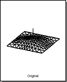 <
< 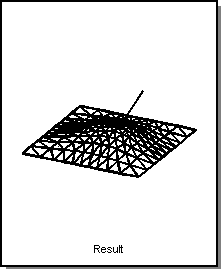
Figure. Point Spring
Curve Spring Load
A curve spring load is the generalization of a point spring to a curve. While a point spring is a single line of force that connects two points, a curve spring is a sheet of force that connects two curves. Curve spring loads cause a curve within a deformable surface to approximate the shape of a curve in space. Using the goblet example, the initial shape of the goblet along its top and bottom edges can be created by connecting curve springs between those edges and circles in three dimensional space. The spring curves act to wrap the deformable surface around the circles just like a shower curtain tracks its curtain rod. (Forcing a surface to interpolate all the points within a curve is supported through curve constraints.)
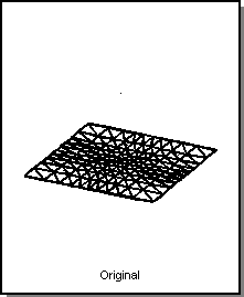
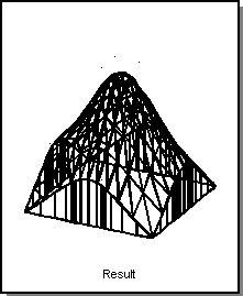
Figure. Curve Spring
Curve Loads
Curve loads are applied to deformable surfaces to restrict the shape of a surface at all the points within the curve load domain. Curve loads can be used to restrict position, to restrict the surface tangent in a direction perpendicular to the curve load, and to restrict surface curvature in a direction perpendicular to the curve load.
Curve constraints and curve loads share the same underlying implementation. This means that any routine that can be called on a curve constraint (such as ATTRIB_DM2ACIS::Set_cstrn_behavior) can also be called on a curve load. Curve loads can affect surface tangents and curvatures and be tracked.
Tracking curve loads are the recommended method for implementing trim curve tracking. By using ATTRIB_DM2ACIS::Set_tracking_curve_target, users can explicitly specify a spline target for the position, tangent, or curvature of a (tracking) curve constraint or load. It takes a target bs3curve and an integer flag indicating whether the position, tangent, or curvature target is being specified.
Link Curve Loads
Link curve loads are replacing link constraints in ADM. A link curve load uses a quadratic (that is, spring) energy penalty to enforce continuity between surfaces, rather than enforcing an exact constraint. All functions that act upon link constraints can act upon link curve loads. Link curve loads are automatically added by ADM in the same situations in which link constraints were added in earlier releases; users need take no special action to take advantage of their availability.
Link curve loads differ from link constraints in the following ways:
-
Link curve loads return a
DS_TAGS type of DS_tag_link_load, as opposed to DS_tag_link_cstrn
for link constraints; user code that switches on this value will need to be
adjusted.
-
Link curve loads enforce locally rotated C1 and C2 continuity when tangent or
curvature linked behaviors are turned on. This defines a cross tangent
derivative to a curve on a surface as the parametric (uv) directional
derivative that produces a unit (xyz) vector perpendicular to the curve.
Locally rotated C1 continuity enforces equality between the first cross tangent
derivatives on the two surfaces; locally rotated C2 continuity enforces
equality between the second cross tangent derivatives. This has the advantage
that imposing C1 continuity across a link that is already G1 will not force the
surfaces to move; the strict C1 imposed by link constraints can cause large
movements of such surfaces.
-
Link curve loads are not constrained to isoparametric boundaries only; links
between arbitrary trim curves are allowed.
- Link curve loads have an associated gain (accessed through ATTRIB_DM2ACIS methods Set_load_gain and Get_load_gain) that can be used to trade off between gap size and surface wrinkling.
The locally rotated continuity is shape dependent. The parametric direction vector used in the cross tangent derivative is calculated using the surface shape when the behavior is turned on. If state reproducibility is desired (i.e., the same solution is obtained given a particular set of loads and constraints), then the user should set the default shape (this is a state changing event that must be logged) immediately before turning on these behaviors.
The default use of link curve loads can be overridden in favor of link constraints by calling api_dm_use_link_cstrns immediately after ADM is initialized. This will return ADM to the behavior of using link constraints to enforce multi-surface continuity, including the isoparameter boundary only limitation.
Interactions of this backward compatibility setting with SAT files include:
- When link curve loads are turned on (default), both link curve loads and link constraints stored in SAT files are restored as link curve loads.
- When link constraints are turned on, link constraints stored in SAT files are restored as link constraints, but link curve loads are restored as link curve loads. This is because of the trim curve restrictions link curve loads stored in a SAT file are not guaranteed to lie upon isoparametric boundaries, and thus cannot be restored as link constraints.
The functionality of this API can be accessed in Scheme using the Scheme extension ds:use-link-cstrns.
Vector Loads
A vector load, like gravity, is a body force acting everywhere on the body in a single direction. A user can modify the vector load by increasing its gain, modifying its magnitude or by changing the vectors direction. Objects subjected to a vector load tend to sag around their constraints.
Attractor Loads
An attractor load, like an electrical point charge, is a body force that emanates from one point in space and diminishes with distance. The rate at which the force charge decreases is controlled by a parameter called power. Larger values of power increase the rate at which the force diminishes. Values of power greater than 2 make the load a very local load. Only those points on the deformable model which are very close to the attractor loads position respond to the load. With an attractor, a portion of a deformable model can be made to move away from or towards an attractor. Positive gains repel deformable models and negative gains attract them.
Converting Between Loads and Constraints
Loads and constraints are the handles used for sculpting deformable models into desired shapes. The energy minimization algorithm responds to these loads and constraints interactively.
The function for converting between constraints and loads should be thought of as toggling the curve object between a constraint and a load. The default behavior for a double conversion (calling the convert routine twice) is that it is a null operation; the curve load will not forget its target unless specifically requested to.
Backward compatibility is supported by the addition of an extra DM_target_memory argument, which can have values of DM_remember_target (default) or DM_forget_target (older versions). The tag number of the converted object will be different for older versions. It is important that user code rely on the returned tag number to identify the object.
A target memory argument has been added to Scheme extension ds:crv-load-from-cstrn and ds:crv-cstrn-from-load. The behavior of the Scheme extension ds:add-cstrn called upon a curve load is unchanged; the conversion routines are called with a DM_forget_target flag. If target memory is required, ds:crv-cstrn-from-load should be called.
Constraints
Constraints control the exact shape of a deformable model at locations where such control is required. Deformable models can be constrained to interpolate a set of points of curves in space. ACIS Deformable Modeling allows the locations of the constraint points and curves to be anywhere within the surface. The strength of ACIS Deformable Modeling is that while a deformable model is being sculpted, it automatically deforms to satisfy all of the applied constraints. Therefore, a surface or curve can be constrained and sculpted simultaneously.
The deformable modeling feature is turned into a geometric modeling tool with the addition of constraints. The deformable modeling optimization engine has been extended to support any set of linear constraints.
The deformable modeling constraint mechanism enables the merging of free-form sculpted shapes with the exact shapes required in most design applications.
The deformable modeling feature is turned into a geometric modeling tool with the addition of constraints. The deformable modeling optimization engine has been extended to support any set of linear constraints. That engine solves the general linear algebra problem
The following set of constraints are supported by ACIS Deformable Modeling:
For surfaces:
- Point position constraint
- Constrains any point on a surface to interpolate any point in space.
- Point normal constraint
- Constrains the direction of the surface normal at any point on a surface to point in any direction.
- Curve position constraint
- Constrains any curve within the surface to interpolate a curve in space.
- Curve tangent constraint
- Constrains the surface tangent across any curve in the surface to point in a given direction. The curve tangent constraint is used to connect a child patch to its parent patch with C1 continuity. A combination of the curve position and curve tangent constraints fixes the surface normal along the length of the curve constraint
For curves:
- Point position constraint
- Constrains any point on a curve to interpolate any point in space.
- Point tangent constraint
- Constrains the curve tangent direction at any point on a curve to point an any direction.
- Point curvature constraint
- Constrains the curvature magnitude and curvature plane at any point on a curve.
With deformable modeling, users can add any combination of the above constraints to a deformable model at run time while applying any combination of loads.
The three types of constraints are point, curve, and link. Constraints are restrictions on shape that a deformable model must satisfy while it is being sculpted. (See also Sculpting.) Constraints can be applied to individual points within the surface or may be applied to curves within the surface. Constraints can be used to fix positions, tangents, normals, and shape properties based on higher order derivatives within the deformable model at the points at which the constraints are applied.
Point Constraints
Any point in a deformable model may be constrained. Any number of points in a deformable model may be simultaneously constrained. A point constraints location in a deformable model is specified by a parametric location, for example. a uv point. For deformable curves, the current set of shape properties that can constrained by a point constraint include, position, tangent, and curvature. For deformable surfaces, the current set of shape properties that can be constrained by a point constraint include position and surface normal direction. Point constraints have the ability to track. That is, a user at run time can change the value of a constraint and the deformable model automatically deforms to satisfy the change in the constraint. For example, the image space position of a position point constraint can be moved and the deformable model automatically deforms to track the motion of the point. Tracking works for surface normals, curve tangents, and curve curvatures.
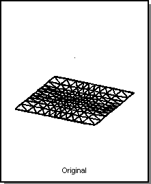
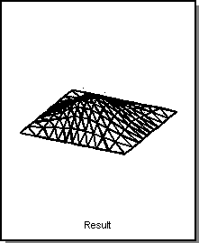
Figure. Point Constraint
Position and Tangent Point Constraints
The deformable modeling solver that finds the one shape w(u) that minimizes the energy of the system is subject to a set of linear constraints. Any geometric constraint that can be expressed as a set of linear math equations can be enforced on the deformable shape while it is being sculpted. The challenge is to find a set of linear equations to describe interesting geometric properties that are to be constrained.
For example, the constraint feature allows ADM to support point position and point tangent constraints on deformable curves. This means that the curve can be made to deform to exactly interpolate a point position or a point tangent while also deforming to minimize its internal energy. At any one time, there can be any number of point constraints located at any set of points on the curve. This combination of effects allows ADM to enforce a complicated set of constraints simultaneously while still deforming a curve to remain fair.
For deformable surfaces, the constraints include point position constraints, point normal constraints, and curve constraints. The shape of a surface can be constrained along the length of any shaped curve within the surface. Also the surface tangent along the length of the constraint curve can be constrained. The curve position and tangent constraints can be used to force one deformable surface patch to attach to another deformable surface patch with either C0 or C1 continuity.
Surface Deformations at Curve Constraint Corners
Wherever a pair of curve constraints intersect one another to form a corner, the surface normal is fixed. For example, consider a simple planar square sheet constrained along its borders and loaded with a distributed pressure. As the gain of the pressure is increased, the planar face begins to bulge and eventually can be made to inflate like a balloon. The surface deformation is smooth everywhere, except at the corners where two curve constraints meet. At these corners, the surface bends sharply to preserve the original surface normal.
The reason for this has to do with differential geometry and not deformable surfaces. For the points in a curve constraint, the curve constraint is equivalent to both a position constraint and a single tangent constraint in the direction of the curve. For most of the points in a curve constraint, the surface may pivot about the curve constraint much like the pages of a book can pivot about the books binding. However, those points which lie on the intersection of two curve constraints effectively have two tangent constraints. And any point in any smooth surface with two fixed tangents has a fixed surface normal.
The corner behavior can be avoided by avoiding corners. Use fillets and blends to remove corners in constraint curves before sculpting. Without the corners, the surface is able to deform at every point within the surface.
Curve Constraints
Curve constraints and curve loads share the same underlying implementation; curve loads are the recommended method.
Link Constraints
The deformations of the surfaces within a deformable modeling mesh are coupled at run time by the addition of a set of link constraints. A link constraint is a form of the general curve constraint.
Interestingly, the two surfaces can be made to be tangent continuous across a link constraint without being position continuous by omitting the constraint on position while using the cross tangent constraint. The behavior of the system under these circumstances is inappropriate for modeling manifold objects, but does make an interesting modeling effect for systems which need to crack and split, like modeling sub-surface structures that show separations due to faults.
The multi-surface deformable modeling package allows the end user to specify the behavior of the link constraint at run time. The behavior of the link constraint describes how the position and the cross-tangent properties of the two curves within the link constraint are related to one another. For position or cross-tangent properties, each curve may have one of three behaviors: linked, fixed, or open.
A linked behavior means that a property of the curve on one side of the link constraint is equal to the same property of the curve on the other side of the link constraint. The link constraint equations shown in the last section describe the linked behavior of a link constraint. A fixed behavior means that the position or the cross-tangent property of a curve in a link constraint is constrained. Rather than being free to move so that it can be connected to the other curve, the shape of the curve is fixed and is not modified by subsequent deformations. An open behavior means that a property of one of the curves in the link constraint is not constrained at all. It is free to change as the mesh is deformed but it does not necessarily move to stay connected to the other curve in the mesh.
The overall behavior of the link constraint is determined by the behaviors assigned to each property on each curve. The following table shows the links behavior given the various possible behavior states for each of the links curves. One such table exists for each property that the link constraint controls. The behavior state for each curve in the link constraint can be modified at run time.
Table. Link Behavior for Combined Link Curve Behaviors
|
Behavior_curve_2 |
|||
|
Behavior_curve_1 |
Open |
Fixed |
Linked |
|---|---|---|---|
|
Open |
Off-off | Off-fixed | Linked-linked |
|
Fixed |
Fixed-off | Fixed-fixed | Fixed-fixed |
|
Linked |
Linked-linked | Fixed-fixed | Linked-linked |
Default Shapes
The default shape is that which the automatic minimization procedure seeks in the absence of any constraints and loads. There are two options for setting the default shape:
- The current shape may be captured as the default shape.
- The default shape may be set to zero.
A zero default shape is useful for constructing elegant surfaces stretched between curve constraints, much like soap films stretched across coat hangers. A nonzero default shape is useful for designing a small, smooth deviation from the given input shape.
A deformable model will always have a default shape set immediately after startup. If the model is restored from attributes with a stored default shape set, then that will be used; otherwise Set_default_shape(1) will be called automatically. The intent of this behavior is that calling Solve_dmod immediately after reading in a model is a null operation. If this behavior is not desired, then Set_default_shape(0) can be explicitly called to erase the default shape.
The default shape feature may be used to deform shapes very far from their original shape by breaking one large deformation into a set of smaller deformations interspersed with default shape captures. In such a situation, the deformed shape is a function of its default shape and the current set of applied loads. Alternatively, when attempting to create a smooth surface connecting a framework of curve constraints, the default shape can be removed or zeroed. Thus, the shape of the deformed surface becomes only a function of the curve constraints and the current set of applied loads.
Tight State
Tight state is a property of curve (single-surface) or link (multi-surface) loads and constraints that interacts with the default shape. When the default shape is set for a deformable model, all of the constraints and loads for that model should be "satisfied" with the default shape. This is true even when there is a gap between the shape of the (curve or link) load on the default surface and the target shape of the load.
When tight_state is set to 0, the load attempts to pull the model onto the default shape, rather than the target shape. The load is satisfied when the surface shape is the default shape. When tight_state is set to 1, then the load requires to be tight, and thus, pulls onto its target shape. This could indicate that the load is dissatisfied with the default shape, and attempts to change it when a solve() is performed.
When the default shape of a deformable model is set by calling ATTRIB_DM2ACIS::Set_default_state(1), the tight state of all the curve and link loads and constraints is set to 0 (not tight, that is, satisfied with the default shape). Changing the behavior of a load or constraint also sets tight state to 1 (tight), as does explicitly calling ATTRIB_DM2ACIS::Set_tight_state(1).
Parameters
The automatic behavior of a deformable model may be altered by changing the deformable modeling parameters. These are the weights used to model the internal energy of the deformable curve or surface.
The deformable modeling parameters include:
- alpha
- The deformable models resistance to stretch.
- beta
- The deformable models resistance to bending.
- gamma
- The deformable models resistance to the rate of change in bending.
- delta
- The deformable models resistance to deviations from the default shape.
The alpha variable directly weights the amount of energy due to stretching. In a curve, the alpha weighted term is identical to arc length. Stretch is a local measure of the overall length of a curve and alpha weights the resistance to it. A curve with a large alpha value is said to be stiff. Deformable models with large alpha values act like soap bubbles seeking to always minimize their area. This results in flatter looking surfaces that allow regions of rapid bending.
Deformable models with large beta values act like elastic beams attempting to distribute regions of bending over large areas and generate very fair shapes. It would be convenient if the beta weighted term were identical with curvature. However, the parametric representation of curvature is a rational nonlinear function of wu and wuu. Minimizing this actual quantity would be computationally prohibitive. Fortunately, the beta variable does weight the term that dominates the actual curvature for small deflections and thereby weights the energy due to bending. Larger and larger curvatures continue to increase the energy although the linear approximation to curvature no longer is valid. Additionally, the bending energy weighted by beta can only be zero when the curve is flat. So although beta does not actually weight a curvature measure, it does act to resist curve bending.
The gamma term is another smoothing term that works well for deformable curves. Resisting the rate of change of bending helps to resist the rate of twist in a curve, which helps to increase the fairness of a deformable curve. The gamma does not work well with deformable surfaces.
Delta is the gain of a distributed spring force that connects the deformed shape to the default shape. Deformable models with nonzero delta values resist the affects of spring loads and point constraints. Delta is provided as another tool for affecting the behavior of the deformable model while being sculpted. It is not necessary for enforcing the default shape behavior of the deformable model. Even with a zero value for delta, the deformable model continues to seek out the default shape when no loads or constraints are applied.
The actual deformable models sculpting behavior is a function of the ratios of these parameters. A good starting set of surface parameters are alpha = 1, beta = 5, gamma = 0, and delta = 0.
Tag Objects
Each deformable patch and every load and constraint within a deformable modeling patch is called a tag object. Tag objects are all uniquely identified by a tag number, which is simply an integer managed so each tag associated with a tag object is unique. Functions that create loads, constraints, and patches always return the tag number of the newly created tag object. Functions which modify or delete tag objects always require the tag number as an input argument. The function DM_get_tag_summary returns a list of the current tag numbers and tag types related to a particular deformable patch within a deformable modeling patch hierarchy.
ADM automatically makes an icon for each tag object if icons are turned on. The icons decide how to draw the tag objects (i.e. should you draw three or four lines to make an arrow), and use an abstract base class with a please draw a line interface to the rendering system. The ACIS Deformable Modeling HOOPS (ADMHOOPS) component contains concrete instantiations that implement please draw a line in terms of HOOPS calls. This means that ADM uses ADMHOOPS only when the customer chooses to use rendering.
Parametric Positions
A location on a curve or surface is identified by a parametric position specified by uv coordinates (surfaces) or u coordinates (curves). All deformable model curves and surfaces are parameterized on the unit square. That is, the parameter values always vary from 0 to 1 with the value of 0.5 being the middle. Any scaling required to map the deformable model parameterization to that of the internal deformable model parameterization is made by the deformable modeling package for the user.
Interfaces
ACIS provides several interfaces to access deformable modeling.
User Interface
The ADM implementation is a C++ library. It comes with three user interfaces: a C++ programmable interface, a Scheme interpreter interface, and an example mouse interface for interactive sculpting.
The programming interface consists of API functions and a family of sculpting methods supported by the ATTRIB_DM2ACIS C++ object. The API functions include:
- Initialize function that extracts data from ACIS models to build ADM models
- Commit function which places sculpting results back into the source ACIS model
- End sculpting function that deletes the ADM model after it is no longer needed
- Add patch function that creates child patches on their parent patches
- Copy patch function that creates new child patches as copies of existing patches
- Remove patch function that removes and deletes child patches from their parents
- Function that sets the tolerance level used when enforcing curve constraints
The tolerance function is always called by the initialize function to force the ADM system to make its calculations to the same tolerance level used by the ACIS package. This will probably never be called directly by an application programmer.
The second ADM interface consists of a set of Scheme extensions that expose the API functions and ADM methods to the Scheme interpreter.
The third ADM interface consists of a set of Scheme files which build an ADM rubberband capability. This allows users to experiment with mouse-based sculpting and a language of one- and two-letter sculpting commands to simplify exercising the ADM Scheme extensions. Additionally, a small set of canned demonstrations are provided which run simple sequences of the sculpting commands for deformable curves and surfaces.
API Interface to Multi-Surface Deformable Modeling
The basic strategy for building a multi-surface mesh in the ADM API is to make a deformable model for every surface in the mesh, and then to add a link constraint for every connection within the mesh. In pseudo code this sequence looks like the following.
//for every surface in the mesh
For(ii=0;ii<surface_count;ii++)     {
       // define the surfaces shape function
       pfunc_array[ii] = DM_make_bspline_surface(
           rtn_err, ...);
       // make the surfaces deformable model
       surface_dmod[ii] = DM_make_dmod_surface(
           rtn_err, pfunc_array[ii],
...);     } // end iterate every surface in the mesh
// for every edge in the mesh
for(ii=0;ii<edge_count;ii++)     {
       // find the faces for the edges
       face1_index = USER_get_face_index_for_edge(edge[ii],1) ;
       face2_index = USER_get_face_index_for_edge(edge[ii],2) ;
       // build the domain curve description
       src1_C_pfunc = USER_make_pfunc_for_edge_on_face(
           edge[ii],face1_index) ;
       src2_C_pfunc = USER_make_pfunc_for_edge_on_face(
           edge[ii],face2_index) ;
       // build the link cstrn
       link_tag[ii] = DM_add_link_cstrn(rtn_err, tag_shift,
           surface_dmod[face1_index],surface_dmod[face2_index],
           domain_flag, src1_C_pfunc, src2_C_pfunc,...) ;     }
// end iterate every edge
|
After the multi-surface mesh is constructed, a call to DM_solve computes the deformed shape for the entire multi-surface mesh.
The new extension to the API is the function DM_add_link_cstrn. As a side effect this function connects individual deformable models into a multi-surface mesh. There is no API command for assembling surfaces into a mesh. The DM_rm_tag_object command has been extended to act properly when removing link constraints or surfaces from a multi-surface mesh. Use the DM_get_sibling function to walk the list of surfaces in the multi-surface mesh. Use the DM_parse_tag_flag function to find the first root-sibling in the deformable model hierarchy given a pointer to any member deformable modeling object.
The link constraint consists of two curves each having two properties that may be constrained in three different manners. Each link constraint, due to symmetries in the behavior table, can exhibit 25 different behaviors. The behavior state is communicated to the deformable modeling library as a bit array. The array is called the links behavior and it is composed of an OR of the following bits.
Table. Behavior Bits for API Interface
| Behavior | Position | Tangent |
|---|---|---|
| Curve 1 | DM_POS_FREE | DM_TAN_FREE |
|
|
DM_POS_FIXED | DM_TAN_FIXED |
|
|
DM_POS_LINKED | DM_TAN_LINKED |
| Curve 2 | DM_POS_2_FREE | DM_TAN_2_FREE |
|
|
DM_POS_2_FIXED | DM_TAN_2_FIXED |
|
|
DM_POS_2_LINKED | DM_TAN_2_LINKED |
The behavior state for each curve in the link constraint can be set at the time the link constraint is created through the function DM_add_link_cstrn and can be queried and modified subsequently with the functions DM_get_cstrn_behavior and DM_set_cstrn_behavior.
Area Constraint User Interface
In ADM, API area constraints are added with the function DM_add_area_cstrn which requires a DS_zone object as input. A rectangular DS_zone object can be constructed with the routine DM_build_square_zone. Only domain space rectangles are permitted as zone shapes. Area constraints are tag objects and can be constructed, queried, modified, and removed from the model using the functions listed below.
Constructed by:
| DM_build_square_zone | DM_add_area_cstrn |
Queried and modified with:
Removed with:
| DM_rm_tag_object |
DS_zone Objects Overview
API area constraints are added by the function DM_add_area_cstrn which requires a DS_zone object as input. A rectangular DS_zone object can be constructed with the routine DM_build_square_zone. Area constraints are tag objects which can be constructed, queried, modified, or removed from the model.
A DS_zone object partitions a deformable models shape into two regions, inside or outside the zone. Because the zones boundaries may not align with the deformable models elements boundaries, a zone partitions the elements of the affected shape to also include those elements crossing the zones boundary.
To construct a DS_zone object, define the boundary shape within the domain space of the deformable modeling shape. To construct a rectangle zone, define the minimum and maximum corner locations of the rectangle.
A constructed zone can return:
- A list of all elements which are completely in the zone
- A list of all the degrees of freedom that affect the shape of the in-elements
- The local list of degrees of freedom that affect the shape of the in-elements only
A degree of freedom in the local list affects the shape of the zones in-elements only. A degree of freedom in the total list may also affect the shape of elements not completely within the zone.
A DS_zone object partitions a deformable models shape into two regions, inside or outside the zone. Because the zones boundaries may not align with the deformable models elements boundaries, a zone partitions the elements of the affected shape to also include those elements crossing the zones boundary.
To construct a DS_zone object, define the boundary shape within the domain space of the deformable modeling shape. To construct a rectangle zone, define the minimum and maximum corner locations of the rectangle.
Optional Drawing Libraries
The optional example drawing libraries provide low-overhead drawing functionality with a flexible, incremental development path. Application developers can modify or replace some or all of the optional drawing libraries by overriding the interface classes.
The ADMHOOPS component is provided as sample code, showing customers how to hook rendering code into the ACIS Deformable Modeling Component. If an ACIS customer uses both ADM and HOOPS components, the ADMHOOPS component is required to hook ADM into HOOPS. Customers not using HOOPS should emulate the overrides of the ADM_regobj classes found in ADMHOOPS, if they want to take advantage of deformable modeling drawing support
Clients of the optional drawing libraries must call the corresponding initialize and terminate routines on startup and end. Replacing an optional library will require writing an initialize and terminate routine. The main responsibility of the initialize routine is setting up the appropriate factory.
Implementations of the interface classes DM_icon and ADM_regobj must provide a virtual constructor, in the form of a factory. The factory must provide a method for deleting the objects it constructs. For the DM_draw_engine, the factory responsibilities are taken on by the DM_draw_engine implementation. Example factory objects are the DM_default_icon_factory in the dmicon library and the ADM_hoopsregobj_factory in the admhoops library.
For each of these interface classes, ADM has a singleton manager object, which holds a pointer to the factory. The library initialize routine sets this pointer. Leaving the pointer null deactivates ADM rendering support. The manager objects are the DM_icon_factory_mgr and DM_draw_engine_mgr in the ACIS Deformable Modeling Component, and the ADM_regobj_factory_mgr in the Standalone Deformable Modeling Component.
dmicon
The dmicon library provides icon objects for all deformable modeling tag objects (surfaces, curves, constraints, and loads). A common command/query interface is provided by the DM_default_icon base class, which derives from the DM_icon interface class. The library also provides an example icon factory, which is used to automatically create icons for tag objects.
Mouse Action in Scheme
The following table summarizes mouse and keyboard controls for interactive modeling using Scheme.
|
Mouse buttons --> Keyboard |
Left button | Right button |
Left & right buttons |
|---|---|---|---|
| None | Rotate view | Zoom view | Pan view |
| Shift | Track point constraint in Z Adjust tangent vector length |
Add a point constraint Toggle a control point on and off |
|
| Shift + drag |
|
Add a patch |
|
| Control | Track point constraint in X & Y Adjust tangent vector direction |
Add a pressure point |
|
| Shift + Control | Adjust slide gain Adjust dual tangent vectors independently |
Remove a tag |
|
Limitations
There are a few limitations in this version of ADM, as outlined below.
- Link constraint issues
- No child multi-surface patches
- No multi-edge mesh
- No tracking curve constraints
- Trim face rendering considerations
- Exception handling across interfaces
- Sculpting non-pseudoplanar surfaces
- Surfaces with non-uniform parameterizations
In this release, material properties, loads, and constraints (other than link constraints) continue to be applied to individual deformable models. For example, if an application desires to apply a pressure over an entire multi-surface mesh, the application is obligated to apply a distributed pressure to each surface within the mesh.
Link Constraint Issues
The default for ADM is to use curve loads. If you choose to turn this off, you may experience the following problems.
Link Constraints Across Surface Boundaries
To deform nicely, the link constraints in a deformable modeling mesh must all be located at the boundaries of the surfaces being linked. Currently, link constraints acting across trimmed curve boundaries within the surfaces being linked will not deform nicely; they will tend to be very rigid.
Link constraints in a deformable modeling mesh must all be located at the boundaries of the surfaces being linked.
Stiffened Link Constraints
Link constraints can be added between surfaces whose underlying parameterizations differ. The surfaces as shown in Figure. A Multi-surface Deformation Mesh have a shared underlying parameterization because all the knot values as shown by the locations of the drawn isoparameter lines match up with one another. However, as shown in the following figure, surfaces can have varying isoparameter lines.
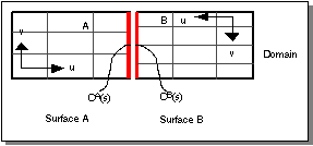
Figure. Mismatched Parameterized Multi-surface Mesh
Whenever a link constraint connects two surfaces with different parameterizations the behavior of the link constraint is slightly stiffer than expected. This behavior is due to the nature of Bspline and NURB representations and the fact that the link constraints acts to make the two curves be exactly the same shape without tolerances (other than numerical round off).
The general rule describing this behavior is that a link constraint acts as a single polynomial curve (or rational polynomial curve for NURBS) of the lowest degree seen in the two surfaces being connected over the region between matching sets of knot values. This means that if the example in the previous figure were augmented to place an addition knot in surface A that was aligned with one of the internal knot values of surface B, the link constraint would act as a 2piece piecewise continuous cubic curve.
No Child Multi-Surface Patch
Only root deformable models are allowed to form deformable modeling meshes. Child patches continue to be limited to being single deformable modeling patches. In addition, a child patch continues to be totally contained by its single parent. This limitation prevents child patches from spanning across link constraints.
No Multi-Edge Mesh
Multi-surface meshes are supported, but multi-edge meshes are not. (See also Deforming Surfaces.)
No Tracking Curve Constraints
Currently, the shape of the link constraints can not be specified by the application and all the surfaces can not deform to follow a changed curve shape. Tracking curve constraints are isoparametric only. There are no limits on curve load tracking.
Trim Face Rendering Considerations
The ADM Scheme graphics are based on the underlying ACIS faces, rather than the untrimmed surfaces. This gives true trimmed rendering of the portion of the deformable surface that contributes to the ACIS model. Users should be aware, however, that this is only a rendering effect. The following issues should be considered.
Deformable Model Energy
Surface regions outside trim boundaries still contribute to the surface energy; ADM will still try to minimize bending and stretching of the surface beyond the trim boundaries.
Surface Auxiliary Graphics
Surface control point and surface element displays still extend beyond trim boundaries. This may be useful for displaying the extent of the underlying surface.
Tag Objects Outside Face Boundaries
It is the users responsibility to ensure that loads and constraints are placed correctly. While trimmed portions of surfaces are no longer displayed, it is still possible to place loads or constraints outside the trimmed boundaries.
Exception Handling Across Interfaces
Exception handling across interfaces is problematic, because different libraries may have different exception handling methods, such as C++ try/catch or C setjmp/longjmp. The Spatial_abs_hurler interface class provides a protocol for handling exceptions across interfaces. Interface routines taking a Spatial_abs_hurler agree to trap all exceptions, translate them to an integer code, and then call the Spatial_abs_hurler::rethrow_error method with the integer code.
Sculpting Non-pseudoplanar Surfaces
Deformable Modeling is a method for translating local inputs into smooth, global changes in the shape of a surface. It can be thought of in terms of pushing and pulling on a 2D rubber sheet (as opposed to a 3D rubber solid). Because of the 2D nature of the smoothing term in Deformable Modeling, it is best suited to working with "pseudoplanar" surface regions, that is regions of a surface for which the normal vectors all point roughly within 20-40 degrees of the same direction. The issue is that non-pseudoplanar surfaces (such as a torus or cylinder) can be associated with an enclosed volume; this is especially true if the surface is closed. Since the deformation energy models 2D sheets rather than 3D volumes, the enclosed volume does not behave in a physically intuitive manner when the corresponding surface is deformed. For example, imagine pulling radially outward at two opposing points on a cylindrical pant leg in an attempt to stretch the shape; the points which are being pulled move outward, but the "sides" of the cylinder away from the pulled points actually move inward, causing an unexpected shape. However, if the cylinder is clamped down roughly 30 degrees to either side of the pulled points, the deformation is limited to two pseudoplanar regions of the cylinder and the resulting shape is as expected.
For this reason, it is best not to use Deformable Modeling to form complex shapes from first principles. Instead, standard modeling techniques should be used to obtain a rough shape, which can then be adjusted using Deformable Modeling.
Surfaces with Non-uniform Parameterizations
The energy function which is minimized in Deformable Modeling depends on parametric (rather than geometric) derivatives of the surface. This causes surfaces with highly varying parametric velocities (i.e. where the coordinate lines are much closer together in one region of the surface than another) to be stiffer in regions where the parametric velocity is low than in regions where it is high. For example, a cone will be stiffer near the apex, where the radial coordinate lines are close together, than at the base. This effect should only be significant for surfaces with a large variation in parametric velocities, usually due to a coordinate singularity as on a sphere or a cone.
[Top]
© 1989-2007 Spatial Corp., a Dassault Systèmes company. All rights reserved.