Sweeping with Options
The sweep_options class is used for each overloaded api_sweep_with_options call. To use anything other than the default options, an instance of this class should be created. The data structure within this class establishes default values for the options that are not set by the caller. The options are set using a set_<option name> methods present for each of the options in the class. The same names are used for the API and the Scheme extension sweep:options. In Scheme, the option names are passed into the Scheme extension within quotation marks. The following sweep options are grouped based on the functionality controlled by the options.
Table. Sweeping Options Summary
|
Sweeping Options |
||
|---|---|---|
|
Categories |
Options |
Remarks |
|
Sweep To: |
sweep_to_body |
Sweeping to a body allows the specification of the end of the sweep via the location where the sweep intersects the body specified. When these options are used, the result of the sweep is returned in the new_body argument to api_sweep_with_options. |
|
Sweep to body results |
bool_types, keep_branches, keep_law |
This set of options controls what portions of the sweep result and body being swept to remain after the sweep operation is completed. |
|
Object to sweep to |
to_face |
Used for backward compatibility. Instead of specifying a body to be used for clipping the end of the sweep, a surface underneath a face is used. The disadvantage of using this option is the surface of the face must be defined over the entire area that the sweep intersects. |
|
Sweeping with Draft |
|
Allows the profile to be expanded and contracted as it is swept along the path. Drafting works best when sweeping along linear paths. For non-linear paths, the amount of draft is calculated based on taking the parametric length along a straight path and applying this offset at the equivalent parameters along the non-linear path. This may cause the result to appear different than expected. |
|
Draft amount |
draft_angle, end_draft_dist, draft_law |
The amount by which the profile is offset along the path is specified by these mutually exclusive options. |
|
Draft Results |
draft_hole, draft_repair, gap_type |
Additional options for further specification of draft capability. |
|
Sweeping about an axis |
sweep_angle, steps, close_to_axis |
These options are used in conjunction with the api_sweep_with_options accepting the path in the form of a position and vector which define an axis. |
|
Profile Orientation and Twisting |
rail_law, rigid |
Controls how the profile is oriented while it is swept along the path. |
|
Sweeping with twist |
twist_angle, twist_law |
Allows the profile to be rotated perpendicular to the path as it moves along the path. |
|
Path Used |
portion |
Allows for greater granularity to be defined when specifying an entity as the path. |
There are six basic areas of consideration for sweeping (as outlined in the Sweeping Options table).
-
Sweep To: options define how the sweep ends. This includes how and when specific pieces considered for keeping or eliminating are handled and whether the sweep ends at an object (versus sweeping a distance, for example).
-
The Draft options define the construction and results of a draft sweep. This also includes how specific pieces are handled.
-
Axis Sweeping options also define basic sweep functions except to be attached to an axis.
-
Profile Orientation and Twisting allows the Sweep functionality to include twisted profiles and rail laws.
-
The Path Used capability allows the sweep to be applied with a finer granularity when specifying an entity path.
-
The Sweep Results options help further define results such as the ending of the sweep, mitering, and what to do with the leftovers.
Sweep To:
Sweeping to a body allows the specification of the end of the sweep via the location where the sweep intersects the body specified. When these options are used, the result of the sweep is returned in the new_body argument to api_sweep_with_options.
Sweeping to a Body
The option sweep_to_body specifies a pointer to the body where the sweep is to complete. sweep_to_body allows multiple faces on a body to be used for properly clipping the result(s). The to_face option only allows a single surface to be used to clip the sweep result. Equivalent results could be obtained if a profile were swept through a body, and then the two bodies were Boolean united together. The default is NULL.
The sweep_to_body must be a sheet body (that is, an open body) if the sweep profile must result in a sheet body. The profile is an open wire-body or edge, or a closed wire-body with the solid option set to TRUE.
The sweep_to_body option is mutually exclusive with to_face.
The following figure shows a circular profile swept to a bracket.
Scheme Example
| ; Sweep to a body (define bracket1 (solid:block (position 0 0 0) (position 10 10 10))) (define b2 (solid:block (position 0 0 5) (position 7 10 10))) (define b3 (solid:block (position 3 0 2) (position 7 10 10))) (solid:subtract bracket1 b2) (solid:subtract bracket1 b3) (define profile (edge:ellipse (position -5 5 5) (gvector 1 0 0) 2)) ; OUTPUT Original (define opts1 (sweep:options "sweep_to_body" bracket1 "bool_type" "subtract" "keep_law" "true" "keep_branches" #t)) (define sweep1 (sweep:law profile (gvector 20 0 0) opts1)) ; Run the rebuild command to update the visual graphics. (render:rebuild) ;; () ; OUTPUT Result |
Example. Sweeping to a Body

Figure. Sweep to a Body
Using Selective Booleans
The option bool_type works with sweep_to_body to specify what should be done with the pieces of the profile that were removed during the sweep. This specifies how the selective Booleans are used within sweeping.
- LIMIT
- creates a body which is the result of the sweep up to the location of the intersection between the sweep and the fixed body. This the default setting.
- UNITE
- creates one body out of the fixed body and the result of the sweep up to the location of the intersection between the sweep and the fixed body.
- INTERSECT
- creates one or more pieces resulting from the intersection of the fixed body with the swept body.
- SUBTRACT
- modifies the fixed body by removing material equivalent to the swept body.
- KEEP_BOTH
- creates a body equivalent to the limit type without deleting the original body.
bool_type returns the created body, which is the result of the sweep up to the location of the intersection between the sweep and the fixed body, without deleting the fixed body. bool_type also controls the numbering on the cells of the tool body and the blank body. The number of cells can affect the results of a defined keep_law.
The following figure illustrates the results of defining the bool_type as limit. What was thrown away in the Figure. Sweep to a Body, is precisely what is kept here.
Figure. Sweeping with Boolean Types
Branches
The keep_branches and keep_law options work with the graph created when sweeping to a body. The keep_branches option specifies whether or not graph branches should be kept. TRUE means all branches are kept. The sweep_to_body option must be specified when using keep_branches.
The following figure shows a circular profile swept to a bracket. The sweep options used are bool_type, to_body, keep_law, and keep_branches. The to_body sweep option specifies that sweeping will to stop at the bracket body. The bool_type sweep option is set to SUBTRACT which means that any overlapping portion of the circular profiles volume is removed from the bracket. The rendered illustration on the right shows what is desired. This example introduces some ambiguities where the swept profile only partially intersects the bracket body.
Figure. Keeping Sweep Branches
The following figure shows how the graph theory decomposes the tool (cylinder) body into graph vertices and graph edges. Most of the tool body is linear. The option keep_branches defines whether the branches are important, and should be kept or should be ignored and thrown away. In this case, the branch is the half circle resulting from the tool cylinder body intersecting the bracket body. (For more information, refer to the section Graph Theory.)
Figure. Keeping Branches Graph Theory
The following figure shows graph representing a blank body and a tool body. The tool body can be thought of as a circular profile that is swept through the blank body. If a keep_law is to be used to specify which cells are to remain after the sweep operation, the law needs to be aware of where the cell numbering begins.
Figure. Bool_Type Affects Cell Numbering
Using the Keep Law
The option keep_law allows more specific definition of the portions of a graph to be kept than the sweep option sweep_to_body. Laws, primarily conditional tests, can be used to specify what is used for the sweep operation. When keep_law is TRUE, all graph pieces are saved. (For more information, refer to the section Graph Theory.
When keep_law is not TRUE, the graph elements are first ordered and numbered. bool_type directly impacts the cell numbering of the tool body and the blank body. The starting cell number and the cells that are included in the number are different depending on the bool_type operation. Knowing the number associated with the specified bool_type then provides insight into a conditional law defined for the keep_law, like "x>2 AND x<5". The letter x should be used for the pieces to keep. The letter y is always the last numbered piece. The sweep_to_body option must be specified when using keep_law.
Scheme Example
| ; Sweeping with boolean types (define bracket1 (solid:block (position 0 0 0) (position 10 10 10))) (define b2 (solid:block (position 0 0 5) (position 7 10 10))) (define b3 (solid:block (position 3 0 2) (position 7 10 10))) (define subtract1 (solid:subtract bracket1 b2)) (define subtract2 (solid:subtract bracket1 b3)) (define profile (edge:ellipse (position -5 5 5) (gvector 1 0 0) 2)) ; Run the rebuild command to update the visual graphics. (render:rebuild) ;; () (roll:name-state "original") ; OUTPUT Original (define opts1 (sweep:options "sweep_to_body" bracket1 "bool_type" "subtract" "keep_law" "true" "keep_branches" #t)) (define sweep1 (sweep:law profile (gvector 20 0 0) opts1)) ; Run the rebuild command to update the visual graphics. (render:rebuild) ;; () ; OUTPUT Subtract (roll "original") (render:rebuild) (define opts2 (sweep:options "sweep_to_body" bracket1 "bool_type" "unite" "keep_law" 1 "keep_branches" #t)) (define sweep2 (sweep:law profile (gvector 20 0 0) opts2)) ; Run the rebuild command to update the visual graphics. (render:rebuild) ;; () ; OUTPUT Unite (roll "original") (render:rebuild) (define opts3 (sweep:options "sweep_to_body" bracket1 "bool_type" "intersect" "keep_law" 1 "keep_branches" #t)) (define sweep3 (sweep:law profile (gvector 20 0 0) opts3)) ; Run the rebuild command to update the visual graphics. (render:rebuild) ;; () ; OUTPUT Intersect (roll "original") (render:rebuild) (define opts4 (sweep:options "sweep_to_body" bracket1 "bool_type" "limit" "keep_law" 1 "keep_branches" #t)) (define sweep4 (sweep:law profile (gvector 20 0 0) opts4)) ; Run the rebuild command to update the visual graphics. (render:rebuild) ;; () ; OUTPUT Limit |
Example. Using the Keep Law

Figure. Sweep Using keep law
Surface Clipping
The to_face option permits clipping of the swept body at a surface. When working in Scheme, the sweep:options extension expects a pointer to a FACE entity. When using the api_sweep_with_options function with the sweep_options class, a pointer to a surface instead of a pointer to a face entity is required in the sweep_options data structure. The default is NULL. The to_face option is mutually exclusive with sweep_to_body.
Sweeping with Draft
A practical use of drafting is for molded items. As the profile is swept, the ending profile is offset by an equal distance, which facilitates removal of the item from a mold. Extreme draft angles or draft laws can result in errors from self intersecting bodies, incomplete lateral faces (likely at corners), and/or unsupported topologies. The following figure represents an example offset occurring during a draft.
Figure. Drafting
Draft Sweeps with Angle Specifications
The option draft_angle is a real number that represents the angle with which the swept profile is to draft while sweeping. For closed profiles, a positive draft angle causes a draft out, while a negative draft angle causes a draft in. For example, if the profile is a circle in the xy plane, the path is a line along the z-axis, and the draft angle is 30 degrees, the result is an "upside-down" frustum. (A frustum is a cone with its tip cut off. It is upside-down in this case, because the draft angle out resulted in a top base larger than the bottom base.)
The draft angle is measured against the normal of the surface. Therefore, the offset distance is measured in a perpendicular way. In the following figure, Po denotes the position on the surface without draft and P is the position on the drafted surface.
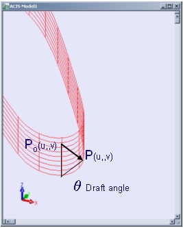
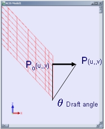
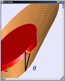
Figure. Draft Distance Measurement
Negative draft angles can result in self-intersecting bodies, which are not permitted. However, the second graphic of the following figure illustrates a negative draft angle that does not result in a self-intersecting body. For open profiles, the positive draft angle is in the direction of the cross product of the tangent of the profile and the tangent to the path.
When a profile is provided, the start point of that profile is important. The sweeping operation moves the profile to this position and starts the sweep from there. In cases with draft angles or laws, the profile is placed at the location where the first degeneration (e.g., change of topology) occurs.
The following example illustrates how to use the Scheme extension sweep:law combined with sweep:options ("sweep_angle") to sweep a face with positive and non self-intersecting negative draft angles.
Scheme Example
| ; draft_angle (define path (edge:linear (position 0 0 0) (position 0 0 10))) (define profile (edge:circular (position 0 0 0) 5)) (define opts (sweep:options "draft_angle" 30)) (define sweep (sweep:law profile path opts)) ; redefine the options to create a negative draft angle. ; OUTPUT Positive Draft (roll) (define opts (sweep:options "draft_angle" -20)) (define sweep (sweep:law profile path opts)) ; OUTPUT Negative Draft |
Example. Sweeping with a Draft Angle
Figure. Sweeping with a Draft Angle
Scheme Example
| ; draft_angle (define path (edge:linear (position 0 0 0) (position 0 0 20))) (define profile (edge:linear (position 0 0 0) (position 0 30 0))) (define opts (sweep:options "draft_angle" 15)) (define sweep (sweep:law profile path opts)) (define color (entity:set-color sweep 3)) ; OUTPUT Original |
Example. Linear Sweep with a Positive Draft Angle
Figure. Linear Sweep with a Positive Draft Angle
The next example illustrates how to use the Scheme extension sweep:law combined with sweep:options ("sweep_angle") to sweep a face with a positive draft angle.
Scheme Example
| ; sweep:law ; Sweep a positive draft angle. ; Create a solid block and get the faces. (define block1 (solid:block (position -10 -10 -10) (position 30 30 30))) ;; block1 (define faces (entity:faces block1)) ;; faces ; Select face to sweep. (define face2 (car faces)) ;; face2 ; OUTPUT Original ; Create a new solid by sweeping the face along ; a gvector. (define sweep2 (sweep:law face2 (gvector 0 0 10) (sweep:options "draft_angle" 15))) ;; sweep2 ; OUTPUT Result |
Example. Sweeping a Face with Positive Draft Angle
Figure. sweep:law - Sweeping a Face with Positive Draft Angle
The following figures illustrate the right hand rule for positive draft convention in open wires.
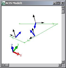
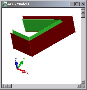
Figure. Positive Draft Convention
In the above figure, positive draft angle (in blue) is defined by the cross product of the profile coedge and the path directions. The result (figure on the right) compared to a sweep operation without draft.
Closed wires and Positive Draft angle definition
If the sweep option solid is enabled (TRUE by default), the positive angle rule is the same as that of faces, where positive means outwards for the expanding solid. If the solid option is set to FALSE, then the result will be a sheet body. In this case, the positive angle rule will be the right hand rule, the cross product between the wire direction (i.e. the coedge direction) and the path direction.
In the following figure, the blue arrow indicates positive draft angle when the solid option is FALSE. The orange arrow indicates positive draft, when the solid option is TRUE. The results can be appreciated better in the following images. The direction of the draft depended on the desired result: sheet bodies use the right hand rule while solid bodies will expand as they are swept.
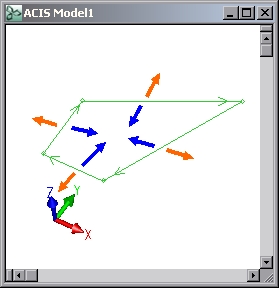
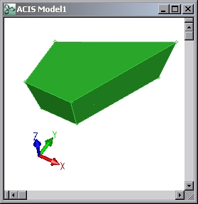
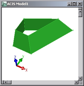
Figure. Left: Closed Wire Body before Sweep with Draft.
Middle: Draft operation completed with solid
option enabled.
Right: Draft operation completed with solid
option disabled.
End Offset Distance
The option end_draft_dist specifies an offset distance (a real number) for the swept surface in the plane where the sweep ends. It is similar to draft_angle, except that an offset distance is used instead of an angle. The larger the defined offset, the wider the draft distance. The default of 0 creates a swept surface parallel with the path. A negative offset creates a swept surface which is closer to the path at the end than at the beginning.
Scheme Example
| ; end_draft_dist (define path (edge:linear (position 0 0 0) (position 0 0 10))) (define profile (edge:circular (position 0 0 0) 5)) (roll:name-state "original") (define opts (sweep:options "end_draft_dist" 5)) (define sweep (sweep:law profile path opts)) (entity:set-color sweep 3) ; OUTPUT Positive Draft (roll "original") (render:rebuild) (define opts (sweep:options "end_draft_dist" -5)) (define sweep (sweep:law profile path opts)) (entity:set-color sweep 3) (render:rebuild) ; OUTPUT Negative Draft |
Example. Defining Offset Distance
Figure. Sweeping with Positive and Negative Offset Distances
Draft Law
The option draft_law is followed by a law or a quoted law string composed of law functions. For example, if the profile is a circle in the xy plane, the path is a line along the z-axis, and the draft law is simply sin(x), the result is something resembling a vase. The value of the law function must be zero at the start. A further restriction is placed when the profile is not G1 continuous: the draft law always must be non-negative or non-positive. The default is NULL.
The following example, whose results are shown in the following figure, sweeps a circular profile along a linear path. As it sweeps, it uses a draft law to create a vase-like appearance.
Scheme Example
| ; Sweeping a vase (option:set "u_par" 10) (option:set "v_par" 10) (option:set "cone_par" #t) (option:set "sil" #f) (define edge1 (edge:linear (position 0 0 0) (position 0 0 25))) (define path1 (wire-body edge1)) (define profile1 (edge:circular (position 0 0 0) 10)) (define vase1 (sweep:law profile1 path1 (sweep:options "draft_law" "6*sin (x/4)"))) ; OUTPUT Original |
Example. Draft Law
Figure. Sweeping a Vase Using draft_law
Scheme Example
| ; Sweep along a multi-edge path with a draft law of sin (x). (define sweep_s1 (sweep:options "draft_law" "sin(x)")) (define pedge1 (edge:linear (position 0 0 0) (position 40 0 0))) (define pedge2 (edge:circular (position 40 20 0) 20 -90 90)) (define path1 (wire-body (list pedge1 pedge2))) (define profile1 (edge:ellipse (position 0 0 0) (gvector 1 0 0) (gvector 0 5 0))) ; Use a draft law in order to get graphics faster. (option:set "silhouettes" #f) (define sweep3 (sweep:law profile1 path1 sweep_s1)) ;; sweep3 ; OUTPUT Original |
Example. Sweep Multi-edge Path
Figure. Sweep Multi-Edge Path
Draft Profile with Internal Loop Handling
The option draft_hole controls the offset behavior of internal loops (or holes) of a profile face when used to sweep with draft. In general, the direction of an internal loops offset is opposite from the periphery (outer loop). Therefore, the draft direction of a hole is opposite from the periphery loop.
- AGAINST_PERIPHERY
- Holes are swept with the opposite draft direction as the periphery loop. This is the default setting of the draft_hole option.
- ANGLE value
- Holes are swept with the given draft angle. The draft angle can be different from the angle for the periphery loop.
- NO_DRAFT
- Holes are swept without draft.
- WITH_PERIPHERY
- Holes are swept with the same draft direction of the periphery loop.
The syntax in Scheme AIDE is similar to:
| (sweep:options draft_hole against_periphery [... other options]) |
When using the associated Scheme code in the following example, the roll operations undo the previous sweep and permit a new sweep to be performed.
Scheme Example
| ; draft_hole (define a_block (solid:block (position 0 0 -20) (position 10 10 -10))) (define a_cyl (solid:cylinder (position 5 5 -10) (position 5 5 -20) 2)) (define hole (bool:subtract a_block a_cyl)) (define prof_body (face:unhook (list-ref (entity:faces hole) 1))) (sheet:2d prof_body) (define prof (car (entity:faces prof_body))) (define delete (entity:delete hole)) (define path (gvector 0 0 20)) (define sw (sweep:law prof path (sweep:options "draft_angle" -10))) ; OUTPUT Upper Left (roll) (define sw (sweep:law prof path (sweep:options "draft_angle" 10 "draft_hole" "with_periphery"))) ; OUTPUT Upper Right (roll) (define sw (sweep:law prof path (sweep:options "draft_angle" -16 "draft_hole" "no_draft"))) ; OUTPUT Center Left (roll) (define sw (sweep:law prof path (sweep:options "draft_hole" "by_angle" 30))) ; OUTPUT Center Right (roll) (define sw (sweep:law prof path (sweep:options "draft_angle" 16 "draft_hole" "by_angle" 30))) ; OUTPUT Lower Center |
Example. Internal Loop Offset
Figure. Internal Loop Offsets
Draft Degeneracy Repair
In ACIS, surfaces created when sweeping with draft are defined by continuously offsetting the original profile along the path. If the offset amount is too large, an edge of the profile could be completely trimmed by adjacent edges. The draft_repair option handles this problem.
For the robustness and accuracy of sweeping with draft, the profile must be planar and the path must be tangent continuous between joints.
draft_repair controls the level of detection for degeneracy during sweeping with draft. The default setting is DEGENERACY. The levels of control include:
- DEGENERACY
- The sweep operation removes degenerate edges in the profile and creates a new profile to continue sweeping. For example, in the following figure, the sweep operation creates a new profile made of edges e2, e3, and e4 and uses this profile after e1 degenerates. This setting checks only adjacent faces for profile changes.
- FIRST_DEGENERACY
- The sweep operation stops at the first degenerate location, as shown in the following figure.
The syntax in Scheme is similar to:
| (sweep:options draft_repair first_degeneracy [... other options]) |
The following figure illustrates a degenerate case where edge e1 is completely trimmed by e2 and e4. The sweep operation needs to detect the degenerate location and reset the profile to keep sweeping along the path.
Scheme Example
| ; Profile degeneracy (define e1 (edge:linear (position 0 0 -10) (position 8 0 -10))) (define e2 (edge:linear (position 8 0 -10) (position 10 6 -10))) (define e3 (edge:linear (position 10 6 -10) (position 10 10 -10))) (define e4 (edge:linear (position 10 10 -10) (position 0 0 -10))) (define prof (wire-body (list e1 e2 e3 e4))) (define path (wire-body (edge:linear (position 0 0 -10) (position 0 0 8)))) ; OUTPUT Start (define sw (sweep:law prof path (sweep:options "draft_repair" "first_degeneracy" "draft_angle" -10 "solid" #t))) ; OUTPUT Finish |
Example. Using draft_repair
Figure. Sweeping to First Profile Degeneracy Location
Gap Repair
The gap_type option is an integer (enumeration) that specifies how to fill in gaps created by offsetting. The default is NATURAL. Consider the wire body made up of a square and a circle, as shown in the following figure. When this wire body is swept with a draft angle (e.g., offset), a gap is created at certain junctures. Valid values are:
- EXTENDED
- 0: draws two straight tangent lines from the ends of each segment until they intersect.
- ROUNDED
- 1: creates a rounded corner between the two segments.
- NATURAL
- 2: extends the two shapes along their natural curves, e.g., along the circle and along the straight edge, until they intersect.
Figure. Gap Fill Types
Axis Sweeping
These options allow for the sweep to use a position and vector as the path. The angle of the revolution can be defined, and the geometry can be simplified (refer to Steps). A solid can be created from an open wire body.
Revolve on Sweep
The sweep_angle option specifies the angle to sweep around an axis, given in radians. The default is "2.0*M_PI". Note that Scheme accepts this in degrees while C++ uses radians. Refer to the following example for a demonstration.
Scheme Example
| ; Sweep angle ; Create a profile (define profile1 (edge:ellipse (position 0 0 0) (gvector 0 1 0) 5)) ; Define an angle and axis to sweep about (define sweep1 (sweep:law profile1 (position 15 0 0) (gvector 0 0 1) (sweep:options "sweep_angle" 135))) ; OUTPUT Result |
Example. Angled Sweep
Figure. Angled Sweep
Linear Segmented Revolve
The Steps option allows conversion of a circular sweep path into the specified number of linear segments. The results are polygons, and the intent is to create simpler geometry by keeping faces planar. The default is 0.
Because of the advantages of having the profile perpendicular to the path when an angle is less than 360 degrees is used, the beginning and ending segments of the path are half segments.
Revolved Solid Body from Open Wire Body
The close_to_axis option allows a solid body to be created from an open wire body profile. When TRUE, the ends are extended to the axis. Care should be taken so that all of the profile is on one side of the axis, to avoid a self-intersecting body. The default is FALSE.
Profile Orientation and Twisting
The rail_law and rigid options control the orientation of the profile during a sweep along a path. The twist_angle and twist_law options allows the profile to be rotated perpendicular to the path during the sweep.
Rail Laws
A rail law is simply a vector field along the sweep path. The field is made of
unit vectors that are perpendicular to the path. An array of rail laws supplied
to the sweep operation dictates how the profile is to be oriented on the path.
The size of the rail law array is determined by the number of segments in the
path. Each path segment has its own associated rail law. Because of this, the
get function for this option requires a specific rail law to be defined.
The number of rail laws can be found through
get_rail_num().
The rail_laws option specifies the orientation of the profile as it is swept along the path. If not explicitly specified, the sweep functions use default rails. Care should be taken when using something other than the default rail laws. The resulting vector field must be unitized and perpendicular to the path at all times. More information on the default rail orientation and on deviating from the default is provided in this section and in the Kernel Component, under the api_make_rails function.
The following example demonstrates sweeping a simple profile along a nonplanar path. In order to line the profile up with the sweep path, a rail law must be defined.
Scheme Example
| ; sweep:law ; To demonstrate the rail laws ; Create a sweep path from points. (define plist1 (list (position 0 0 0) (position 10 0 0) (position 10 10 0) (position 10 10 10))) (define start1 (gvector 1 0 0)) (define end1 (gvector 0 0 1)) (define path1 (edge:spline plist1 start1 end1)) (define law1 (law "cur (edge1)" path1)) (define rail1 (law "minrot (law1,vec (0,-1,0))" law1)) (define edge1 (edge:linear (position 0 1 1) (position 0 1 -1))) (define edge2 (edge:linear (position 0 1 -1) (position 0 -1 -1))) (define edge3 (edge:linear (position 0 -1 -1) (position 0 -1 1))) (define edge4 (edge:linear (position 0 -1 1) (position 0 1 1))) (define profile1 (wire-body (list edge1 edge2 edge3 edge4))) ; OUTPUT Start (define 1sweep (sweep:law profile1 path1 (sweep:options "rail_law" rail1))) ; OUTPUT Finish |
Example. Using Rail Laws to Orient a Profile
Figure. Using Rail Law to Orient a Profile
Rigid Sweep
A rigid sweep is one in which the profile that is swept is translated--but not rotated--along the sweep path. It accomplishes a rigid extrusion of a profile along a path (Figure. Rigid Sweep).
The rigid option specifies whether or not to make the cross-sections of a sweep parallel to one another. The default is FALSE, which means the cross-sections are perpendicular to the sweep path.
No checks are made when a rigid sweep is performed; consequently, the resulting surface is self-intersecting if the given path is closed, or if the direction of the path changes more than 180 degrees.
Note: The rigid option cannot be used along with any of the draft options.
The following examples demonstrate how to use the Scheme extension sweep:options ("rigid") to do a rigid sweep. In the first example, three linear edges are converted into a wire body. The rigid sweep is done on the wire body to create the solid.
Scheme Example
| ; Rigid sweep ; define a profile (define e1 (edge:linear (position 0 0 0) (position 0 10 0))) (define e2 (edge:linear (position 0 10 0) (position 10 10 0))) (define e3 (edge:linear (position 10 10 0) (position 10 0 0))) (define e4 (edge:linear (position 10 0 0) (position 0 0 0))) (define profile1 (wire-body (list e1 e2 e3 e4))) ; define a path (define e5 (edge:linear (position 5 5 0) (position 5 5 10))) (define e6 (edge:linear (position 5 5 10) (position 35 5 30))) (define e7 (edge:linear (position 35 5 30) (position 35 5 45))) (define path1 (wire-body (list e5 e6 e7))) ; OUTPUT Start ; define a rigid sweep (define sweep1 (sweep:law profile1 path1 (sweep:options "rigid" #t))) ; OUTPUT Finish |
Example. Rigid Sweep
Figure. Rigid Sweep
Sweep with Twist
Allows the profile to be rotated perpendicular to the path as it moves along the path.
The following examples demonstrate how to use sweep:options ("twist_angle") to sweep with a twist. Notice the third and fourth figures where the twist has been changed to a negative value to cause the twist to turn in the opposite direction.
Scheme Example
| ; sweep:options ; Conducting a Sweep with Twist and negative Twist. ; Create a solid block. (define block1 (solid:block (position -15 -15 -15) (position 15 15 15))) ; Get a list of the solid block's faces and get ; one face. (define faces (entity:faces block1)) (define entity1 (car (cdr (cdr (cdr (cdr (cdr faces))))))) ; Create a linear edge. (define edge1 (edge:linear (position 15 0 0) (position 100 0 0))) (roll:name-state "original") ; OUTPUT Original ; Sweep a face along the linear edge path. (define sweep1 (sweep:law entity1 edge1 (sweep:options "twist_angle" 30))) ; OUTPUT Result ; Roll back one step in order to do a negative ; twist. (roll &127;original") (define sweep1 (sweep:law entity1 edge1 (sweep:options "twist_angle" -85))) ; Negative Twist (render) ; Rendered View - Negative Twist |
Example. Sweep with Twist
Figure. Sweep with Twist
Figure. Sweep with Negative Twist
Twisting has two mutually exclusive options: twist_angle and twist_law. Only one can be set by the sweep_options data structure. When one is set, the other is cleared out. The default is twist_angle set to 0. If the rail_law array is set up using api_make_rails and includes a twist law, then rail_law is mutually exclusive with the twist_law option. Therefore, do not use a twist law more than once on a sweep.
Angle Specified Twist
The twist_angle option is the default between twist_angle and twist_law. This option is followed by a real number for the angle. The twist angle represents how much the profile twists in total as the profile is swept along the path, regardless of the length of the path. The sweeping must be along a line segment and not a vector. Scheme accepts the angle in degrees while C++ expects the angle in radians. The default is 0.
Law Specified Twist
The twist_law option returns the angle of twist in radians as a function of the length of the wire, starting at wire length equal to zero for the beginning of the wire. The default is NULL.
Refer to the following figure for an illustration.
Scheme Example
| ; twist_law (define profile (face:plane (position -5 -5 0) 10 10)) (define path (edge:linear (position 0 0 0) (position 0 0 20))) (define opt (sweep:options "twist_law" "x^2*0.0125")) (define sw (sweep:law profile path opt)) ;; OUTPUT Result |
Example. Sweep with twist_law
Figure. Sweep with Twist Law
Partial Path Sweep
The portion option permits subsetting how much of the path is used for sweeping the profile. The default is ENTIRE_PATH. When positions are specified to localize the region for sweeping, the positions do not have to lie on the path. The closest point on the path from the specified position is used as the sweep limit.
- BETWEEN_POINTS
- sweeps the profile along the path between two specified locations. The locations do not have to be on the path. The closest positions on the path to the specified points are used as the region for sweeping.
- ENTIRE_PATH
- sweeps the profile along the entire path. The profile does not have to touch the path.
- FROM_PROFILE
- sweeps the profile starting from the profile and going to the end of the sweep path.
- TO_PROFILE
- sweeps the profile from the starting point of the path and going to the profile.
- SWEEP_TO
- is similar to BETWEEN_POINTS except that only one location is specified. The location does not have to be on the path. The closest point on the path to the specified location is used as the limit for sweeping. The second location is assumed to be the profile.
- AS_IS
- is not recommended for use, but is present for backward compatibility. It assumes the profile is at the starting point of the path and that the normal to the profile matches the parameterization at the beginning of the path. It sweeps the whole path. It does no checking to see where the profile is with respect to the path. Unexpected results are caused by discontinuities in the second derivative of the path generating discontinuities in the first derivatives of the swept surface.
The following figure shows a bracket containing a circular profile that is to be swept along a nonplanar path. This figure shows three (of many) possibilities for sweeping using the portion sweep option. The example contains the associated Scheme code for these variations, as well as a few others that are not illustrated.
Figure. Variations of the Portion Sweep Option
Scheme Example
| ; Portion sweep ; Define common elements (journal:on "portion") (define block (solid:block (position -1.5 -1.5 -6.5) (position 1.5 -2 6.5))) (define arc (edge:ellipse (position 0 0 -5) (gvector 0 0 1) 1.5 1.0 0 180)) (define e1 (edge:linear (position 1.5 0 -5) (position 1.5 -2 -5))) (define e2 (edge:linear (position 1.5 -2 -5) (position -1.5 -2 -5))) (define e3 (edge:linear (position -1.5 -2 -5) (position -1.5 0 -5)))v (define prof (wire-body (list arc e1 e2 e3))) (define through (sweep:along-vector prof (position 0 0 -5) (gvector 0 0 .5))) (define base (solid:unite through block)) (define hole (solid:cone (position 0 0 -6) (position 0 0 -4) 1 1)) (define body (list prof through base hole)) (define rotate (entity:rotate body 0 0 1 180)) (define subtract (solid:subtract base hole)) (define zoom (begin (for-each zoom-all (env:views)))) (refresh-all) ; OUTPUT Subtract (define e1 (edge:spline (list (position 0 0 0) (position 2 5 10)) (gvector 0 0 1) (gvector 0 0 1))) (define e2 (edge:linear (position 0 0 -10) (position 0 0 0))) (define path (wire-body (list e1 e2))) (define reverse (wire:reverse path)) (define prof (wire-body (edge:ellipse (position 0 0 -4.5) (gvector 0 0 1) 0.9))) ; OUTPUT Common ; End of common elements ; Define the view. Uses a law trick which reads in a vector, ; manipulates it, and outputs a position. (view:set-eye (law:eval-position (law "100*law1" (view:right)))) (view:set-up (view:right)) (define rotate (entity:rotate subtract 0 1 1 45)) (render:rebuild) (refresh-all) (journal:off) (journal:save "portion") ; OUTPUT Original ; Example 1 ; default: move the profile to start and sweep entire path (journal:load "portion") (define sw (sweep:law prof path)) (entity:check sw) ; OUTPUT Example 1 ; Example 2 (journal:load "portion") (define opts (sweep:options "portion" "from_profile")) (define sw (sweep:law prof path opts)) (entity:check sw) ; OUTPUT Example 2 |
Example. Sweep with Portion Option
Figure. Sweep with Portion
| ; Example 3 (journal:load "portion") (define opts (sweep:options "portion" "to_profile")) (define sw (sweep:law prof path opts)) (zoom-all) (entity:check sw) ; OUTPUT Example 3 ; Example 4 (journal:load "portion") (define start (position -1.5 -1.5 6.5)) (define start_mark (solid:sphere start 0.15)) (entity:set-color start_mark 1) (define proj_start (position 0.59553578834011 1.4888394708503 3.7032127719460)) (define proj_mark (solid:sphere proj_start 0.1)) (entity:set-color proj_mark 1) ; OUTPUT Example 4a (define limit (edge:linear start proj_start)) (define opts (sweep:options "portion" "sweep_to" start)) (define sw (sweep:law prof path opts)) (entity:check sw) ; OUTPUT Example 4b |
Example. Sweep with Portion
Figure. Sweep with Portions
| journal:load "portion") (define end (position -1.5 -1.5 -6.5)) (define end_mark (solid:sphere end 0.15)) (entity:set-color end_mark 1) (define proj_end (position 0 0 -6.5)) (define proj_mark (solid:sphere proj_end 0.1)) (entity:set-color proj_mark 1) (define limit (edge:linear end proj_end)) (define opts (sweep:options "portion" "sweep_to" end)) (define sw (sweep:law prof path opts)) (entity:check sw) ; OUTPUT Example 5 ; Example 6 (journal:load "portion") (entity:set-color end_mark 1) (define opts (sweep:options "portion" "between_points" start end)) (define sw (sweep:law prof path opts)) (entity:check sw) ; OUTPUT Example 6 |
Example. Sweep with Portion
Sweep Results
The options in this category allow for additional specification of the resulting body from the sweep operation. solid determines whether a wire body sweep results in a solid or sheet body. two_sided defines a resulting body as one or two-sided. cut_end_off establishes the end type. keep_start_face retains the original face profile. miter dictates the handling of corners.
Defining a 2D or 3D Body
The solid option is a logical flag which specifies whether the result of sweeping a wire body profile is intended to be a solid or a sheet body. The default is TRUE, meaning the result should be a solid, unless the profile is a non-closed wire or edge. If the intended result is a one-sided sheet body, the solid and two_sided options should be set to FALSE.
Scheme Example
| ; sweep with solid = true ; Define a solid cylinder (define circ1 (edge:circular (position -20 0 0) 7.5)) (define path1 (edge:linear (position -20 0 0) (position -20 0 20))) (define cyl (sweep:law circ1 path1 (sweep:options "solid" #t))) |
Example. Defining Resulting Body
One- or Two-Sided Bodies
The two_sided option is a convenience flag. If solid is set to FALSE, two_sided is set to TRUE, and the sweep operation creates a two-sided sheet body. If the intended result is a one-sided sheet body, then the solid and two_sided options should be set to FALSE.
The return is -1 if the option has not yet been set, 0 if the option has been set to FALSE, and 1 if the option has been set to TRUE.
Scheme Example
| ; Define a two sided straw (define circ2 (edge:circular (position -10 20 0) 7.5)) (define path2 (edge:linear (position -10 20 0) (position -10 20 20))) (define straw (sweep:law circ2 path2 (sweep:options "solid" #f "two_sided" #t))) |
Example. One- or Two-Sided Bodies
Defining an End Type
The cut_end_off option determines whether or not the end of the swept surface should be cut off squarely. When TRUE, the end of sweeping is planar and perpendicular to the path. When FALSE, the sweeping operation is faster, and a nonplanar profile is not cut off at the end of the sweep path. The default is FALSE.
Scheme Example
| ; Sweeping with cut_end_off = false (define path1 (edge:linear (position 15 0 0) (position 15 20 20))) (define profile1 (edge:circular (position 15 0 0) 5)) (define opts1 (sweep:options "cut_end_off" #f)) (define sweep1 (sweep:law profile1 path1 opts1)) (entity:set-color sweep1 3) ; OUTPUT Angled End Cut ; Sweeping with cut_end_off = true (define path2 (edge:linear (position 0 0 0) (position 0 20 20))) (define profile2 (edge:circular (position 0 0 0) 5)) (define opts2 (sweep:options "cut_end_off" #t)) (define sweep2 (sweep:law profile2 path2 opts2)) (entity:set-color sweep2 1) ; OUTPUT Flat End Cut |
Example. Defining End Type
Figure. Defining End Type
Keep Profile Face on Closed Sweep
The keep_start_face option specifies the profile face used to sweep remains available after the sweep operation. This is useful when the sweep path is a closed loop, or when selective Booleans will be used after the sweep.
For example, a circular profile can be swept around a circle, resulting in a torus. By default, once the torus is created, the start face is removed, along with information about where the torus surface starts and ends. When keep_start_face is turned on, the start face is left as part of the resulting model, as demonstrated in the following example. This acts as a handle for the start and end location. If the swept torus is used in a selective boolean process, the handle would be necessary. For example, the API function api_boolean_tube_body makes use of the start face.
The sweep_to_body option should not be used with keep_start_face.
Scheme Example
| ; Keep start face (option:set "sil" #t) (define profile (edge:ellipse (position 10 0 0) (gvector 0 0 1) 2.5)) (entity:set-color profile 2) (define path (edge:ellipse (position 0 0 0) (gvector 0 1 0) 10)) (define torus1 (sweep:law profile path)) ; OUTPUT Sweep to Body (entity:check torus1) ;; checked: 1 lumps 1 shells 0 wires 1 faces 0 loops 0 coedges 0 edges 0 vertices (part:clear) (option:set "sil" #t) (define profile2 (edge:ellipse (position 10 0 0) (gvector 0 0 1) 2.5)) (entity:set-color profile2 2) (define path2 (edge:ellipse (position 0 0 0) (gvector 0 1 0) 10)) (define torus2 (sweep:law profile2 path2 (sweep:options "keep_start_face" #t))) ; OUTPUT Keep Start Face (entity:check torus2) ;; checked: 1 lumps 1 shells 0 wires 2 faces 3 loops 3 coedges 1 edges 1 vertices |
Example. Sweep with keep_start_face Option
Figure. Keep Start Face
Mitering
The miter option specifies how mitering is performed. The default is the enumeration value default_miter, which takes the system default. Other options include new_miter, old_miter, crimp_miter and bend_miter. Refer to the following example for some demonstrations of this option. The three miter options: new_miter, crimp_miter and bend_miter can only be used in the case of a perpendicular sweep.
Note: During a sweep operation along a non-smooth path, mitering occurs on the G0-connected path edges. Depending upon the sweep profile and path configuration, a rotation of the profile around the path may occur.
- new_miter
- reflects the profile to the other side of the corner up to the discontinuous point. The two sides are then extended, intersected, and new edges formed as necessary. The ending profile is the same as the starting profile. However, the "new_miter" approach fails in specific situations especially when the path wire is non-planar. When the "new_miter" approach fails, sweeping automatically switches back to the "old_miter".
- old_miter
- intersects the plane which is perpendicular to the path at the half angle of the corner. The resulting profile on the plane is then swept continuing along the path.
- crimp_miter
- reflects the profile to the other side of the corner up to the discontinuous point. The portions of the two sides that are not intersecting are connected using a smooth rotation about the discontinuous point.
- bend_miter
- requires specification of a minimum radius to fillet the path. The result is a smooth curved junction. The minimum radius must be positive. A similar result could be obtained by using api_fillet_vertex to fillet the path before sweeping.
Limitations
- Bend miter, crimp miter, and new miter may only be used for swept bodies, which become solids.
- Old miters can only be used for sheet bodies. The new miter, bend miter, and crimp miter are not implemented for sheet bodies. A work around is to use vertex filleting on the body before sweeping. Note that the radius has to be greater than half of the profile length, otherwise self-intersecting surfaces may occur.
Scheme Example
| ; Sweep miter options ; Define a profile and path (define profile (edge:ellipse (position 0 0 0) (gvector 0 1 0) 5)) (define edge1 (edge:linear (position 0 0 0) (position 0 10 0))) (define edge2 (edge:linear (position 0 10 0) (position 10 10 0))) (define path (wire-body (list edge1 edge2))) ; Example 1 (define sweep (sweep:law profile path (sweep:options "miter_type" "new_miter"))) (define sweep (sweep:law profile path (sweep:options "miter_type" "new_miter"))) ;; OUTPUT New Miter ; Example 2 (roll -2) (define sweep (sweep:law profile path (sweep:options "miter_type" "old_miter"))) ;; OUTPUT Old Miter ; Example 3 (roll) (define sweep (sweep:law profile path (sweep:options "miter_type" "crimp_miter"))) ;; OUTPUT Crimp Miter ; Example 4 (roll) (define sweep (sweep:law profile path (sweep:options "miter_type" "bend_miter" 1 ))) ;; OUTPUT Bend Miter |
Example. Sweep with Miter Option
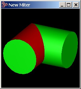
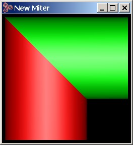
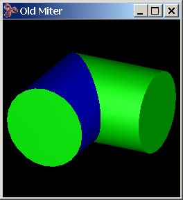
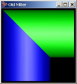
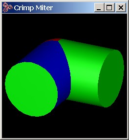
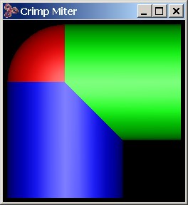
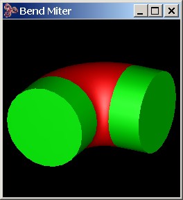
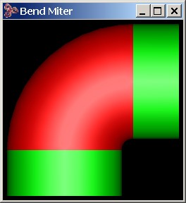
Figure. Sweep Miter Options
[Top]
© 1989-2007 Spatial Corp., a Dassault Systèmes company. All rights reserved.