Lofting
Lofting interpolates a surface through a given set of curves. The curves provide the u parameter of the resulting surface. The v parameter is computed and generated by the lofting algorithm. This technique allows the formation of relatively complex surfaces from a set of cross sectional curves. Lofting has been widely used for decades in the shipbuilding, automotive, and aircraft industries.
Lofting controls how the surface will pass through the set of input curves by controlling the magnitudes and directions of the tangent vectors going into and out of each curve. These tangents are controlled by coedge surface tangents or laws. The following figure shows an example of lofting five wires (w0-w4) with wire w0 and w4 having tangent constraints.
ACIS laws are supported in the lofting API and Scheme interfaces. A vector field can be specified using a law to control the take-off vector on any coedge in the profile of a loft surface. Lofting surfaces that do not contain a surface or a law can be simplified.
In general, lofting:
- Supports surface creation between coedges of wires and surfaces
- Controls the take-off vector weight factors for the loft transitions
- Supports laws to define coedge tangency constraints
- Supports surface isoparametric or arc length parameterization
- Can align the direction of the cross section curves so that they are in the same direction as the first curve
- Supports twist and non-twist minimization of the cross-section
- Supports control of the take-off vector direction, perpendicular to the coedge or in the loft direction
- Supports guide curves v
- Can simplify the created surface to an analytical surface (planar, conical, spherical, or toroidal), if applicable
- Can create a closed or open solid body
Lofting Parameters
Scheme Extensions: section
C++ Data Structures: Loft_Connected_Coedge_List
A lofting operation requires two basic categories of parameters (arguments). The first category defines the profiles to be lofted plus information to control the tangents through the curves that the loft surface must follow. The second category defines optional parameters to control what type of object is formed as a result of the loft operation.
Profiles
The main API for lofting is api_loft_coedges. As input it takes a list of the C++ data structure Loft_Connected_Coedge_List. Each structure in the list corresponds to one lofting profile or cross section. This structure contains the following data items:
- The number of coedges in the lofting cross section
- An array of pointers to coedges that form a connected chain
- The lofting cross section orientation
- The take-off vector weight factor
- A list of laws associated with each coedge in the list (optional)
A minimum of two Loft_Connected_Coedge_Lists is required for each loft. If a closed solid body is required, at least three distinct Loft_Connected_Coedge_Lists must be provided. If the first and last of these lists are identical, a closed solid loft body is automatically constructed.
The ending point of any coedge in the list of connected coedges should be the starting point of the next coedge in the list, first and last coedges excepted. In other words, the coedges are ordered in the list as they appear next to each other in model space. There cannot be any gaps between adjacent coedges.
When the coedges in the list are associated with a surface, the cross section orientation uses REVBIT to set the direction "out of" or "into" the starting surface. The expression "out of" means that the lofted surface is going out of the given ending surface, while "into" means that the lofted surface is going into the ending surface. When lofting between two surfaces, the starting surface needs to have its REVBIT set to 0 (for "out of", the default) and the ending surface needs to have its REVBIT set to 1 (for "into"). When lofting between multiple surfaces, the first surface has its REVBIT set for 0, while all others are set for 1. When lofting between a surface and an edge, REVBIT for both can be 0. The orientation bit is ignored if laws are present.
Options
In addition to the coedge list, the main lofting API takes options to control the surface parameterization, coedge twist, coedge direction, take-off direction, simplification, and creation of a solid or closed body. See Skinning and Lofting Options for more information.
The take-off vector can be weighted to affect the shape of the loft. The following figure illustrates the effect of the take-off vector weight factor on lofting between two surfaces. If a small value for the take-off vector factor is used, the transition from the tangent to the lofted surface happens abruptly. If a large value is used, the transition from the tangent to the lofted surface happens more gradually. Extremely high weight values could result in excessive whipping in the lofted surface, or a self-intersecting surface.
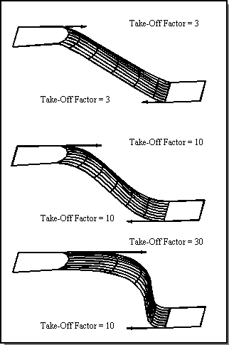
Figure. Take-Off Vector Factor
If desired, the skinning option estimate_loft_tanfacs can be set, which invokes an algorithm that finds an optimum factor to scale the weight for the tangent factors based on a minimum radius of curvature of the lofted body as a whole. This not only helps to create more pleasing surfaces but insures greater ability to shell and blend lofted models. If you set this option to TRUE, the user-supplied weight values in each Loft_Connected_Coedge_List are then scaled by the optimum scale factor found.
An array of law pointers is associated with each coedge in the coedge list. These vector laws are the tangency conditions of an edge. If a law is not used to control the tangency of an edge, its pointer should be NULL. In the case in which the law is NULL and the coedge has an associated surface than the surface conditions are used to control the tangency condition. If the Loft_Connected_Coedge_List has valid laws, than the laws take precedence over surface conditions.
Lofting Surfaces
Scheme Extensions: section, sheet:loft-wires
C++ APIs: api_loft_coedges
The curves used as input to the lofting function are given in terms of coedges. Since coedges can be associated with a face which contains surface information, tangent vectors from this surface can be used in defining the skin surface. These surface tangents associated with coedges are used with "tangent factors" to control magnitudes that define how the surface passes through a given input curve.
If a surface is used as a cross sectional curve, the surface determines the tangent of the skin surface when it meets the corresponding section.
The resulting sheet body consists of one or more faces linked together to form a shell. The loft surface is precise and does not have any internal C1/G1 discontinuities. The following figure shows an example of creating a lofted sheet body between two circular faces, one of which has a smaller diameter.
Scheme Example
| (option:set "cone_par" #t) (option:set "sil" #f) (option:set "u_par" 5) (option:set "v_par" 7) (define face1 (face:cylinder (position 0 0 0) (position 0 20 0) 40)) (define face2 (face:cylinder (position 0 50 0) (position 0 70 0) 50)) (zoom-all) (define coedges1 (entity:coedges face1)) (define coedges2 (entity:coedges face2)) (define section1 (section (list (list-ref coedges1 1)) #f 1)) (define section2 (section (list (list-ref coedges2 0)) #t 1)) (define sheet1 (sheet:loft-wires (list section1 section2))) |
Example. Lofting between Surfaces
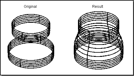
Figure. Lofting between Surfaces
Lofting with Laws
Scheme Extensions: section, law, sheet:loft-wires
C++ APIs: api_loft_coedges
An ACIS law can be associated with each of the input curves to control how the surface passes through the curve (coedge).
Laws are part of the lofting API and Scheme interfaces. Any vector field can be specified for the take-off vector for any or all of the coedges in the loft surface profiles. This type of surface control is frequently used to build aerospace type loft surfaces (for example, airfoils). The following figure shows an illustration of law vector fields.
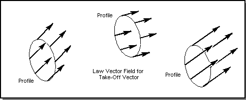
Figure. Law Vector Field
Scheme Example
| (part:clear) (option:set "u_par" 5) (option:set "v_par" 7) (define w1 (wire-body (edge:circular (position 0 0 0) 40 0 360))) (define w2 (wire-body (edge:circular (position 0 50 100) 40 0 360))) (define w3 (wire-body (edge:circular (position 0 0 200) 40 0 360))) (define law1 (law "vec(0,-.5,.5)")) (define dom1 (law "domain(law1,0,6.28)" law1)) (define law2 (law "vec(0,0,1)")) (define dom2 (law "domain(law1,0,6.28)" law2)) (define law3 (law "vec(0,.5,.5)")) (define dom3 (law "domain(law1,0,6.28)" law3)) (define c1 (entity:coedges w1)) (define sec1 (section c1 (list dom1) #f 200)) (define c2 (entity:coedges w2)) (define sec2 (section c2 (list dom2) #f 200)) (define c3 (entity:coedges w3)) (define sec3 (section c3 (list dom3) #f 200)) (define loft1 (sheet:loft-wires (list sec1 sec2 sec3))) |
Example. Lofting with Laws
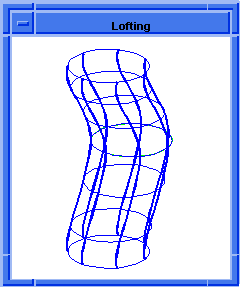
Figure. Lofting with Laws
Loft between Faces
Scheme Extensions: solid:loft-faces
C++ APIs: api_loft_faces
The api_loft_faces function is a higher-level feature for uniting two bodies using lofting. The bodies can be solid bodies or sheet bodies.
If one of the bodies is a solid, the operation is different than if it were a sheet body. In the case of a solid body, the face provided as an argument is removed from the body. Then, that face's peripheral edges are used to skin or loft to the peripheral edges of the second face. The result is one body.
If the body is a sheet body, the face provided as an argument is kept and serves as a cap of the resulting body. Here again, the face's peripheral edges are used to skin or loft to the peripheral edges of the second face.
Note: This does not check to see if the resulting body is self-intersecting.
In this API, lofting uses the surface information from the adjacent surfaces to determine the take-off vectors. Because this behavior is embedded inside the API it can not be changed. However, lofting between faces is simply a convenience function created from the standard lofting functionality. You could create lofting between faces functions that do permit changes to the take-off vector. The following figure illustrates lofting between two solid bodies.
Scheme Example
| ( option:set "sil" #t) ( option:set "u_par" 4) ( option:set "v_par" 5) (define block1 (solid:block (position 0 0 0) (position 10 10 10))) (define face_list1 (entity:faces block1)) (define block2 (solid:block (position 30 10 0) (position 40 20 10))) (define face_list2 (entity:faces block2)) (define loft1 (solid:loft-faces (list-ref face_list1 5) (list-ref face_list2 3) #f #t #t #f #f)) ( option:set "sil" #f) ( option:set "u_par" 0 ) ( option:set "v_par" 0 ) |
Example. Lofting Faces between Solid Bodies
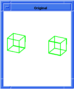
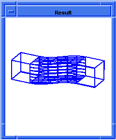
Figure. solid:loft-faces between Solid Bodies
Loft to a Point
Scheme Extensions: section, law, sheet:loft-wires
C++ APIs: api_loft_coedges
This example shows lofting from a square wire to a point. The point has a radial law take-off vector field defined, which caps the top smoothly. Each side of the square has a constant law take-off vector field defined (refer to the following figure).
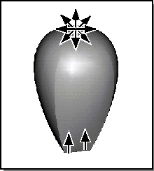
Figure. Lofting to a Point
Note: A law for the vector field is defined in general to go from R1 to R3. Before being applied to a section, this law needs to have its domain bounded.
Scheme Example
| (define v0 (wire-body:points (position 0 0 10))) (define v1 (wire-body:points (list (position 1 1 0) (position -1 1 0) (position -1 -1 0) (position 1 -1 0) (position 1 1 0) ))) (define coedge_list1 (entity:coedges v0)) (define coedge_list2 (entity:coedges v1)) (define lawa (law "vec(cos(t),sin(t),0)")) (define dom0 (law "domain(law1,law2,law3)" lawa (law:eval "0.0") (law:eval "2.0*Pi"))) (define lawb (law "vec(0,0,1)")) (define dom1 (law "domain(law1,0,1)" lawb)) (define sec1 (section coedge_list1 (list dom0) #f 20)) (define sec2 (section coedge_list2 (list dom1 dom1 dom1 dom1) #t 1)) (define loft1 (sheet:loft-wires (list sec1 sec2) #f #t #t #f)) (sheet:2d loft1) |
Example. Lofting to a Point
Loft to a Circle
Scheme Extensions: section, law, sheet:loft-wires
C++ APIs: api_loft_coedges
The following example shows a surface lofted from a square to a circle. The circle has a radial vector law field defined, while each side of the square has a constant law vector field defined (refer to the following figure).
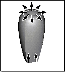
Figure. Lofting to a Circle
Scheme Example
| (define v1 (wire-body:points (list (position 1 1 0) (position -1 1 0) (position -1 -1 0) (position 1 -1 0) (position 1 1 0) ))) (define e0 (edge:circular (position 0 0 10) 1 0 360)) (define v0 (wire-body e0)) (define coedge_list1 (entity:coedges v0)) (define coedge_list2 (entity:coedges v1)) (define lawa (law "vec(cos(t),sin(t),0)")) (define dom0 (law "domain(law1,law2,law3)" lawa (law:eval "0.0") (law:eval "2.0*Pi"))) (define lawb (law "vec(0,0,1)")) (define dom1 (law "domain(law1,0,1)" lawb)) (define sec1 (section coedge_list1 (list dom0) #f 10)) (define sec2 (section coedge_list2 (list dom1 dom1 dom1 dom1) #t 1)) (define loft1 (sheet:loft-wires (list sec1 sec2) #t #t #t #f)) (sheet:2d loft1) (render) |
Example. Lofting to a Circle
Loft with Guides
Scheme Extensions: section, law, sheet:loft-wires-guides
C++ APIs: api_loft_coedges
Loft with Guides allows the designer to perform typical lofting operations with the additional constraint of one or more guide curves. In addition to Loft with Guides, guide curves can also be added to the vector and draft skinning operations
The rules pertaining to the guides follow those of skinning and further information can be reviewed in the Skinning with Guides section of Advanced Surfacing.
An additional skinning and lofting option "guide curve constraint" has been added to the skin options class to handle details of the Loft with Guide Curves operation. Guide curves can be placed on the profiles in any order or manner - although they must not intersect or cross. The tangent directions of the ends of the guide curves do not have to follow the loft surface tangent constraint however if they differ in direction the surface is said to be "over-constrained". (Refer to the following figure.) That is, at the exact same point, we have a guide curve directing the surface in one direction and a tangent constraint guiding the surface in a different direction.
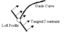
Figure. Over-constrained Surface Conditions
The "guide curve constraint" option is used to address this problem by telling the surface to prefer one constraint to the other. The two possible values of the option are "constrain_to_guide" and "constrain_to_tangent". As their names suggest the "constrain_to_guide" value will force the surface to follow the guide curve and ignore the tangent constraint in the region of the guide and the "constrain_to_tangent" will ignore the guide and constrain to the tangent cone in the region of the tangent cone. In order for the designer to get a surface matching exactly to the input given, he must give guide curves and tangent constraints that agree in direction
Scheme Example
|
(part:clear) (view:dl) (view:gl) (wcs (position 0 0 0) (gvector 1 0 0) (gvector 0 1 0)) (define w1 (wire-body (list (edge:linear (position 100 0 0) (position -100 0 0)) (edge:linear (position -100 0 0) (position -100 60 0)) (edge:circular-3pt (position -100 60 0) (position 0 110 0) (position 100 60 0)) (edge:linear (position 100 60 0) (position 100 0 0))))) (define w2 (wire-body (list (edge:linear (position 120 0 140) (position -120 0 140))(edge:linear (position -120 0 140) (position -120 60 140))(edge:circular-3pt (position -120 60 140) (position 0 150 140) (position 120 60 140))(edge:linear (position 120 60 140) (position 120 0 140))))) (define s1 (sheet:skin-wires (list w1 w2))) (entity:delete (list w1 w2)) (define w3 (wire-body (list (edge:linear (position 120 0 300) (position -120 0 300)) (edge:linear (position -120 0 300) (position -120 60 300)) (edge:circular-3pt (position -120 60 300) (position 0 150 300) (position 120 60 300)) (edge:linear (position 120 60 300) (position 120 0 300))))) ; define the guides (define g1 (edge:spline (list (position 0 150 140) (position 0 180 275) (position 0 150 300)))) (define coedge_list1 (list (list-ref (entity:coedges s1) 4) (list-ref (entity:coedges s1) 6) (list-ref (entity:coedges s1) 0) (list-ref (entity:coedges s1) 2))) (define sec1 (section coedge_list1 #f 1)) (define coedge_list2 (entity:coedges w3)) (define sec2 (section coedge_list2 #t 1)) (define l1 (sheet:loft-wires-guides (list sec1 sec2) (list g1) (skin:options "perpendicular" #t "guidePreference" "constrain_to_tangent" "solid" #t))) (entity:delete (list w3 g1)) (bool:unite l1 s1) |
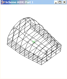
Figure. Lofting with Guide Curves
[Top]
© 1989-2007 Spatial Corp., a Dassault Systèmes company. All rights reserved.