Scheme Extensions Sli to Zz |
|
|
|
Technical Article |
| Scheme is a public domain programming
language, based on the LISP language, that uses an interpreter to run commands. ACIS
provides extensions (written in C++) to the native
Scheme language that can be used by an application to interact with ACIS through its
Scheme Interpreter. The C++ source files for ACIS
Scheme extensions are provided with the product. Spatial's Scheme based demonstration
application, Scheme ACIS Interface Driver Extension (Scheme AIDE), also uses these Scheme
extensions and the Scheme Interpreter.
|
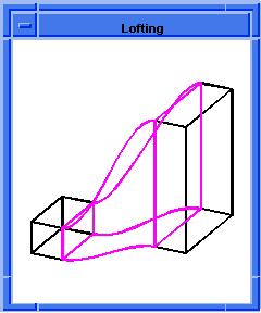
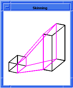
slinterface:show-mapping-curves
- Action
- Returns a list of edges that represent the mapping curves.
Filename- scm/scmext/skin/skin_scm.cpp
APIs- api_make_mapping_curves_sli
Syntax- (slinterface:show-mapping-curves interface [acis-opts])
Arg Types-
Returns- (edge ...)
Description
Returns a list of edges that represent the mapping curves. The edges are owned by the
caller and their responsibility to delete.
- Arguments
- interface is of SLInterface data type that is a data structure used to control skinning
and lofting operations.
acis-opts contains versioning and journaling information.
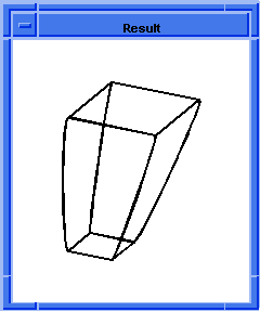
; slinterface:show-mapping-curves
; Build the wire bodies.
(define w1 (wire-body:points (list
(position 0 0 0) (position 0 2 0)
(position 1 3 0) (position 3 3 0)
(position 4 2 0) (position 4 0 0)
(position 0 0 0))))
;; w1
(define w2 (wire-body:points (list
(position 0 0 10) (position 0 3 10)
(position 4 3 10) (position 4 0 10)
(position 0 0 10))))
;; w2
; Get the coedges off the wire.
(define coedges1 (entity:coedges w1))
;; coedges1
(define coedges2 (entity:coedges w2))
;; coedges2
; Make sections from the coedges.
(define section1 (section coedges1 #f 1))
;; section1
(define section2 (section coedges2 #t 1))
;; section2
(define mySect (list section1 section2))
;; mySect
; Make the lofting interface.
(define myInterface
(slinterface:lofting mySect))
;; myInterface
(define loftingWires (slinterface:wires myInterface))
;; loftingWires
; Align and minimize twist.
(slinterface:align-wires myInterface)
;; #t
(slinterface:minimizetwist-wires myInterface)
;; #t
; Make two mapping curves.
(define positionList (list
(position 1 3 0) (position 0 3 10)))
;; positionList
(slinterface:mapping-curve myInterface positionList)
;; #t
(define positionList (list
(position 3 3 0) (position 4 3 10)))
;; positionList
(slinterface:mapping-curve myInterface positionList)
;; #t
; breakup the wires based on the new mapping curves
(slinterface:breakup-wires myInterface)
;; #t
; Show the mapping curves.
(define myCurves
(slinterface:show-mapping-curves myInterface))
;; myCurves
; Delete the curves.
(entity:delete myCurves)
;; ()
; Delete the interface.
(slinterface:delete-interface myInterface)
;; #t |
[Top]
slinterface:simplify-wires
- Action
- Removes the G1 vertices from the intermediate wire profiles.
Filename- scm/scmext/skin/skin_scm.cpp
APIs- api_simplify_wires_sli
Syntax- (slinterface:simplify-wires interface [acis-opts])
Arg Types-
Returns- boolean
Description
Removes the G1 vertices of the intermediate wire profiles by merging the adjacent
coedges/edges. This reduces the coedge/edge count which reduces the amount of surfaces and
eliminates near tangent edges which improves blending and shelling.
- Arguments
- interface is of SLInterface data type that is a data structure used to control skinning
and lofting operations.
acis-opts contains versioning and journaling information.
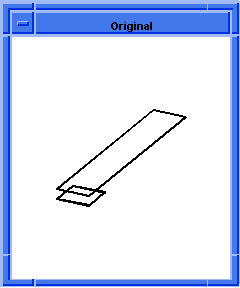
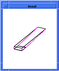
; slinterface:simplify-wires
; Create the geometry to illustrate this command.
; Create a wire body from list of edges.
(define wire_1 (wire-body (list
(edge:circular (position 0 0 0) 10 180 270)
(edge:linear (position 0 -10 0)
(position 100 -10 0))
(edge:circular (position 100 0 0) 10 270 360)
(edge:linear (position 110 0 0)
(position 110 25 0))
(edge:circular (position 100 25 0) 10 0 90)
(edge:linear (position 100 35 0)
(position 0 35 0))
(edge:circular (position 0 25 0) 10 90 180)
(edge:linear (position -10 25 0 )
(position -10 0 0)))))
;; wire_1
; Create some law scheme data types.
(define dom1
(law "domain (vec (0, 0, 1), -3.14, -1.57)"))
;; dom1
(define dom2 (law "domain (vec (0, 0, 1), 0, 100) "))
;; dom2
(define dom3
(law "domain (vec (0, 0, 1), -1.57, 0)"))
;; dom3
(define dom4 (law "domain (vec (0, 0, 1), 0, 25)"))
;; dom4
(define dom5 (law "domain (vec (0, 0, 1), 0, 1.57)"))
;; dom5
(define dom6 (law "domain (vec (0, 0, 1), 0, 100)"))
;; dom6
(define dom7
(law "domain (vec (0, 0, 1), 1.57, -3.14)"))
;; dom7
(define dom8 (law "domain (vec(0, 0, 1), 0, 25)"))
;; dom8
; Combine the laws.
(define laws1
(list dom1 dom2 dom3 dom4 dom5 dom6 dom7 dom8))
;; laws1
; Create the 2nd wire body.
(define wire_2 (wire-body (list (edge:circular
(position 40 5 30) 10 180 270)
(edge:linear (position 40 -5 30)
(position 60 -5 30))
(edge:circular (position 60 5 30) 10 270 360)
(edge:linear (position 70 5 30)
(position 70 20 30))
(edge:circular (position 60 20 30) 10 0 90)
(edge:linear (position 60 30 30)
(position 40 30 30))
(edge:circular (position 40 20 30) 10 90 180)
(edge:linear (position 30 20 30 )
(position 30 5 30)))))
;; wire_2
; Create the 2nd set of laws and combine them.
(define dom1
(law "domain (vec (0, 0, 1), -3.14, -1.57)"))
;; dom1
(define dom2 (law "domain (vec (0, 0, 1), 0, 15)"))
;; dom2
(define dom3
(law "domain (vec (0, 0, 1), -1.57, 0)"))
;; dom3
(define dom4 (law "domain (vec (0, 0, 1), 0, 25)"))
;; dom4
(define dom5 (law "domain (vec (0, 0, 1), 0, 1.57)"))
;; dom5
(define dom6 (law "domain (vec (0, 0, 1), 0, 15)"))
;; dom6
(define dom7
(law "domain (vec (0, 0, 1), 1.57, -3.14)"))
;; dom7
(define dom8 (law "domain (vec (0, 0, 1), 0, 25)"))
;; dom8
(define laws2
(list dom1 dom2 dom3 dom4 dom5 dom6 dom7 dom8))
;; laws2
; Create the work coordinate system.
(define my_wcs1 (wcs (position 0 0 0) (gvector 1 0 0)
(gvector 0 0 1)))
;; my_wcs1
; Set the work coordinate system to my_wcs1.
(wcs:set-active my_wcs1)
;; ()
; Create the 3rd wire body.
(define wire_3 (wire-body (list (edge:circular
(position 50 70 60) 20 0 360))))
;; wire_3
; Reset the wcs to it's initial state of inactive.
(wcs:set-active #f)
;; ()
; Define another law.
(define dom1
(law "domain (vec (0, -1, 0), 0.0, 3.14)"))
;; dom1
(define laws3 (list dom1))
;; laws3
; Get the coedges from wirebodies 1, 2, and 3.
(define coedges1 (entity:coedges wire_1))
;; coedges1
(define coedges2 (entity:coedges wire_2))
;; coedges2
(define coedges3 (entity:coedges wire_3))
;; coedges3
; Create a data structure.
(define section1 (section coedges1 laws1 #f 100))
;; section1
(define section2 (section coedges2 laws2 #f 50))
;; section2
(define section3 (section coedges3 laws3 #t 200))
;; section3
(define mySect (list section1 section2 section3))
;; mySect
; Create the lofting interface structure.
(define interface (slinterface:lofting
(list section1 section2 section3) "solid" #f))
;; interface
; Make all the contortions for the interface.
(slinterface:align-wires interface)
;; #t
(slinterface:minimizetwist-wires interface)
;; #t
; Remove the GI vertices from the intermediate wire
; profiles.
(slinterface:simplify-wires interface)
;; #t
(slinterface:breakup-wires interface)
;; #t
; Build the lofted body.
(define body (slinterface:build-body interface))
;; body
; Delete the lofted interface.
(slinterface:delete-interface interface)
;; #t
; Delete the defined list of entities.
(entity:delete (list wire_1 wire_2 wire_3))
;; ()
; Check the data structure, topology, and geometry.
(entity:check body 20)
; checked:
; 1 lumps
; 1 shells
; 0 wires
; 1 faces
; 1 loops
; 4 coedges
; 3 edges
; 2 vertices
;; ()
; Create a solid body from the sheet.
(define thicken (shell:sheet-thicken body -3))
;; thicken
; Find the position of the vertex.
(define pos (vertex:position (list-ref
(entity:vertices body) 2)))
;; pos
; Do the entity-to-entity blend.
(define ent (abl:ent-ent-blend (list-ref
(entity:faces body) 2)
(list-ref (entity:faces body) 1)
(abl:const-rad 0.5) pos #t))
;; ent
; Create a blend on the edges and vertices listed.
(define blend (blend:network body))
;; blend
; Make a cylindrical blend on the list of edges.
(define bledges (solid:blend-edges (list-ref
(entity:edges body) 7) 0.5))
;; bledges |
[Top]
slinterface:skin-guide
- Action
- Adds a guide curve to the skinning data structure.
Filename- scm/scmext/skin/skin_scm.cpp
APIs- api_add_guide_curve_si
Syntax- (slinterface:skin-guide interface edge [acis-opts])
Arg Types-
Returns- boolean
Description
Adds a guide curve to the skinning interface. Guide curves can be placed on the
skinning profiles and the surface will follow, exactly, that curve.
- Arguments
- interface is of SLInterface data type that is a data structure used to control skinning
and lofting operations.
edge gives the edge of the data structure.
acis-opts contains versioning and journaling information.
; slinterface:skin-guide
; Make the wire bodies.
(define wire-1 (wire-body (list
(edge:circular (position 0 0 0) 5 0 360))))
;; wire-1
(define wire-2 (wire-body
(edge:circular (position 0 0 70) 5 0 360)))
;; wire-2
(define myWires (list wire-1 wire-2))
;; myWires
; Make the guides.
(define guide1
(edge:linear (position 5 0 0) (position 5 0 70)))
;; guide1
(define guide2 (edge:spline (list
(position 0 5 0) (position 0 5 8)
(position 0 6 16) (position 0 3 24)
(position 0 6 32) (position 0 3 40)
(position 0 6 48) (position 0 3 54)
(position 0 9 62) (position 0 5 70))))
;; guide2
(define guide3 (edge:linear
(position 0 -5 0) (position 0 -5 70)))
;; guide3
(define guide4 (edge:linear
(position -5 0 0) (position -5 0 70)))
;; guide4
; Make the interactive interface.
(define myInterface
(slinterface:skinning myWires))
;; myInterface
; Align, do a minimize twist, and breakup the
; temporary lofting wires.
(slinterface:align-wires myInterface)
;; #t
(slinterface:minimizetwist-wires myInterface)
;; #t
(slinterface:breakup-wires myInterface)
;; #t
; Add the guides to the interface.
(slinterface:skin-guide myInterface guide1)
;; #t
(slinterface:skin-guide myInterface guide2)
;; #t
(slinterface:skin-guide myInterface guide3)
;; #t
(slinterface:skin-guide myInterface guide4)
;; #t
; Build the body.
(define myBody (slinterface:build-body myInterface))
;; myBody
(slinterface:delete-interface myInterface)
;; #t |
[Top]
slinterface:skinning
- Action
- Creates a skinning interface structure.
Filename- scm/scmext/skin/skin_scm.cpp
APIs- api_create_si
Syntax- (slinterface:skinning body-list [options] [acis-opts])
Arg Types-
Returns- SLInterface
Description
Creates a skinning interface data structure. The data structure is used as input to the
additional skinning API's each performing some stage of the skinning operation.
- Arguments
- body-list gives the list of wire bodies.
skin-options gives the different options available for skinning. For a complete
list of skinning options, refer to the skin:options documentation.
acis-opts contains versioning and journaling information.
; slinterface:skinning
; Build the wire bodies to be skinned.
(define wire-0 (wire-body (list
(edge:linear (position 0 0 0)
(position 50 0 0))
(edge:linear (position 50 0 0)
(position 50 50 0))
(edge:linear (position 50 50 0)
(position 0 50 0))
(edge:linear (position 0 50 0)
(position 0 0 0)))))
;; wire-0
(define wire-1 (wire-body (list
(edge:linear (position 0 0 100)
(position 50 0 100))
(edge:linear (position 50 0 100)
(position 50 50 100))
(edge:linear (position 50 50 100)
(position 0 50 100))
(edge:linear (position 0 50 100)
(position 0 0 100)))))
;; wire-1
(define myWires (list wire-0 wire-1))
;; myWires
; Build the skinning interface.
(define myInterface
(slinterface:skinning myWires))
;; myInterface
(define skinningWires
(slinterface:wires myInterface))
;; skinningWires
; Align, minimize twist, and breakup the wires.
(slinterface:align-wires myInterface)
;; #t
(slinterface:minimizetwist-wires myInterface)
;; #t
(slinterface:breakup-wires myInterface)
;; #t
; Build the body and delete the interface.
(define myBody (slinterface:build-body myInterface))
;; myBody
(slinterface:delete-interface myInterface)
;; #t
; Zoom to see the whole model
(define zoom (zoom-all))
;; zoom |
[Top]
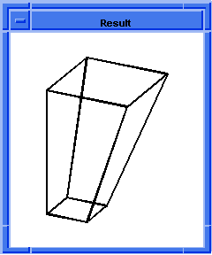
slinterface:skinning-draft
- Action
- Creates a skinning interface structure. Applies a take-off vector corresponding
to the draft angles.
Filename- scm/scmext/skin/skin_scm.cpp
APIs- api_create_si
Syntax- (slinterface:skinning-draft body-list angle1 angle2
magnitude1 magnitude2 [options] [acis-opts])
Arg Types-
Returns- SLInterface
Description
Creates a skinning interface data structure. The data structure is used as input to the
additional skinning APIs which perform some stages of the skinning operation.
- Arguments
- body-list is a list of wire bodies.
angle1 and angle2 give the draft angles.
The optional arguments magnitude1 and magnitude2 define the weight of the generated
take-off vectors.
skin-options gives the different options available for skinning. For a complete list of skinning options, refer to the skin:options documentation.
The acis-opts, which contain versioning and journaling parameters, must be the last
argument, if stated.
; slinterface:skinning-draft
; Build the wire bodies to be skinned.
(define wire-0 (wire-body (list
(edge:linear (position 0 0 0)
(position 50 0 0))
(edge:linear (position 50 0 0)
(position 50 50 0))
(edge:linear (position 50 50 0)
(position 0 50 0))
(edge:linear (position 0 50 0)
(position 0 0 0)))))
;; wire-0
(define wire-1 (wire-body (list
(edge:linear (position 0 0 100)
(position 50 0 100))
(edge:linear (position 50 0 100)
(position 50 50 100))
(edge:linear (position 50 50 100)
(position 0 50 100))
(edge:linear (position 0 50 100)
(position 0 0 100)))))
;; wire-1
(define myWires (list wire-0 wire-1))
;; myWires
; Build the skinning interface.
(define myInterface
(slinterface:skinning-draft
myWires 30 30 100 100))
;; myInterface
(define skinningWires
(slinterface:wires myInterface))
;; skinningWires
; Align, minimize twist, and breakup the wires.
(slinterface:align-wires myInterface)
;; #t
(slinterface:minimizetwist-wires myInterface)
;; #t
(slinterface:breakup-wires myInterface)
;; #t
; Build the body and delete the interface.
(define myBody (slinterface:build-body myInterface))
;; myBody
(slinterface:delete-interface myInterface)
;; #t
; Zoom to see the whole model
(zoom-all)
;; #[view 1180850] |
[Top]
slinterface:skinning-normal
- Action
- Creates a skinning interface structure. Applies a take-off vector normal to the
plane of the wire profile.
Filename- scm/scmext/skin/skin_scm.cpp
APIs- api_create_si
Syntax- (slinterface:skinning-normal body-list [normals] [options] [acis-opts])
Arg Types-
Returns- SLInterface
Description
Creates a skinning interface data structure. The data structure is used as input to the
additional skinning API's each performing some stage of the skinning operation.
- Arguments
- body-list is a list of wire bodies.
normals is a string that has four values, "first_normal",
"last_normal", "ends_normal" and "all_normal". These values
specify which profiles the normal constraint should be applied to. In the case of
"first_normal" the constraint is only applied to the first profile. Other
values, follow similarly.
options give the different options available for skinning. For a complete list of
skinning options, refer to the skin:options
documentation.
The acis-opts, which contain versioning and journaling parameters, must be the last
argument, if stated.
; slinterface:skinning-normal
; Build the wire bodies to be skinned.
(define wire1 (wire-body (list
(edge:circular (position 0 0 0) 10 180 270)
(edge:linear (position 0 -10 0)
(position 100 -10 0))
(edge:circular (position 100 0 0) 10 270 360)
(edge:linear (position 110 0 0)
(position 110 25 0))
(edge:circular (position 100 25 0) 10 0 90)
(edge:linear (position 100 35 0)
(position 0 35 0))
(edge:circular (position 0 25 0) 10 90 180)
(edge:linear (position -10 25 0 )
(position -10 0 0)))))
;; wire1
(define wire2 (wire-body (list
(edge:circular (position 40 5 30) 10 180 270)
(edge:linear (position 40 -5 30)
(position 60 -5 30))
(edge:circular (position 60 5 30) 10 270 360)
(edge:linear (position 70 5 30)
(position 70 20 30))
(edge:circular (position 60 20 30) 10 0 90)
(edge:linear (position 60 30 30)
(position 40 30 30))
(edge:circular (position 40 20 30) 10 90 180)
(edge:linear (position 30 20 30 )
(position 30 5 30)))))
;; wire2
(define my_wcs1 (wcs (position 0 0 0) (gvector 1 0 0)
(gvector 0 0 1)))
;; my_wcs1
(wcs:set-active my_wcs1)
;; ()
(define wire3 (wire-body (list
(edge:circular (position 50 70 60) 20 0 360))))
;; wire3
(wcs:set-active #f)
;; ()
(define interface (slinterface:skinning-normal
(list wire1 wire2 wire3) "all_normal"
"solid" #f))
;; interface
(slinterface:align-wires interface)
;; #t
(slinterface:minimizetwist-wires interface)
;; #t
(slinterface:breakup-wires interface)
;; #t
(slinterface:simplify-wires interface)
;; #t
(define body (slinterface:build-body interface))
;; body
(slinterface:delete-interface interface)
;; #t
(define thicken (shell:sheet-thicken body -2))
;; thicken |
[Top]
slinterface:skinning-options
- Action
- Resets the options in a skinning interface structure.
Filename- scm/scmext/skin/skin_scm.cpp
APIs- api_set_options_si
Syntax- (slinterface:skinning-options
interface [[options] |
[arc-length=#f [arc-length=#f [no-twist=#f
[align-directions=#f [simplify=#f
[closed=#f [solid=#t [periodic=#f
[virtualGuides=#f allow_same_uv=#f
[acis-opts] ]]]]]]]]]])
Arg Types-
Returns- boolean
Description
Resets the options in a skinning interface structure
- Arguments
- interface is of SLInterface datatype that is a data structure used to control skinning and lofting operations.
options gives the different options available for skinning.
The arc-length option is used to choose arc length or isoparametric parameterization of the skinning surfaces. For isoparametric
parameterization, the surface parameter in the V direction follows the cross
section curves. For arc length parameterization, the surface parameter follows
lines of constant length. The default is isoparametric parameterization.
Surfaces resulting from skinning with guide curves support isoparametric
parameterization only. The default is FALSE.
The no-twist option may be used to minimize the twist of the surface produced. Twist minimization aligns closed
curves such that the start of the second curve is aligned to the start of the
first curve. Even if a body's shape is unaffected by twisting, a surface with a
twist could produce unexpected results when faceting and rendering. The default
is TRUE.
The align-directions option is used to align the direction of the cross section curves such that the normal of
the first profile points towards the second profile. All other profiles are
aligned to follow the first and second. If the sections are not oriented in the
same direction, the align option should be used to avoid producing a twisted,
self intersecting body. The default is TRUE.
The simplify option simplifies the surface to a conical surface, if applicable. If all of the cross sections lie
on a conical surface (plane, cylinder, cone, sphere, or torus), the conical
surface is created instead. The SPAresabs
variable is used to determine whether
or not the cross section lies on a conical surface. The default is TRUE.
The closed option may be used when
the user needs to construct a solid body closed in V. (i.e., a torus). A solid
body will be constructed only when all the wires supplied are closed. At least
three profiles must be provided to create a closed body. The default is FALSE.
The solid option may be used when
a solid loft must be constructed but a closed body is not desired. When a
closed body is not desired, the end wires are capped with planar faces. The
default is TRUE.
The periodic option allows the construction of loft bodies that are periodic in V,i.e., bodies that close back on themselves smoothly
(continuously) at the start and end profiles. This option is activated in the
skinning APIs by giving the closed option a value of 2. In Scheme, this is
achieved by setting the periodic flag to TRUE. As for the closed option, at
least three profiles must be supplied to create a periodic loft body. The
default is FALSE.
The virtualGuides option may be used in order to have the user defined guides affect the body in a global
nature. The default is FALSE.
acis-opts contains versioning and journaling information.
; slinterface:skinning-options
; Build the wire bodies to be skinned.
(define wire-0 (wire-body (list
(edge:linear (position 0 0 0)
(position 50 0 0))
(edge:linear (position 50 0 0)
(position 50 50 0))
(edge:linear (position 50 50 0)
(position 0 50 0))
(edge:linear (position 0 50 0)
(position 0 0 0)))))
;; wire-0
(define wire-1 (wire-body (list
(edge:linear (position 0 0 100)
(position 50 0 100))
(edge:linear (position 50 0 100)
(position 50 50 100))
(edge:linear (position 50 50 100)
(position 0 50 100))
(edge:linear (position 0 50 100)
(position 0 0 100)))))
;; wire-1
(define myWires (list wire-0 wire-1))
;; myWires
; Build the skinning interface.
(define myInterface
(slinterface:skinning myWires))
;; myInterface
; Set new options for the interface.
(slinterface:skinning-options myInterface)
;; #f |
[Top]
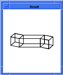
slinterface:skinning-ruled
- Action
- Creates a skinning interface structure. Sets a flag such that the resulting skin
body will consist of ruled surfaces.
Filename- scm/scmext/skin/skin_scm.cpp
APIs- api_create_si
Syntax- (slinterface:skinning-ruled body-list options [acis-opts])
Arg Types-
Returns- SLInterface
Description
Creates a skinning interface data structure. The data structure is used as input to the
additional skinning API's each performing some stage of the skinning operation.
- Arguments
- body-list gives the list of wire bodies.
options gives the different options available for skinning. For a complete list of skinning
options, refer to the skin:options documentation.
The acis-options, which contain versioning and journaling parameters, must be
the last argument, if stated.
; slinterface:skinning-ruled
; create four wire-bodies
(define wire1 (wire-body (list
(edge:circular (position 0 0 0) 30))))
;; wire1
(define wire2 (wire-body
(list (edge:circular (position 0 0 50) 30))))
;; wire2
(define wire3 (wire-body
(list (edge:circular (position 0 0 75) 50))))
;; wire3
(define wire4 (wire-body
(list (edge:circular (position 0 0 100) 50))))
;; wire4
(define interface (slinterface:skinning-ruled
(list wire1 wire2 wire3 wire4)))
;; interface
(slinterface:align-wires interface)
;; #t
(slinterface:minimizetwist-wires interface)
;; #t
(slinterface:breakup-wires interface)
;; #t
(slinterface:simplify-wires interface)
;; #t
(define body (slinterface:build-body interface))
;; body
(slinterface:delete-interface interface)
;; #t |
[Top]
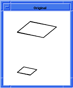
slinterface:skinning-vectors
- Action
- Creates a skinning interface structure. Applies a take-off vectors.
Filename- scm/scmext/skin/skin_scm.cpp
APIs- api_create_si
Syntax- (slinterface:skinning-vectors body-list SPAvector-list
[magnitude-list] [options] [acis-opts])
Arg Types-
Returns- SLInterface
Description
This function creates a skinning interface data structure. The data structure is used
as input to the additional skinning API's each performing some stage of the skinning
operation.
- Arguments
- The wires provided in the body-list argument, define the cross-sections to be
interpolated by the resulting sheet body. There must be at least two wire bodies.
The wire bodies are assumed to be simple, meaning only the first wire of each
body is used for skinning. The wires can be open or closed. The wires are copies,
i.e., the originals remain. The wires can share end points and do not have to
be C1 continuous tangent.
As additional constraints' take-off vectors can be supplied for each of the
profiles using the vector-list argument, the number of vectors provided has to
equal the number of profiles. A profile is interpolated without constraint if
the vector supplied for it is the zero vector.
magnitude-list is a list of real values for the magnitude.
options give the different values available for skinning.For a complete list of skinning
options, refer to the skin:options documentation.
acis-opts contains versioning and journaling information.
[Top]
slinterface:wires
- Action
- Returns the temporary wires from the skinning or lofting interface.
Filename- scm/scmext/skin/skin_scm.cpp
APIs- None
Syntax- (slinterface:wires interface [acis-opts])
Arg Types-
Returns- (wire-body ...)
Description
Returns the list of temporary wires used in the skinning or lofting operation. The
temporary wires will be deleted when the skinning/lofting interface is deleted.
- Arguments
- interface is of SLInterface datatype that is a data structure used to control skinning
and lofting operations.
acis-opts contains versioning and journaling information.
; slinterface:wires
; Build the wire bodies to be skinned.
(define wire-0 (wire-body (list
(edge:linear (position 0 0 0)
(position 50 0 0))
(edge:linear (position 50 0 0)
(position 50 50 0))
(edge:linear (position 50 50 0)
(position 0 50 0))
(edge:linear (position 0 50 0)
(position 0 0 0)))))
;; wire-0
(define wire-1 (wire-body (list
(edge:linear (position 0 0 100)
(position 50 0 100))
(edge:linear (position 50 0 100)
(position 50 50 100))
(edge:linear (position 50 50 100)
(position 0 50 100))
(edge:linear (position 0 50 100)
(position 0 0 100)))))
;; wire-1
(define myWires (list wire-0 wire-1))
;; myWires
; Build the skinning interface.
(define myInterface
(slinterface:skinning myWires))
;; myInterface
(define skinningWires
(slinterface:wires myInterface))
;; skinningWires
; Align, minimize twist, and breakup the wires.
(slinterface:align-wires myInterface)
;; #t
(slinterface:minimizetwist-wires myInterface)
;; #t
(slinterface:breakup-wires myInterface)
;; #t
; Build the body and delete the interface.
(define myBody (slinterface:build-body myInterface))
;; myBody
(slinterface:delete-interface myInterface)
;; #t
; Zoom to see the whole model.
(define zoom (zoom-all))
;; zoom |
[Top]
solid:loft-faces
- Action
- Unites two bodies by lofting between two faces.
Filename- scm/scmext/skin/skin_scm.cpp
APIs- api_loft_faces
Syntax- (solid:loft-faces
face0 [take-off-factor0=3.0]
face1 [take-off-factor1=3.0]
[skin-options] | [acis-opts])
Arg Types-
Returns- body
Description
When a solid is lofted, the face provided as an argument is removed from the body.
(This is one of the differences between lofting between solids and sheets.) Peripheral
edges from the first face are used to skin the peripheral edges of the second face. The
result is one body. However, this command does not conduct a self-intersect check on that
body. (Refer to Limitations below.)
Lofting uses the surface information from the adjacent surfaces to determine take-off
vectors. (Take-off vectors are pre-established and cannot be changed.) Skinning does not
use take-off vectors.
When ACIS makes a BODY
from a FACE
using api_loft_faces, it creates a single-sided face
body. A single-sided face body is really a solid, not a sheet (infinitely thin) body. When
a face body is single-sided, basic solid modeling concepts (and ACIS) consider the body to
be a solid which extends from the back side of the face out to infinity with ill defined
boundaries extending where the edges of the original face extend backward. The way in
which the single-sided face body is used determines whether subsequent operations, such as
Booleans, work properly.
- Arguments
- face0 and face1 are the input arguments that are removed during lofting.
take-off-factor0 and take-off-factor1 is applied to the magnitude of the take-off
vectors, and can be used to control the shape of the loft surface.
skin-options gives the different options available for skinning.For a complete list of
skinning options, refer to the skin:options
documentation.
acis-opts contains versioning and journaling information.
Limitations- Does not check for self-intersecting bodies. For perpendicular to work properly
while set to #t, the perpendicular take-off vectors from the defining coedge cannot
intersect.
[Top]
solid:loft-faces-guides
- Action
- Unites two bodies by lofting between two faces with optional guide curves.
Filename- scm/scmext/skin/skin_scm.cpp
APIs- api_loft_faces
Syntax- (solid:loft-faces-guides
face0 [take-off-factor0=3.0]
face1 [take-off-factor1=3.0]
guides ...
[options] | [acis-opts])
Arg Types-
Returns- body
Description
When a solid is lofted, the face provided as an argument is removed from the body.
(This is one of the differences between lofting between solids and sheets.) Peripheral
edges from the first face are used to skin the peripheral edges of the second face. The
result is one body. However, this command does not conduct a self-intersect check on
that body. (Refer to Limitations below.)
Lofting uses the surface information from the adjacent surfaces to determine
take-off vectors. (Take-off vectors are pre-established and cannot be
changed.) Skinning does not use take-off vectors.
When ACIS makes a BODY
from a FACE
using api_loft_faces, it creates a single-sided
face body. A single-sided face body is really a solid, not a sheet (infinitely thin)
body. When a face body is single-sided, basic solid modeling concepts (and ACIS)
consider the body to be a solid which extends from the back side of the face out to
infinity with ill defined boundaries extending where the edges of the original face extend
backward. The way in which the single-sided face body is used determines whether
subsequent operations, such as Booleans, work properly.
- Arguments
- face0 and face1 are the input arguments that are removed during lofting.
take-off-factor0 and take-off-factor1 is applied to the magnitude of the take-off
vectors, and can be used to control the shape of the loft surface.
guides gives the list of guides.
skin-options gives the different options available for skinning.
For a complete list of skinning options, refer to the skin:options documentation.
acis-opts contains versioning and journaling information.
Limitations- Does not check for self-intersecting bodies. For perpendicular to work
properly while set to #t, the perpendicular take-off vectors from the defining coedge
cannot intersect.
; solid:loft-faces-guides
; Define the faces and guides
(wcs (position 0 0 0) (gvector 1 0 0)
(gvector 0 1 0))
;; #[entity 1 1]
(define wire1 (wire-body (list (edge:circular-3pt
(position 0 0 0) (position 5 2.5 0)
(position 10 0 0))
(edge:linear (position 10 0 0)
(position 10 -10 0))
(edge:linear (position 10 -10 0)
(position 0 -10 0))
(edge:linear (position 0 -10 0)
(position 0 0 0)))))
;; wire1
(sheet:planar-wire wire1)
;; #[entity 6 1]
(shell:sheet-thicken wire1 5)
;; #[entity 6 1]
(define guide (edge:spline (list (position 5 2.5 0)
(position 5 10 3.5) (position 5 20 2.5))
(gvector 0 1 0) (gvector 0 1 0)))
;; guide
(define body2 (solid:block (position 0 20 2.5)
(position 10 30 -2.5)))
;; body2
(define front_face1 (list-ref
(entity:faces wire1) 2))
;; front_face1
(define front_face2 (list-ref
(entity:faces body2) 2))
;; front_face2
;Apply lofting with the guides
(define final_body (solid:loft-faces-guides
front_face1 front_face2 (list guide)))
;; final_body |
[Top]
solid:skin-faces
- Action
- Creates a body that interpolates two faces.
Filename- scm/scmext/skin/skin_scm.cpp
APIs- api_skin_faces
Syntax- (solid:skin-faces face0 face1 [[options] |
[arc-length=#f] [no-twist=#t]
[align-directions=#t] [simplify=#t [acis-opts]]])
Arg Types-
Returns- body
Description
The edges of the given faces define the cross-sections to be interpolated by the
resulting sheet body. There must be at least two faces, but only one face from each body
is used.
- Arguments
- face0 and face1 are the input arguments that are removed during lofting.
options give the different options available for skinning. For a complete list of skinning
options, refer to the skin:options documentation.
acis-opts, which contains versioning and journaling information. must be
the last argument, if stated.
Limitations- Does not check for self-intersecting bodies. For perpendicular to work properly
while set to #t, the perpendicular take-off vectors from the defining coedge cannot
intersect.
[Top]
wire:get-net-curves-u
- Action
- Returns the list of u-direction curves underlying a skinned surface.
Filename- scm/scmext/skin/skin_scm.cpp
APIs- None
Syntax- (wire:get-net-curves-u face)
Arg Types-
Returns- (entity ...)
Description
This extension takes a face as an input argument. It retrieves all of the underlying u
direction curves of the face as wires. The wires are then converted to Scheme entities.
This entity list is then returned.
- Arguments
- face is an input entity of a Scheme Component.
; wire:get-net-curves-u
; Create a series of curves in the v direction.
(define v1 (list (position 0 0 0) (position 5 10 0)
(position 10 5 0) (position 15 15 0)
(position 20 0 0)))
;; v1
(define v2 (list (position 0 10 5) (position 5 5 5)
(position 10 15 5) (position 15 10 5)
(position 20 10 5)))
;; v2
(define v3 (list (position 0 20 10)
(position 5 15 10) (position 10 20 10)
(position 15 5 10) (position 20 20 10)))
;; v3
(define v4 (list (position 0 15 15)
(position 5 10 15) (position 10 15 15)
(position 15 0 15) (position 20 15 15)))
;; v4
; Create a series of curves in the u direction.
(define u1 (list (position 0 0 0) (position 0 10 5)
(position 0 20 10) (position 0 15 15)))
;; u1
(define u2 (list (position 10 5 0) (position 10 15 5)
(position 10 20 10) (position 10 15 15)))
;; u2
(define u3 (list (position 20 0 0) (position 20 10 5)
(position 20 20 10) (position 20 15 15)))
;; u3
(define v1 (wire-body (edge:spline v1)))
;; v1
(define v2 (wire-body (edge:spline v2)))
;; v2
(define v3 (wire-body (edge:spline v3)))
;; v3
(define v4 (wire-body (edge:spline v4)))
;; v4
(define u1 (wire-body (edge:spline u1)))
;; u1
(define u2 (wire-body (edge:spline u2)))
;; u2
(define u3 (wire-body (edge:spline u3)))
;; u3
; Create a sheet body that interpolates the series
; of wires defined above.
(define net1 (sheet:net-wires (list v1 v2 v3 v4)
(list u1 u2 u3) #t))
;; net1
; Make figure easier to view.
(define sheet (sheet:2d net1))
;; sheet
; Delete the u direction entities.
(entity:delete (list u1 u2 u3))
;; ()
; Delete the v direction entities.
(entity:delete (list v1 v2 v3 v4))
;; ()
; Return the list of u direction curves for the
; underlying skinned surface.
(define u-list (wire:get-net-curves-u
(car (entity:faces net1))))
;; u-list
; (#[entity 18 1] #[entity 19 1] #[entity 20 1]) |
[Top]
wire:get-net-curves-v
- Action
- Returns the list of v-direction curves underlying a skinned surface.
Filename- scm/scmext/skin/skin_scm.cpp
APIs- None
Syntax- (wire:get-net-curves-v face)
Arg Types-
Returns- (entity ...)
Description
This extension takes a face as an input argument. It retrieves all of the v
direction curves underlying the face as wires. The wires are then converted to Scheme
entities. This entity list is then returned.
- Arguments
- face is an input entity of a Scheme Component.
; wire:get-net-curves-v
; Example not available for this release
; Create a series of curves in the v direction.
(define v1 (list (position 0 0 0) (position 5 10 0)
(position 10 5 0) (position 15 15 0)
(position 20 0 0)))
;; v1
(define v2 (list (position 0 10 5) (position 5 5 5)
(position 10 15 5) (position 15 10 5)
(position 20 10 5)))
;; v2
(define v3 (list (position 0 20 10)
(position 5 15 10) (position 10 20 10)
(position 15 5 10) (position 20 20 10)))
;; v3
(define v4 (list (position 0 15 15)
(position 5 10 15) (position 10 15 15)
(position 15 0 15) (position 20 15 15)))
;; v4
; Create a series of curves in the u direction.
(define u1 (list (position 0 0 0) (position 0 10 5)
(position 0 20 10) (position 0 15 15)))
;; u1
(define u2 (list (position 10 5 0) (position 10 15 5)
(position 10 20 10) (position 10 15 15)))
;; u2
(define u3 (list (position 20 0 0) (position 20 10 5)
(position 20 20 10) (position 20 15 15)))
;; u3
(define v1 (wire-body (edge:spline v1)))
;; v1
(define v2 (wire-body (edge:spline v2)))
;; v2
(define v3 (wire-body (edge:spline v3)))
;; v3
(define v4 (wire-body (edge:spline v4)))
;; v4
(define u1 (wire-body (edge:spline u1)))
;; u1
(define u2 (wire-body (edge:spline u2)))
;; u2
(define u3 (wire-body (edge:spline u3)))
;; u3
; Create a sheet body that interpolates the series
; of wires defined above.
(define net1 (sheet:net-wires (list v1 v2 v3 v4)
(list u1 u2 u3) #t))
;; net1
; Make figure easier to view.
(define sheet (sheet:2d net1))
;; sheet
; Delete the u direction entities.
(entity:delete (list u1 u2 u3))
;; ()
; Delete the v direction entities.
(entity:delete (list v1 v2 v3 v4))
;; ()
; Return the list of v direction curves for the
; underlying skinned surface.
(define v-list (wire:get-net-curves-v
(car (entity:faces net1))))
;; v-list
v-list
;; (#[entity 18 1] #[entity 19 1] #[entity 20 1]
;; #[entity 21 1]) |
[Top]
wire:get-skin-curves
- Action
- Returns a list of curves underlying a skinned surface.
Filename- scm/scmext/skin/skin_scm.cpp
APIs- None
Syntax- (wire:get-skin-curves face)
Arg Types-
Returns- (entity ...)
Description
This extension takes a face as an input argument and retrieves all underlying curves of
the face as wires. The wires are converted into Scheme entities and the entity list is
returned.
- Arguments
- face is an input entity of a Scheme Component.
; wire:get-skin-curves
; Create the necessary geometry and
; get the skin curves.
(define wire_1 (wire-body (list
(edge:linear (position 0 0 0) (position 50 0 0))
(edge:linear (position 50 0 0)
(position 50 50 0))
(edge:linear (position 50 50 0)
(position 0 50 0))
(edge:linear (position 0 50 0)
(position 0 0 0)))))
;; wire_1
(define wire_2 (wire-body (list
(edge:linear(position 0 0 50) (position 50 0 50))
(edge:linear(position 50 0 50)
(position 50 50 50))
(edge:linear(position 50 50 50)
(position 0 50 50))
(edge:linear (position 0 50 50)
(position 0 0 50)))))
;; wire_2
(define body (sheet:skin-wires (list wire_1 wire_2)))
;; body
(define skinning-wires (wire:get-skin-curves (list-ref (entity:faces body) 4))
; set the skinning wires to red
(entity:set-color skinning-wires 1)
|
[Top]
© 1989-2007 Spatial Corp., a Dassault Systèmes company. All rights reserved.
![]()
![]()
