Interactive Interface
The interactive programming interface for skinning and lofting allows the application developer to call the individual steps performed in skinning and lofting one at a time to build an interactive skinning or lofting application. An interactive skinning or lofting application allows the end user more control of the skinned or lofted body by using guide curves, mapping curves, preview functions, tangent factors, and local control of profile vertices.
To facilitate this multi-function API, two classes are provided to maintain a "context" or state of the lofting/skinning operation. This state is passed as an object to each of the APIs. More specifically, the first API called is api_create_si for skinning, or api_create_li for lofting, which returns an AcisSLInterface object. This object maintains all the information and the state of the lofting or skinning operation. It is passed in as input to the other APIs and is deleted in the end with a call to api_delete_sli.
Interactive Interface Functions
The interactive interface is essentially the surfacing of more than 20 functions, which perform required or optional skinning and lofting steps.
The following list shows the required steps and their corresponding APIs.
-
Accept as input a list of wire bodies (in the case of skinning) or a loft
connected coedge list (in the case of lofting) and build a temporary set of
skinning/lofting wires.
api_create_si or api_create_li
-
Align this set of temp wires so that the wire normals are consistent. (This is
explained in detail with the align option.)
api_align_wires_sli
-
Perform a minimize twist on this set of temp wires so that a non-twisted
surface is created. (This is explained in detail with the minimize twist
option.)
api_minimize_twist_wires_sli
-
(Optional) Add a mapping curve.
api_add_mapping_curve_sli
-
(Optional) Add a guide curve.
api_add_guide_curve_si
-
Perform a breakup of the coedges of the set of temporary wires so that they all
have an equal number of coedges.
api_breakup_wires_sli
-
(Optional) Preview the edges of the lofted body.
api_build_edges_sli
-
(Optional) Locally modify the location of a non-corner vertex to control the
surface extents.
api_modify_wire_sli
-
Create surfaces stretched from coedge to coedge and stitch them to make a sheet
or solid body.
api_build_body_sli
-
Delete excess data.
api_delete_sli
The following group of APIs perform non-incremental optional functions such as adding guide curves, adding mapping curves, computing the tangent factors, and previewing edges.
The following APIs must be called from the interactive interface.
- api_align_wires_sli
- Aligns the directions of the wires in the skinning or lofting profiles.
- api_build_body_sli
- Builds the sheet body from the data in the lofting interface.
- api_breakup_wires_sli
- Creates an equal number of coedges in each wire of the skinning or lofting profiles.
- api_create_si
- Creates an AcisSkinningInterface object.
- api_create_li
- Creates an AcisLoftingInterface object.
- api_delete_sli
- Deletes an AcisSLInterface object.
- api_make_wires_sli
- Creates a set of broken up wires used for skinning or lofting.
- api_minimize_twist_wires_sli
- Aligns the start vertices of the wires in the skinning/lofting profiles.
The following APIs do not need to be called from the interactive interface.
- api_add_guide_curve_si
- Adds a guide curve to a set of skinning profiles.
- api_add_mapping_curve_sli
- Adds a guide curve to a set of skinning profiles.
- api_add_vertex_sli
- Adds a vertex to each wire in a list of wires.
- api_build_edges_sli
- Builds a list of edges that represent the extents of the surfaces if the wires or coedges were to be lofted or skinned.
- api_build_faces_sli
- Builds a list of skinning or lofting faces.
- api_clear_guide_curves_sli
- Clears the guide curves in the AcisSkinningInterface.
- api_clear_mapping_curves_sli
- Removes all the mapping curves from the AcisSLInterface.
- api_collapse_wires_sli
- Deletes a degenerate coedge in each wire of a list of wires.
- api_estimate_min_rad_curvature_skin
- Estimates the magnitude of the tangent vector field to build surfaces with a minimum radius of curvature.
- api_estimate_tangent_factor_scale_li
- Estimates the optimal magnitude to scale the takeoff vectors on the loft profile cross section.
- api_get_tangent_factors_li
- Gets the current set of tangent factors on the loft profiles.
- api_lose_surface_conditions_li
- Removes the surface conditions from the wires in the lofting profiles.
- api_make_mapping_curves_sli
- Gets a list of the mapping curves that currently exist in the AcisSLInterface.
- api_modify_wire_sli
- Modifies the position of a vertex on a coedge of a wire.
- api_remove_mapping_curve_sli
- Removes a mapping curve from the AcisSLInterface.
- api_remove_vertex_sli
- Removes a vertex from each wire in a list of wires.
- api_set_tangent_factors_li
- Sets the scale factors of the takeoff vectors for the lofting operation.
- api_start_vertex_sli
- Modifies which vertex in a loop of coedges forming a wire is the starting vertex for traversing the loop.
- api_valid_start_vertices_sli
- Gets a list of valid starting vertices for skinning or lofting.
Interactive Interface Examples
The following examples show skinning and lofting applications that can be written with the Interactive Interface. Each requires some form of user input in an intermediate step of skinning or lofting, hence requiring this multi-function (interactive) API.
Interactive Skinning with Guide Curves
Scheme Extensions: slinterface:skin-guide
C++ APIs: api_add_guide_curve_si
Scheme Example
| (part:clear) (define frame1 (wcs (position 0 0 0) (gvector 1 0 0) (gvector 0 1 0))) (define wire_0 (wire-body (list (edge:linear (position -60 0 0) (position 60 0 0)) (edge:linear (position 60 0 0) (position 60 50 0)) (edge:linear (position 60 50 0) (position -60 50 0)) (edge:linear (position -60 50 0) (position -60 0 0))))) (define wire_1 (wire-body (list (edge:linear (position -30 0 100) (position 30 0 100)) (edge:linear (position 30 0 100) (position 30 40 100)) (edge:linear (position 30 40 100)(position -30 40 100)) (edge:linear (position -30 40 100) (position -30 0 100))))) (define wire_3 (wire-body (list (edge:circular (position 0 -85 150) 25 0 360)))) (define guide1 (edge:spline (list (position 0 0 0) (position 0 20 50) (position 0 0 100) (position 0 -20 160) (position 0 -50 160) (position 0 -60 150)))) (zoom-all) (define interface (slinterface:skinning (list wire_0 wire_1 wire_3) #f #t #t #f #t #f #f #t)) (define skinningWires (slinterface:wires interface)) (entity:set-color skinningWires 1) (slinterface:align-wires interface) (slinterface:minimizetwist-wires interface) (slinterface:breakup-wires interface) (body:reverse (list-ref skinningWires 2)) (slinterface:skin-guide interface guide1) (define body (slinterface:build-body interface)) (slinterface:delete-interface interface) (entity:delete (list wire_0 wire_1 wire_3)) (solid:blend-edges (list-ref (entity:edges body) 8) 8) (solid:blend-edges (list-ref (entity:edges body) 4) 8) (solid:blend-edges (list-ref (entity:edges body) 13) 8) (solid:blend-edges (list-ref (entity:edges body) 7) 8) (shell:sheet-thicken body 3) |
Example. Skinning with Guide Curves
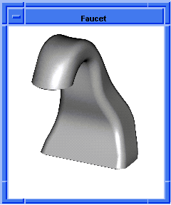
Figure. Skinning with Guide Curves
Mapping Curves with Skinning and Lofting
Scheme Extensions: slinterface:mapping-curve
C++ APIs: api_add_mapping_curve_sli
Mapping curves give the user the ability to control the breakup of skinning and lofting wires without constraining the surfaces. The following figure shows a set of vertices selected by the end user. After selection, the breakup algorithm guarantees alignment of those vertices.
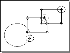
Figure. Circled Vertices Selected
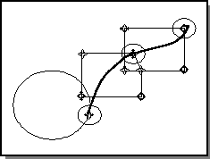
Figure. Edge Created from Mapping Curve
The user may select additional vertices to be aligned or may simply start the breakup code at this point. The breakup control of the mapping curves will be identical to the breakup control of the guide curves. For skinning, it is possible to add both mapping curves and guide curves to the same set of wire profiles.
A large degree of preprocessing is needed to validate the input of the mapping curves. The following limitations apply:
- A vertex can only be included in one mapping curve.
- Mapping curves cannot cross.
- A vertex on each wire profile must be designated.
- Vertices must be given in order, from the first wire to the last, or from the last to the first.
- No more than one vertex per wire per guide curve may be given.
The following figure shows the flow of control from user input to breakup. The mapping attributes are entity attributes that are placed on the vertices of the coedges and read by the breakup code.
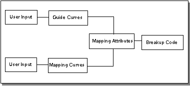
Figure. Flow of Control from User Input to Breakup
Scheme Example
| ; Wire-body 1 (part:clear) (define frame1 (wcs (position 0 0 0) (gvector 1 0 0) (gvector 0 1 0))) (define wire1 (edge:circular (position 0 0 0) 25 0 360)) (define wire2 (edge:circular (position 20 -20 0) 25 0 90)) (define wire3 (edge:circular (position 20 -20 0) 20 0 90)) (define twoEdges (edge:split wire2 (car (curve:intersect wire1 wire2)))) (entity:delete (cadr twoEdges)) (define twoEdges (edge:split wire3 (car (curve:intersect wire1 wire3)))) (entity:delete (cadr twoEdges)) (define twoEdges (edge:split wire1 (car (curve:intersect wire1 wire2)))) (entity:delete (car twoEdges)) (define wire1 (cadr twoEdges)) (define twoEdges (edge:split wire1 (car (curve:intersect wire1 wire3)))) (entity:delete (cadr twoEdges)) (define twoEdges (edge:split wire1 (car (curve:intersect wire1 wire3)))) (entity:delete (cadr twoEdges)) (define wire4 (edge:linear (edge:start wire2) (edge:start wire3))) (define wireBody1 (wire-body (list wire1 wire2 wire4 wire3))) ; Wire-body 2 (define wire1 (edge:circular (position 0 0 -60) 10 0 360)) (define wire2 (edge:circular (position 5 -23.5 -60) 25 65 90)) (define wire3 (edge:circular (position 5 -23.5 -60) 21 65 90)) (zoom-all) (define twoEdges (edge:split wire2 (car (curve:intersect wire1 wire2)))) (entity:delete (cadr twoEdges)) (define twoEdges (edge:split wire3 (car (curve:intersect wire1 wire3)))) (entity:delete (cadr twoEdges)) (define twoEdges (edge:split wire1 (car (curve:intersect wire1 wire2)))) (entity:delete (car twoEdges)) (define wire1 (cadr twoEdges)) (define twoEdges (edge:split wire1 (car (curve:intersect wire1 wire3)))) (entity:delete (cadr twoEdges)) (define twoEdges (edge:split wire1 (car (curve:intersect wire1 wire3)))) (entity:delete (cadr twoEdges)) (define wire4 (edge:linear (edge:start wire2) (edge:start wire3))) (define wireBody2 (wire-body (list wire1 wire2 wire4 wire3))) ; Start the skinning operation. (define interface (slinterface:skinning (list wireBody1 wireBody2))) (define skinningWires (slinterface:wires interface)) (entity:set-color skinningWires 0) (slinterface:align-wires interface) (slinterface:minimizetwist-wires interface) (define positionList (list (position 40 -20 0) (position 13.8749834965547 -4.46753647223035 -60))) (slinterface:mapping-curve interface positionList) (define positionList (list (position 45 -20 0) (position 15.5654565435175 -0.842305324083753 -60))) (slinterface:mapping-curve interface positionList) (slinterface:breakup-wires interface) (define body (slinterface:build-body interface)) (slinterface:delete-interface interface) |
Example. Mapping Curves
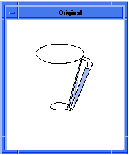
Figure. Mapping Curves
Estimating Tangent Factors for Lofting
Scheme Extensions: slinterface:get-tanfac-scale, slinterface:set-tan-facs
C++ APIs: api_estimate_tangent_factor_scale_li, api_set_tangent_factors_li
The Advanced Surfacing Component uses APIs and Scheme extensions to estimate the magnitude of weight factors.
Using APIs
Loft bodies can be shelled only to a thickness smaller than their minimum radius of curvature, api_estimate_min_rad_curvature_skin allows users to estimate the maximum possible shelling thickness. Also, edges of loft bodies cannot be filleted by blend radii that are larger than the minimum radius of curvature of the loft body. This API should also help users in selecting the appropriate blend radius for edges of loft bodies.
The api_estimate_tangent_factor_scale_li allows the user to estimate the magnitude of the take-off vectors on each of the loft profile cross-sections so that the resulting loft body has as large a minimum radius of curvature as possible. Maximizing the minimum radius of curvature should enable the loft bodies to be shelled to a greater thickness and their edges to be filleted with greater blend radii. It is important to note that this API provides a single scale factor that should be applied simultaneously to all take-off vectors.
There are four arguments to this API-one input and three outputs, the last two being optional. The input argument to this API is a pointer to an AcisLoftingInterface object. The outputs from the API are: (a) a range of reasonable values by which the take-off vectors may be scaled; (b) the optimum scale factor value in the range which maximizes the minimum radius of curvature and; (c) the minimum radius of curvature of the loft corresponding to the optimum scale factor. The typical use of this API is as follows:
-
Create an instance of AcisLoftingInterface using
api_create_li. The inputs to this API are the same as inputs
to
api_loft_coedges. A populated AcisLoftingInterface object
is created as a result.
-
Use
api_estimate_min_rad_curvature_skin to estimate the minimum
radius of curvature of the loft body.
-
If the minimum radius of curvature of the loft body is satisfactory then there
is no need to re-scale the magnitudes of the take-off vectors.
-
Otherwise, use
api_estimate_tangent_factor_scale_li to estimate a reasonable
range for the scale factor if that is sufficient, or estimate an optimal value
for the scale factor and the corresponding minimum radius of curvature of the
loft body.
-
Re-scale the tangent factors of the individual profiles by the scale factor
determined in Step 4.
-
Reset the new tangent factors of the wire profiles in the AcisLoftingInterface
object using
api_set_tangent_factors_li.
- Build the loft body using api_build_body_sli. The resulting loft body will have close to the largest minimum radius of curvature that is possible under the given law/surface constraints.
The API api_estimate_tangent_factor_scale_li is interfaced into Scheme through the Scheme extension slinterface:get-tanfac-scale. This Scheme extension takes as argument a slinterface object that describes the loft and a Boolean value. If the Boolean is true the API estimates a range of scale factor values and an optimal value for the scale factor in this range, otherwise (Boolean = false) it returns only a range of scale factor values. Consequently the API works faster when the Boolean is set to false.
The API api_estimate_min_rad_curvature_skin is interfaced into Scheme through the Scheme extension slinterface:min-rad. This Scheme extension takes as argument a slinterface object that describes the loft and returns the minimum radius of curvature of the loft body.
The tangent factors on the loft body may be reset at any time using the API api_set_tangent_factors_li or its equivalent Scheme extension slinterface:set-tan-facs. This Scheme extension takes as argument a slinterface object that describes the loft and the factor by which the weights on all the individual sections need to be scaled.
Using Scheme Extensions
Scheme Example
The following Scheme example demonstrates estimating the magnitude of the take-off vectors on two profiles.
| ; Construct a rectangular wire body. (define w1 (wire-body:points (list (position 0 0 0) (position 50 0 0) (position 50 50 0) (position 0 50 0) (position 0 0 0)))) ; Make a wire body from a single position. (define w2 (wire-body:points (list (position 0 0 75)))) ; Specify a normalized vector field along the z-axis. (define dom1 (law "DOMAIN (VEC (0,0,1),0,50)")) ; Get the list of coedges of wire 1. (define coedge1 (entity:coedges w1)) ; Apply the vector field to the edges of wire1. (define loft_wire1 (section coedge1 (list dom1 dom1 dom1 dom1) #t 1)) ; Get the list of coedges of wire 2. (define coedge2 (entity:coedges w2)) ; Define a normalized radial vector field in the xy - plane. (define dom2 (law "DOMAIN (-VEC (COS (X),SIN (X),0),0,6.28318530717959)")) ; Apply the vector field to the edges of wire 2. (define loft_wire2 (section coedge2 (list dom2 ) #t 1)) ; Combine the coedge lists together in one list. (define sect (list loft_wire1 loft_wire2 )) ; Set the following lofting options: ; arc_length = TRUE ; minimize_twist = TRUE ; align_directions = TRUE ; perpendicular = FALSE ; simplify = FALSE ; solid = FALSE ; closed = TRUE ; Define the lofting interface object using the coedge lists ; and the lofting options. (define interface (slinterface:lofting sect #t #t #t #f #f #t #f)) ; Create the loft body. (define loftBody (slinterface:build-body interface)) ; Estimate the minimum radius of curvature of the loft body. (define min_rad1 (slinterface:min-rad interface)) ; Display value of minimum radius of curvature. ; min_rad1 ; Obtain a reasonable range for the tangent factor magnitude ; and get the optimal magnitude. (define reallist (slinterface:get-tanfac-scale interface #t)) (define scale (list-ref reallist 2)) ; Apply the optimal tangent factor magnitude. (slinterface:set-tan-facs interface scale) ; Build the loft body with the newly estimated tangent ; factor scale. (define loftBody (slinterface:build-body interface)) ; Get the radius of curvature of the new body. (define min_rad2 (slinterface:min-rad interface)) ; Display value of minimum radius of curvature min_rad2. ; Delete the lofting interface object. (slinterface:delete-interface interface) |
Example. Take-off Vector Changes
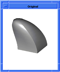
Figure. Take-off Vector Changes
Local Vertex Modification with Skinning and Lofting
Scheme Extensions: slinterface:modify-vertex, slinterface:build-edges
C++ APIs: api_modify_wire_sli, api_build_edges_sli
Local vertex modification allows the user to move selected vertices along the coedges they separate. Generally speaking, after the call to slinterface:breakup-wires, additional vertices and coedges will be generated on one or more of the skinning or lofting profiles. With a call to slinterface:modify-vertex, a vertex can be repositioned along its neighboring coedges. In the following figure, which shows the use of the skinning and lofting modify vertex command, the circled vertex can be moved along the wire profile in either direction.
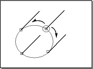
Figure. Local Vertex Modification
Scheme Example
| ; Build the necessary geometry for a sweep. (define frame1 (wcs (position 0 0 0) (gvector 1 0 0) (gvector 0 1 0))) (entity:set-color frame1 1) (define frame2 (wcs (position 0 0 0) (gvector 1 0 0) (gvector 0 0 1))) (wcs:set-active frame2) (entity:set-color frame2 1) (define wire_5 (wire-body (list (edge:circular (position 50 50 60) 20 0 360)))) (define wire_6 (wire-body (list (edge:circular (position 50 50 90) 20 0 360)))) (zoom-all) (wcs:set-active frame1) (define wire_1 (wire-body (list (edge:linear (position -20 30 0) (position 120 30 0)) (edge:linear (position 120 30 0) (position 120 20 0)) (edge:linear (position 120 20 0) (position -20 20 0)) (edge:linear (position -20 20 0) (position -20 30 0))))) (define dom1 (law "domain (vec (0, 0, 1), 0, 140)")) (define dom2 (law "domain (vec (0, 0, 1), 0, 10)")) (define dom3 (law "domain (vec (0, 0, 1), 0, 140)")) (define dom4 (law "domain (vec (0, 0, 1), 0, 10)")) (define laws1 (list dom1 dom2 dom3 dom4)) (define wire_2 (wire-body (list (edge:linear (position 10 30 30) (position 90 30 30)) (edge:linear (position 90 30 30) (position 90 20 30)) (edge:linear (position 90 20 30) (position 10 20 30)) (edge:linear (position 10 20 30) (position 10 30 30))))) (define dom1 (law "domain (vec (0, 0, 1), 0, 80)")) (define dom2 (law "domain (vec (0, 0, 1), 0, 10)")) (define dom3 (law "domain (vec (0, 0, 1), 0, 80)")) (define dom4 (law "domain (vec (0, 0, 1), 0, 10)")) (define laws2 (list dom1 dom2 dom3 dom4)) (zoom-all) (define wire_3 (wire-body (list (edge:linear (position 20 20 50) (position 80 20 50)) (edge:linear (position 80 20 50) (position 80 13 43)) (edge:linear (position 80 13 43) (position 20 13 43)) (edge:linear (position 20 13 43) (position 20 20 50))))) (define dom1 (law "domain (vec (0, -0.7, 0.7), 0, 40)")) (define dom2 (law "domain (vec (0, -0.7, 0.7), 0, 10)")) (define dom3 (law "domain (vec (0, -0.7, 0.7), 0, 40)")) (define dom4 (law "domain (vec (0, -0.7, 0.7), 0, 10)")) (define laws3 (list dom1 dom2 dom3 dom4)) (zoom-all) (define coedges1 (entity:coedges wire_1)) (define coedges2 (entity:coedges wire_2)) (define coedges3 (entity:coedges wire_3)) (define coedges5 (entity:coedges wire_5)) (define coedges6 (entity:coedges wire_6)) (define section1 (section coedges1 laws1 #f 100)) (define section2 (section coedges2 laws2 #f 50)) (define section3 (section coedges3)) (define section5 (section coedges5)) (define section6 (section coedges6)) ; Start the lofting step. (define sect (list section2 section3 section5 section6)) (define interface (slinterface:lofting sect)) (define tempWires (slinterface:wires interface)) (entity:set-color tempWires 1) ; Align, breakup and minimize the temporary lofting wires. (slinterface:align-wires interface) (slinterface:minimizetwist-wires interface) (slinterface:breakup-wires interface) ; Spend some time looking at the edges. (define previewEdges (slinterface:build-edges interface)) ; Delete the edges. (entity:delete previewEdges) ; Move some vertices around (slinterface:modify-vertex interface (list-ref tempWires 3) (position 30.2667875017707 -90 53.255813953488) (position 40.288231 -90 67.483751)) (slinterface:modify-vertex interface (list-ref tempWires 3) (position 69.7332124982292 -90 53.255813953488) (position 59.71176899999 -90 67.483751)) (slinterface:modify-vertex interface (list-ref tempWires 3) (position 69.7332124982292 -90 46.744186046511) (position 66.098883 -90 61.867012)) (slinterface:modify-vertex interface (list-ref tempWires 3) (position 30.2667875017708 -90 46.744186046511) (position 33.901117 -90 61.867012)) (slinterface:modify-vertex interface (list-ref tempWires 2) (position 30.2667875017707 -60 53.255813953488) (position 40.288231 -60 67.483751)) (slinterface:modify-vertex interface (list-ref tempWires 2) (position 69.7332124982292 -60 53.255813953488) (position 59.71176899999 -60 67.483751)) (slinterface:modify-vertex interface (list-ref tempWires 2) (position 69.7332124982292 -60 46.744186046511) (position 66.098883 -60 61.867012)) (slinterface:modify-vertex interface (list-ref tempWires 2) (position 30.2667875017708 -60 46.744186046511) (position 33.901117 -60 61.867012)) ; Spend some time looking at the edges. (define previewEdges (slinterface:build-edges interface)) ; Delete the edges. (entity:delete previewEdges) ; We like them now, so build the body. (define body (slinterface:build-body interface)) (slinterface:delete-interface interface) |
Example. Modify Vertex
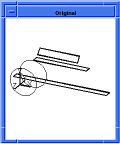
Figure. Modify Vertex
[Top]
© 1989-2007 Spatial Corp., a Dassault Systèmes company. All rights reserved.