Modifying Models
Once the general shape of a solid is established, it can be refined through other processes. These might include:
- Moving and/or rotating the model, or transforming it in some other way
- Uniting or intersecting it with another solid
- Subtracting it from another solid, or vice versa
- Adding blends to the model, such as fillets and chamfers
- Performing local operations on the model, such as offsetting
- Performing shelling on the model to create a hollow solid body
- Performing freeform deformations on the model
Transforming a Model
Many ACIS creation techniques for solid and surface primitives are very basic. They tend to create objects at the working coordinate system origin with simple geometric relationships. The reason for this is that it simplifies the syntax of the primitive operations if positioning and orientation are left to later steps. Because of this, model entities may need to be moved.
ACIS refers to this operation as a transformation. A transformation can be used for things such as scaling, reflection, inversion, rotation, in addition to repositioning.
Internally, ACIS transformations are essentially matrix operations performed on the modeling entity. When combining transformations and/or applying them to an entity, ACIS performs the more complex linear algebra and matrix tasks for you, allowing you to define in a more general sense the operation desired.
To move entities to more suitable locations, the Scheme extension entity:transform can be used with defined transformations.
The following example creates a simple block with one corner at the origin. A translation transformation is defined that moves the block along a vector. A rotation transformation is defined that rotates the block 45 degrees around a vector.
Scheme Example
| ; Create a solid block. (define my_block (solid:block (position 0 0 0) (position 10 15 20))) ;; my_block ; my_block => #[entity 2 1] ; Create a copy of the block. (define my_block2 (entity:copy my_block)) ;; my_block2 => #[entity 3 1] ; Create a transform to move the block. (define my_t_move (transform:translation (gvector 10 12.5 0))) ;; my_t_move (define my_t_rotate (transform:rotation (position 15 20 0) (gvector -1 0 1) 45)) ;; my_t_rotate (define my_transform (transform:compose my_t_move my_t_rotate)) ;; my_transform ; Apply the transform to the block. (entity:transform my_block my_transform) ;; #[entity 2 1] ; Refresh the view so that both entities are visible. (view:refresh) ;; #[view 293023412] ; Save the results to an output file. (part:save "tmptrans1.sat") ;; #t |
Some of the Scheme extensions related to transformations on models are:
- afig:apply-transform
- Apply a transform to an animation-figure.
- afig:get-transform
- Get the current transformation for an animation-figure.
- afig:set-transform
-
Set the transform for an animation-figure.
- curve:transform
- Modifies a curve or edge by applying a transform.
- entity:fix-transform
- Applies a body transformation to all underlying geometry.
- entity:transform
- Applies a transform to a single entity or list of entities.
- gvector:transform
- Applies a transform to a gvector.
- position:transform
- Applies a transform to a position.
- transform:axes
- Creates a transform that takes an object from model space to the space defined by the new origin and axes.
- transform:compose
- Concatenates two transforms.
- transform:copy
- Copies a transform.
- transform:identity
- Creates an identity transform.
- transform:inverse
- Creates an inverse transform.
- transform:reflection
- Creates a transform to mirror an object through an axis.
- transform:rotation
- Creates a transform to rotate an object about an axis.
- transform:scaling
- Creates a scaling transform.
- transform:translation
- Creates a translation transform.
- transform?
- Determines if a Scheme object is a transform.
- wcs:from-transform
- Creates a work coordinate system given a transform.
- wcs:to-model-transform
- Gets the transform of the active WCS to model space.
- wcs:to-wcs-transform
- Gets the transform from the active WCS to the specified WCS.
Using Booleans
Boolean operations illustrate the true power of ACIS and solid models. Booleans are used to unite or intersect two solid bodies, or to subtract one solid body from another.
The following example creates a block and a cylinder and uses Boolean operations to unite them. Instead of solid:unite, solid:intersect or solid:subtract could have been employed to create other unique solids.
Scheme Example
| ; Create a solid block. (define my_block (solid:block (position -20 -20 -20) (position 20 20 20))) ;; my_block ; Create a cylinder. (define my_cyl (solid:cylinder (position 20 0 -20) (position 20 0 20) 20))) ;; my_cyl ; Unite the two bodies into a new body. (define my_united (solid:unite my_block my_cyl)) ;; my_united ; Save the results to an output file. (part:save "tmpbool1.sat") ;; #t |
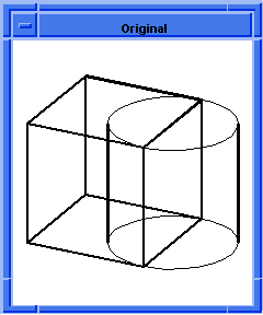

Figure. Unite Block and Cylinder
Some of the Scheme extensions related to Boolean operations on models are:
- body:combine
-
Combines a list of solid and/or wire bodies into a single body.
- body:separate
- Separates a single disjoint body into multiple entities.
- bool:intersect
- Intersects two or more bodies.
- bool:merge
- Combines faces and edges of equivalent geometry.
- bool:merge-faces
- Combines specific faces on a body.
- bool:nonreg-intersect
- Intersects two or more non-regularized bodies.
- bool:nonreg-subtract
- Subtracts one or more non-regularized bodies from a body.
- bool:nonreg-unite
- Unites two or more non-regularized bodies.
- bool:regularise
- Regularizes an entity.
- bool:subtract
- Subtracts one or more bodies from a body.
- bool:unite
- Unites two or more bodies.
- curve:intersect
- Gets the intersection between two edges or curves.
- edge:project-to-plane
- Projects an edge onto a plane.
- edge:split
- Splits an edge into two entities at a specified position.
- edge:trim-intersect
- Trims both edges to the intersection of the edges.
- face:intersect
- Gets the intersection curve between two faces.
- position:project-to-line
- Gets the projection of a position on to a line.
- position:project-to-plane
- Gets the projection of a position onto a plane.
- solid:imprint
- Imprints curves of intersection of two bodies onto the faces of bodies.
- solid:imprint-stitch
- Joins body1 and body2 along the intersection graph.
- solid:intersect
- Intersects a list of solids.
- solid:planar-slice
- Slices a solid body with a plane to produce a wire body.
- solid:slice
- Gets the intersection graph between two bodies and returns it as a wire body.
- solid:split
- Splits all periodic faces of a body along the seams.
- solid:stitch
- Joins body1 and body2 along edges or vertices of identical geometry.
- solid:subtract
- Subtracts a list of solids from a solid.
- solid:unite
- Unites two solids.
Blending a Solid
Blending is used frequently in mechanical engineering designs. It permits:
- Chamfering or rounding sharp edges
- Adding a chamfer or fillet between two faces (for example, adding material)
- Variable blending and chamfering (blend radius or chamfer size are not constant)
The following example picks up where Sweeping example left off. In the sweeping example, a wire body consisting of linear edges was created. This is offset, creating another wire body that has rounded corners. This wire body is then swept into a solid. The blending example takes some of the edges of that solid and applies a constant radius blend to them, as is shown in the following figure.
After creating the swept solid, defines the blend radius and assigns this to a list of edges. The list of edges, my_list, is simply the list of edges obtained from the wire offset operation and then later used as the profile in sweeping. Either a single edge or a group of edges can have the blend attribute assigned to it. Once the edges have a blend attribute, the network of blend edges is passed into the blend:network Scheme extension, which completes the blend.
Note: The blend:get-network Scheme extension is used to get all edges associated with a blend attribute from just one edge of the list.
Scheme Example
| ;--------- Copy of the Offsetting a Wire Body Example ;--------- (below this line)v ; Define the positions to be used. (define my_point1 (position 0 0 0)) ;; my_point1 (define my_point2 (position 20 0 0)) ;; my_point2 (define my_point3 (position 20 10 0)) ;; my_point3 (define my_point4 (position 0 10 0)) ;; my_point4 ; Create edge 1 as a sine edge. (define my_linear1 (edge:linear my_point1 my_point2)) ;; my_linear1 ; Create edge 2 as a linear edge. (define my_linear2 (edge:linear my_point2 my_point3)) ;; my_linear2 ; Create edge 3 as a spline curve. (define my_linear3 (edge:linear my_point3 my_point4)) ;; my_linear3 ; Create edge 4 as a spline curve. (define my_linear4 (edge:linear my_point4 my_point1)) ;; my_linear4 ; Create a wire-body from a list of edges. (define my_wirebody (wire-body (list my_linear1 my_linear2 my_linear3 my_linear4))) ;; my_wirebody (define my_offset (wire-body:offset my_wirebody 5 "r")) ;; my_offset (entity:delete my_wirebody) ;; () (define my_profile my_offset) ;; my_profile ; Create a list of edges for use later. (define my_list (entity:edges my_profile)) ;; my_list ; Create a vector path for sweeping. (define my_vec_path (gvector 0 0 20)) ;; my_vec_path ; Sweep the profile along this vector. Create it as a solid. (define my_sweep (sweep:along-vector my_profile #t my_vec_path)) ;; my_sweep ;--------- Copy of the Offsetting a Wire Body Example ;--------- (above this line) ; Modify the model by blending all of the edges along ; the base. (blend:const-rad-on-edge my_list 3) ;; (#[entity 19 1] #[entity 23 1]) (blend:network (blend:get-network (car my_list))) ;; #[entity 19 1] ; Save the results to an output file. (part:save "tmpblend1.sat") ;; #t |
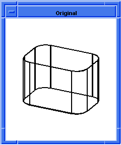


Figure. Blending Edges
Some of the Scheme extensions related to blending solids are:
- blend:chamfer-on-edge
-
Attaches a chamfer blend attribute to each edge in the input list.
- blend:complete
- Executes the third phase of blending.
- blend:const-rad-on-edge
- Attaches a constant radius blend attribute to each edge in the input list.
- blend:edge-info
- Lists the edge blend type and internal data values.
- blend:get-network
- Gets a list of all edges and vertices that are in the same blend network as the given entity.
- blend:get-smooth-edges
- Gets a list of all edges that smoothly connect to a given edge.
- blend:local
-
Creates a blend in a non-manifold body by adding faces locally around a given
edge, blending the edge, and removing the added faces.
- blend:make-sheet
- Executes the first phase of blending which creates a blend sheet.
- blend:make-wire
- Executes the second phase of blending which creates a wire intersection.
- blend:network
- Creates blends on a list of edges and vertices that make up a single blend network.
- blend:on-vertex
- Attaches vertex blend attributes to each vertex in the input list.
- blend:remove-from-edge
- Removes blend attributes, if any, from the input edge.
- blend:remove-from-vertex
- Removes blend attributes, if any, from the input vertex.
- blend:var-rad-on-edge
- Attaches a variable radius blend attribute to each edge in the input list.
- blend:vertex-info
- Lists the vertex blend type and internal data values.
- edge:fillet
- Creates a fillet blend on two edge entrays (entities with rays).
- solid:blend-edges
- Creates a cylindrical blend on a list of edges.
- solid:chamfer-edges
- Creates a chamfer blend on a list of edges.
Local Operations, Shelling, and Deformable Surfaces
The Local Operations Component, Shelling Component, and ACIS Deformable Modeling Component all provide specialized functionality for modifying models.
Local Operations
The following example shows the taper faces local operation.
Scheme Example
| (define my_block2 (solid:block (position -25 -25 -10) (position 25 25 10))) ;; my_block2 ; my_block2 => #[entity 2 1] (solid:blend-edges (pick:edge (ray (position 0 0 0) (gvector 1 -1 0))) 20) ;; (#[entity 2 1]) (lop:taper-faces (list (pick:face (ray (position 0 0 0) (gvector 1 0 0))) (pick:face (ray (position 0 0 0) (gvector 0 -1 0))) (pick:face (ray (position 0 0 0) (gvector 1 -1 0)))) (position 0 0 -10) (gvector 0 0 1) 45) ;; #[entity 2 1] ; Save the results to an output file. (part:save "tmplocop1.sat") ;; #t |
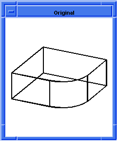

Figure. Taper Faces Local Operation
Shelling
The following example shows how a shelling operation works by creating a hollow solid body.
Scheme Example
| ; shell:hollow-body ; Create a solid block. (define my_block (solid:block (position -20 -20 -20) (position 20 20 20))) ;; my_block => #[entity 1 1] (define my_face (car (entity:faces my_block))) ;; my_face => #[entity 2 1] ; Hollow the body (shell:hollow-body my_face 10) (gvector 0 0 1))) 10) ;; #[entity 1 1] ; Save the results to an output file. (part:save "tmpshell1.sat") ;; #t |
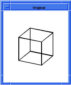

Figure. Hollow Body
Deformable Modeling
The following example shows how to perform freeform deformations on a simple face.
Scheme Example
| ; Make a test face (define my_dsmodel ( ds:test-face 6 6 36 36 0)) ;; my_dsmodel ; Show the load and constraints ( ds:set-draw-state my_dsmodel 1 (+ 4 8)) ;; () ; Make a spring and add it to the test-face (define my_spring (ds:add-spring my_dsmodel 1 (par-pos 0.5 0.5) (position 10 10 15) 100)) ;; my_spring ; Solve to see deformation effect (ds:solve my_dsmodel) ;; () ; Compress the spring and display (ds:set-load-gain my_dsmodel my_spring 1000 #t) ;; 4 (ds:solve my_dsmodel) ;; () ; The surface should just barely be deformed ; increasing the spring gain reduces the distance ; between the spring end points. ; Compress the spring and display (ds:set-load-gain my_dsmodel my_spring 10000 #t) ;; 4 (ds:solve my_dsmodel) ;; () ; Compress the spring and display (ds:set-load-gain my_dsmodel my_spring 100000 #t) ;; 4 (ds:solve my_dsmodel) ;; () ; The spring displaces the surface by larger ; ang larger amounts. ; Commit the changes back to the model so it can be saved. (ds:commit my_dsmodel) ;; () ; Save the results to an output file. (part:save "tmpdmod1.sat") ;; #t ; When loading this part, the deformed surface can be ; seen by rendering it or turning on silhouette lines. |

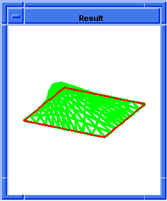
Figure. Free-Form Deformations on a Face
[Top]
© 1989-2007 Spatial Corp., a Dassault Systèmes company. All rights reserved.