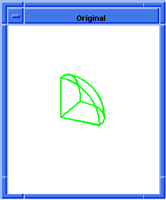
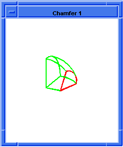
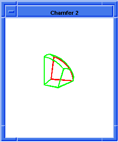
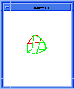
Scheme Extensions
|
|
|
|
Technical Article
|
| Scheme is a public domain programming language, based on the LISP language,
that uses an interpreter to run commands. ACIS provides extensions (written in
C++) to the native Scheme language that can be used by an application to
interact with ACIS through its Scheme Interpreter. The C++ source files for
ACIS Scheme extensions are provided with the product. Spatials Scheme based
demonstration application, Scheme ACIS Interface Driver Extension (Scheme
AIDE), also uses these Scheme extensions and the Scheme Interpreter.
|
blend:chamfer
- Action
-
Attaches a chamfer blend attribute to a sequence of edges.
-
Filename
-
scm/scmext/blnd/nblndscm.cpp
-
APIs
-
api_blend_graph,
api_fix_blends,
api_set_const_chamfers,
api_smooth_edge_seq
-
Syntax
-
(blend:chamfer edge left-range [right-range=left-range
-
[start-setback=0 end-setback=start-setback
-
[start-setback-diff=0 end-setback-diff=start-setback-diff]
-
[start-stop-angle=0 end-stop-angle=start-stop-angle]]]]]
-
["FIX" | "SINGLE"] [acis-opts])
-
Arg Types
-
-
Returns
-
boolean
| entity
Description
The default action is to place attributes on the smoothly connected edges of
the given edge. The last argument, if given as
fix
completes the blend for the sequence. If given as
single, the attribute is placed only on
the picked edge (not the sequence).
- Arguments
-
entity-list
is a list of input entities to which chamfer blend will be attached.
-
left-range
is a distance between the original edge and spring curve edge on the left side
of the edge. Left side is defined with reference to direction of edge.
-
right-range
is a distance between the original edge and spring curve edge on the right side
of the edge. Right side is defined with reference to direction of edge.
-
start-setback
and
end-setback
represent a distance from the vertex to the start of the blended edge.
-
start-setback-diff
and
end-setback-diff
allow the creation of non-circular cross curves. The double represents right
setback - left setback. Refer to
api_set_const_rounds for more details.
-
start-stop-angle
and
end-stop-angle
represent the angle of the capping face used if the setbacks cause the blend to
stop before the end of the edge.
-
fix
completes the blend for the sequence.
-
single
places the attribute only on the picked edge.
-
acis-opts
contains journaling and versioning information.
; blend:chamfer
; Create a solid block.
(define block1
(solid:block (position -20 -20 -20)
(position 20 20 20)))
;; block1
; Get a list of the solid blocks edges.
(define list1 (entity:edges block1))
;; list1
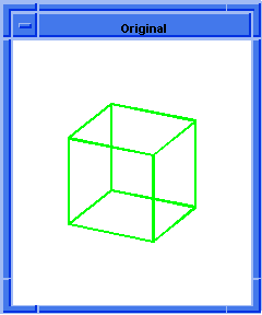
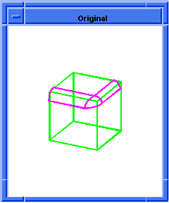
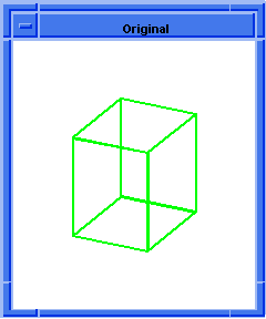
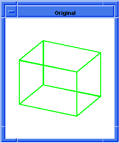
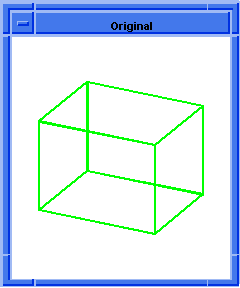
; OUTPUT Original
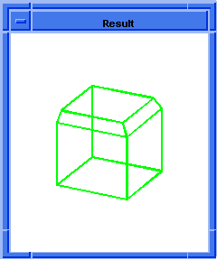
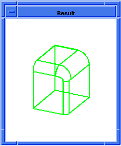
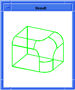
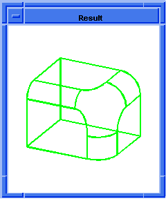
(blend:chamfer (car list1) 5 8 "fix")
;; #t
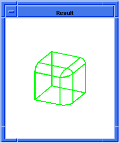
; OUTPUT Result
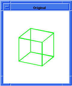  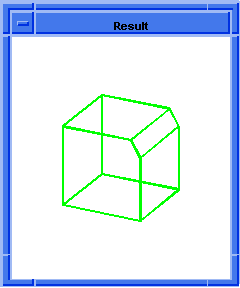
Figure. blend:chamfer
|
[Top]
blend:chamfer-on-edge
- Action
-
Attaches a chamfer blend attribute to each edge in the input list.
-
Filename
-
scm/scmext/blnd/blnd_scm.cpp
-
APIs
-
api_del_entity,
api_set_const_chamfers
-
Syntax
-
(blend:chamfer-on-edge entity-list left_range [right-range=left_range
-
start-setback=0 end-setback=start-setback
-
[start-setback-diff=0 end-setback-diff=start-setback-diff]
-
[start-stop-angle=0 end-stop-angle=start-stop-angle]]]]
-
[acis-opts])
-
Arg Types
-
-
Returns
-
(entity
...)
Description
This extension attaches a chamfer blend attribute to each edge in the input
entity-list. The actual blending is not performed until blend:network
is called.
offset-left
and
offset-right
represent the planar chamfer boundaries offset from the edge. The sense of the
edge determines the left side and the right side. If only one offset value is
provided, it applies to both
offset-left
and
offset-right.
The optional
setback-start
and
setback-end
represent a distance from the vertex to the start of the blended edge. If only
one setback value is provided, it is applied to both
setback-start
and
setback-end.
This extension returns the input entity list.
- Arguments
-
entity-list
is a list of input entities to which chamfer blend will be attached.
-
left-range
is a distance between the original edge and spring curve edge on the left side
of the edge. Left side is defined with reference to direction of edge.
-
right-range
is a distance between the original edge and spring curve edge on the right side
of the edge. Right side is defined with reference to direction of edge.
-
start-setback
and
end-setback
represent a distance from the vertex to the start of the blended edge.
-
start-setback-diff
and
end-setback-diff
allow the creation of non-circular cross curves. The double represents right
setback - left setback. Refer to
api_set_const_rounds for more details.
-
start-stop-angle
and
end-stop-angle
represent the angle of the capping face used if the setbacks cause the blend to
stop before the end of the edge.
-
acis-opts
contains journaling and versioning information.
[Top]
blend:complete
- Action
-
Attaches a sheet to a blank body using wire. This is the third phase of
blending.
-
Filename
-
scm/scmext/blnd/blndtest.cpp
-
APIs
-
api_complete_blends
-
Syntax
-
(blend:complete wire sheet body [acis-opts])
-
Arg Types
-
-
Returns
-
body
Description
This, the 3rd phase of blending, calls the boolean phase two to attach the
sheet to the blank body, body, using wire.
The first phase of blending creates a blend sheet, which is the input argument
sheet. The second phase of blending
calls the boolean phase one to create an intersection boolean, which is the
input argument
wire.
Note: blend:round combines blend:ss-sheet,
blend:wire, and blend:complete.
- Arguments
-
sheet
is a input blend sheet which is attached to the bland body.
-
wire
is used to attach sheet to the blank body.
-
body
is a blank body to which blend sheet is attached.
-
acis-opts
are optional parameters that are specific to the component and general ACIS
options such as the journal and version information.
; blend:complete
; First stage of blending - create a solid block.
(define block1
(solid:block (position -20 -20 -20)
(position 5 15 20)))
;; block1
; Get a list of the solid blocks edges.
(define edges (entity:edges block1))
;; edges
(define list1
(list (car edges)
(car (cdr (cdr (cdr edges))))))
;; list1
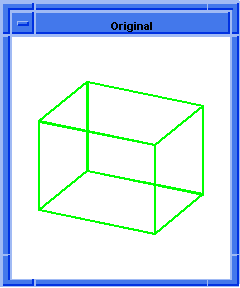
; OUTPUT Original
; Attach constant radius blend to 2 connected edges.
(define blend (blend:const-rad-on-edge list1 5))
;; blend
;First stage of Blending.
(define sheet1 (blend:make-sheet list1))
;; sheet1
; Second stage of Blending - create wire
; intersection.
(define wire1 (blend:make-wire sheet1 block1))
;; wire1
; Third stage of Blending - attach sheet to blank
; body.
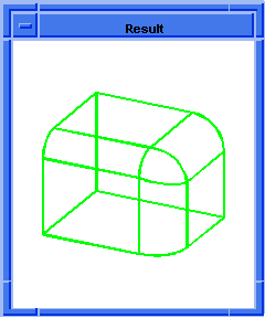
(define blend-c (blend:complete wire1 sheet1 block1))
;; blend-c
(view:refresh)
;; #[view 1079201720]
; OUTPUT Result
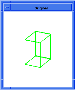  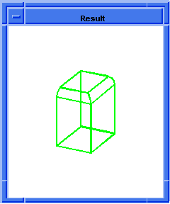
Figure. blend:complete
|
[Top]
blend:const-rad-on-edge
- Action
-
Attaches a constant radius blend attribute to each edge in the input list.
-
Filename
-
scm/scmext/blnd/blnd_scm.cpp
-
APIs
-
api_del_entity,
api_set_const_rounds
-
Syntax
-
(blend:const-rad-on-edge entity-list blend-radius
-
[start-setback=0 end-setback=start-setback
-
[start-setback-diff=0 end-setback-diff=start-setback-diff]
-
[start-stop-angle=0 end-stop-angle=start-stop-angle]]]
-
[blend-how=0] [acis-opts])
-
Arg Types
-
-
Returns
-
(entity
...)
Description
This extension attaches a constant radius blend attribute to each edge in the
input
entity-list. The actual blending is not
performed until blend:network is called. The
optional
setback-start
and
setback-end
represent a distance from the vertex to the start of the blended edge. If only
one setback value is provided, it is applied to both the
setback-start
and
setback-end. The angle of the stop
controlled by the setback can also be optionally specified. This extension
returns the input entity list.
- Arguments
-
entity-list
is a list of input entities.
-
blend-radius
is a constant radius blend attribute.
-
start-setback
and
end-setback
represent a distance from the vertex to the start of the blended edge.
-
start-setback-diff
and
end-setback-diff
allow the creation of non-circular cross curves. The double represents right
setback - left setback. Refer to
api_set_const_rounds for more details.
-
start-stop-angle
and
end-stop-angle
represent the angle of the capping face used if the setbacks cause the blend to
stop before the end of the edge.
-
blend-how
controls capping versus rollon behavior when the blend encounters another edge
or face.
Values include:
0 = bl_how_default
1 = bl_how_cap
2 = bl_how_roll_on
-
acis-opts
contains journaling and versioning information.
; blend:const-rad-on-edge
; Create a solid block.
(define block1
(solid:block (position -20 -20 -20)
(position 20 20 20)))
;; block1
; Get a list of the solid blocks edges.
(define list1 (entity:edges block1))
;; list1
(define short-list
(list (car list1)
(car (cdr (cdr (cdr list1))))))
;; short-list
; OUTPUT Original
; Set a constant radius blend.
(define blend (blend:const-rad-on-edge short-list 5))
;; blend
; Blend the network.
(blend:fix (car short-list))
;; #t
(view:refresh)
;; #[view 1079201720]
; OUTPUT Result
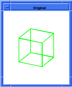  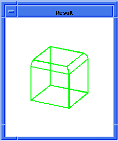
Figure. blend:const-rad-on-edge
|
[Top]
blend:delete
- Action
-
Deletes a network of existing blend attributes on a given body.
-
Filename
-
scm/scmext/blnd/nblndscm.cpp
-
APIs
-
api_blend_graph,
api_delete_blends
-
Syntax
-
(blend:delete entity [single] [acis-opts])
-
Arg Types
-
-
Returns
-
string
Description
Deletes a network of existing blend attributes on a given body. If the keyword
single is supplied, only the blend attributes on the picked entity are deleted.
- Arguments
-
entity
is an input entity whose existing blend attributes will be deleted.
-
single
is to delete only the blend attribute on the picked entity.
-
acis-opts
contains journaling and versioning information.
blend:delete
; reate solid block.
(define block1
(solid:block (position -20 -20 -20)
(position 5 15 20)))
;; block1
; Get a list of the solid blocks edges.
(define list1 (entity:edges block1))
;; list1
; Define two specific edges in a list.
(define short-list
(list (car list1)
(car (cdr (cdr (cdr list1))))))
;; short-list
; Attach a constant radius blend to two edges.
(define blend (blend:const-rad-on-edge short-list 5))
;; blend
; (#[entity 3 1] #[entity 6 1])
; OUTPUT Original
; Delete the blend network you just created.
(blend:delete (entity 3 1) (entity 6 1))
;; 1
; Refresh the picture so you can see the result.
(view:refresh)
;; #[view 13042062]
; OUTPUT Result
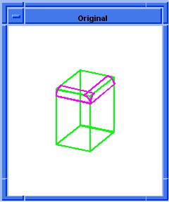  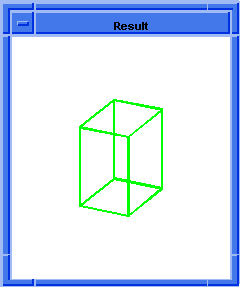
Figure. blend:delete
|
[Top]
blend:edge-info
-
Action
-
Gets a list of the edge blend type and internal data values.
-
Filename
-
scm/scmext/blnd/blnd_scm.cpp
-
APIs
-
None
-
Syntax
-
(blend:edge-info edge)
-
Arg Types
-
-
Returns
-
((pair
... ) |
boolean)
Description
This extension tests the edges for blend attributes. It returns a list
containing the blend type and internal data values. If no blend attributes
exist, this extension returns #f. This command is called before the command
blend:network, because blend:network deletes the edge
entities to which the blend attributes are attached.
- Arguments
-
edge
is an input edge which is tested for blend attributes.
; blend:edge-info
; Create a solid block.
(define block1
(solid:block (position -20 -20 -20)
(position 20 20 20)))
;; block1
; Get a list of the solid blocks edges.
(define list1 (entity:edges block1))
;; list1
; Set a constant radius blend.
(define blend (blend:round (car list1) 5))
;; blend
; (#[entity 3 1])
; List the edge blend type and value.
(blend:edge-info (car list1))
;; (const radius (radius . 5)
;; (setback at start . 0)
;; (setback at end . 0))
|
[Top]
blend:enquire
- Action
-
Returns blend attribute details for a given network.
-
Filename
-
scm/scmext/blnd/nblndscm.cpp
-
APIs
-
api_smooth_edge_seq
-
Syntax
-
(blend:enquire edge)
-
Arg Types
-
-
Returns
-
edge
| (edge
...)
Description
Returns blend attributes for a given network. If edge is part of a sequence,
the sequence details are printed out.
- Arguments
-
edge
is an input edge.
; blend:enquire
; Create solid block.
(define block1
(solid:block (position -20 -20 -20)
(position 20 20 20)))
;; block1
; Get a list of the solid blocks edges.
(define list1 (entity:edges block1))
;; list1
; Set a constant radius blend.
(define blendround (blend:round (car list1) 5))
;; blendround
; (#[entity 3 1])
; Request details of edge
(blend:enquire (car list1))
; edge has face-face round
; radius 5
;; ()
|
[Top]
blend:entities
- Action
-
Performs general blending commands.
-
Filename
-
scm/scmext/blnd/blndopts_scm.cpp
-
APIs
-
api_fix_blends,
api_get_edges,
api_get_faces,
api_set_const_chamfers,
api_set_var_blends,
api_set_vblend,
api_set_vblend_auto,
api_set_vblend_autoblend,
api_smooth_edge_seq,
api_smooth_edges_to_curve
-
Syntax
-
(blend:entities [entity-list] [option [data]]...)
-
Arg Types
-
-
Returns
-
entity
| entity
...
-
Arguments
-
entity-list
argument defines the entities to be blended.
-
option
argument can be defined as any of the following:
- "chamfer"
-
Attaches a chamfer blend attribute to a sequence of edges. A
chamfer requires two values defined in the data argument.
- "setback"
-
Specifies the distance along an edge, back from the vertex, at
which the blend stops. Setback requires a setback value defined in the data
argument.
- "fix"
-
Repairs a blend network.
- "autosetback"
-
Calculates a best-fit setback for each end of the blended edge.
Autosetback is applied to a vertex blend using the
api_set_vblend_auto function.
- "autoblend"
-
Overrides autosetbacks with rolling ball vertex blends to produce
an n-sided path vertex blend in preference to a rolling ball blend.
- "round"
-
This argument specifies that the edge is given a rounded blend of
the specified radius. A radius must be defined in the data argument as a
positive value and specifies the radius dimension in global body space.
- "single"
-
Specifies that fix should be applied only to the single edge or
vertex picked, instead of to the whole set of edges and/or vertices forming the
blendable network attached to that edge or vertex.
- "bulge"
-
Defines the fullness of the vertex blend. Requires a value defined
in the data argument.
- "show"
-
Highlights the entities that have blend attributes.
-
data
provides the additional information required for some of the option arguments,
for example, radius for round, two distance values for chamfer, a value for
setback and bulge.
[Top]
blend:fix
- Action
-
Repairs a blend network.
-
Filename
-
scm/scmext/blnd/nblndscm.cpp
-
APIs
-
api_blend_graph,
api_fix_blends
-
Syntax
-
(blend:fix edge [acis-opts])
-
Arg Types
-
-
Returns
-
unspecified
Description
Fixes a blend network on a body. Place the attributes on the edges/vertices
before initiating this command.
- Arguments
-
edge
is an input edge for fixing blend network on a body.
-
acis-opts
contains journaling and versioning information.
; blend:fix
; Fix a blend network on a body.
; create a solid block.
(define block (solid:block (position -25 -10 -30)
(position 40 20 30)))
;; block
; Preview the selected blend prior to blending
(define preview (blend:round
(list-ref (entity:edges block) 3) 5))
;; preview
; OUTPUT Original
; Apply the blend fix.
(blend:fix (list-ref (entity:edges block) 3))
;; #t
; OUTPUT Result
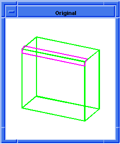  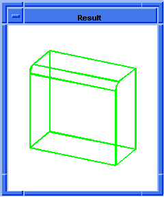
Figure. blend:fix
|
[Top]
blend:get-network
- Action
-
Gets a list of all edges and vertices that are in the same blend network as the
given entity.
-
Filename
-
scm/scmext/blnd/blnd_scm.cpp
-
APIs
-
api_blend_graph
-
Syntax
-
(blend:get-network entity [acis-opts])
-
Arg Types
-
-
Returns
-
(entity
...) | (vertex
...)
Description
This extension returns a list of all edges and/or vertices that make up the
blend network. It tests the specified entity for the types vertex or edge. It
then looks for all other networked vertices and edges. This command is called
before the command blend:network, because
blend:network deletes the edge entities to which the blend attributes are
attached.
- To be part of a blend network, an edge or vertex must be owned by a solid body,
have an attached blend attribute, and have one of the following be true.
-
-Meets an edge smoothly (tangent continuity) at either a blended or unblended
vertex.
-
-Meets an edge or several edges at a blended vertex.
-
-Meets no more than one other blended
EDGE at an unblended vertex, which is called a blend pair.
The returned list contains this network, including the given entity. The list is
empty when the given entity has no blend attribute.
- Arguments
-
entity
is the specified entity for the types vertex and edge, for testing.
-
acis-opts
contains journaling and versioning information.
; blend:get-network
; Create a solid block.
(define block1
(solid:block (position -20 -20 -20)
(position 20 20 20)))
;; block1
; Get a list of the solid blocks edges.
(define list1 (entity:edges block1))
;; list1
(define short-list
(list (car list1)
(car (cdr (cdr (cdr list1))))))
;; short-list
; short-list => (#[entity 3 1] #[entity 6 1])
; Attach a constant radius blend to two edges.
(define blendedge (blend:const-rad-on-edge
short-list 5))
;; blendedge
; (#[entity 3 1] #[entity 6 1])
; Get a list of all the edges and vertices that
; are in the blend network for one of the solid
; blocks edges.
(define blendlist (blend:get-network (car list1)))
;; blendlist
; (#[entity 3 1] #[entity 6 1])
; Blend the network.
(define network (blend:network (car short-list)))
;; network
; #[entity 2 1]
|
[Top]
blend:get-smooth-edges
- Action
-
Gets a list of all edges that smoothly connect to a given edge.
-
Filename
-
scm/scmext/blnd/blnd_scm.cpp
-
APIs
-
api_smooth_edge_seq
-
Syntax
-
(blend:get-smooth-edges entity [acis-opts])
-
Arg Types
-
-
Returns
-
(edge
...)
Description
This extension returns a list of edges that all join smoothly. Smoothly means
that they have tangent continuity at the common vertices. The given entity must
be of the type edge and be part of a solid body. If it does not join other
edges smoothly, it returns a list containing only one argument.
- Arguments
-
entity
is an input edge and a part of solid body.
-
acis-opts
contains versioning and journaling parameters. Must be the last argument, if
stated.
; blend:get-smooth-edges
; Create a wire body from a list of edges.
(define wire1
(wire-body (list (edge:linear (position 0 0 0)
(position 20 0 0))
(edge:circular (position 20 10 0) 10 -90 90)
(edge:linear (position 20 20 0)
(position 0 20 0))
(edge:linear (position 0 20 0)
(position 0 0 0)))))
;; wire1
; Sweep a wire along the wire body.
(define solid1 (solid:sweep-wire wire1 20))
;; solid1
; Get a list of the edges.
(define list1 (entity:edges solid1))
;; list1 Set the highlighting to get the smooth edges.
(define edges1
(car (cdr (cdr (cdr (cdr (cdr (cdr (cdr (cdr
(cdr (cdr list1))))))))))))
;; edges1
(define highlight (entity:set-highlight
(blend:get-smooth-edges edges1) #t))
;; highlight
; (#[entity 17 1] #[entity 14 1] #[entity 11 1])
; These edges all join together smoothly.
(define edges2 (car list1))
;; edges2
; Set the highlighting to get the smooth edges.
(define highlight2 (entity:set-highlight
(blend:get-smooth-edges edges2) #t))
;; highlight2
; (#[entity 7 1]) |
[Top]
blend:make-cross-curve
- Action
-
Creates a rib curve, running from one base entity to the other, at a location
along a blend determined by the v-parameter.
-
Filename
-
scm/scmext/blnd/blnd_scm.cpp
-
APIs
-
api_make_blend_cross_curve
-
Syntax
-
(blend:make-cross-curve edge real [acis-opts])
-
Arg Types
-
-
Returns
-
entity
Description
Gets an edge with an attached blend attribute and the value of a v-parameter
along the blend. Given an edge with an attached blend attribute (currently,
only
ATTRIB_VAR_BLEND or
ATTRIB_CONST_ROUND) and a v-parameter along the blend, this
extension creates a rib curve, running from one base entity to the other, at a
location along the blend determined by the v-parameter. (The v-parameter runs
along the blend, and the u-parameter runs from one base surface to the other.)
The v-parameter of the blend is the same as that of its defining curve, which
is generally the curve of the edge being blended.
Sometimes the blend cannot evaluate a cross curve at the given parameter, for
example, if the blend radius is too big. The returned entity is a rib curve.
- Arguments
-
edge
is an edge with an attached blend attribute and the value of a v-parameter
along the blend.
-
real
is the v-parameter - value of the parameter along the blend.
-
acis-opts
contains optional parameters that are specific to the component and general
ACIS options such as the journal and version information. The option argument
(must be the last argument) is a class derived from acis-options. -
Limitations
-
Currently, only
ATTRIB_VAR_BLEND or
ATTRIB_CONST_ROUND
; blend:make-cross-curve
; Set up views.
(part:clear)
;; #t
(define view (cond ((>= 0 (length (part:views)))
(define dlv (view:dl 0 0 600 600)))))
;; view
(define iso (map iso (env:views)))
;; iso
; Define geometry to illustrate command.
; Define cylinder length H, radius r, wing span
; S, and surface curvature R.
(define H 30.0)
;; H
(define r 4.0)
;; r
(define S 40.0)
;; S
(define R 8.0)
;; R
; Create a cylinder and then a wing.
(define cyl (solid:cylinder (position (/ H -2) 0 0)
(position (/ H 2) 0 0) r))
;; cyl
(define wing (solid:cylinder (position 0 0 0)
(position 0 (- 0 S) 0) R))
;; wing
; Create a tool to cut the wing.
(define tool (solid:block (position (/ S -2) (* -2 S)
(/ S -2)) (position (/ S 2) (* 2 S) (/ S 2))))
;; tool
; Slightly rotate and change the angle of the tool.
(define transform1 (entity:transform tool
(transform:rotation (position 0 0 0)
(gvector 1 0 0) -4)))
;; transform1
; Transform the tool.
(define transform2 (entity:transform tool
(transform:translation
(gvector 0 0 (+ (/ S -2) r)))))
;; transform2
(define subtract (solid:subtract wing tool))
;; subtract
; Round out the wings leading edge.
(option:set raysize (/ R 4))
;; 1
(define lead_edge (pick:edge (ray (position (/ R -2)
(/ S -2) R) (gvector 0 0 -1))))
;; lead_edge
; Attach the variable round blend attributes to edge.
; Blending preview visible in OpenGL only.
(define blend1 (blend:var-round lead_edge 1.0 0.25))
;; blend1
; Fix the blend network.
(define blend_fix (blend:fix lead_edge))
;; blend_fix
; Move wing into proper place.
(define move_wing (entity:transform wing
(transform:translation
(gvector 0 0 (- (* 0.75 r) R)))))
;; move_wing
; Unite the cylinder and the wing.
(define unite (solid:unite cyl wing))
;; unite
; Apply the transforms to the underlying geometry.
(define fix (entity:fix-transform cyl))
;; fix
; Apply the blend CONST_RADIUS attribute to all edges
; of the wing-cylinder intersection.
(option:set raysize (/ r 2))
;; 2
; Select the edge(s) to be blended.
(define round_edge (pick:edge (ray (position 0 0 0)
(gvector 0 -1 1))))
;; round_edge
; Find all the edges that join smoothly.
(define smooth-edges
(blend:get-smooth-edges round_edge))
;; smooth-edges
; Attach a constant radius blend attribute to each
; edge in the list.
(define blend2
(blend:const-rad-on-edge smooth-edges 4.5))
;; blend2
; Now, pick the front rounded edge.
(define currEdge (list-ref smooth-edges 1))
;; currEdge
; OUTPUT Original
; Create a cross curve.
(define cross-curve
(blend:make-cross-curve currEdge 1.0))
;; cross-curve
; Create an edge from the curve.
(define new_edge (edge:from-curve cross-curve))
;; new_edge
; Render the image.
(render)
;; ()
; OUTPUT Rendered
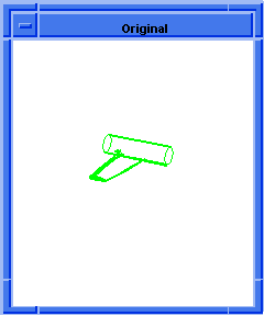  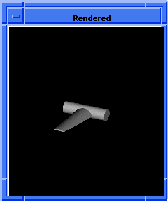
Figure. blend:make-cross-curve
|
[Top]
blend:make-sheet
- Action
-
Executes the first phase of blending which creates a blend sheet.
-
Filename
-
scm/scmext/blnd/blndtest.cpp
-
APIs
-
api_make_blend_sheet
-
Syntax
-
(blend:make-sheet entity-list [acis-opts])
-
Arg Types
-
-
Returns
-
body
Description
The first phase of blending creates a blend sheet for a given list of edges,
entity-list. Each edge has an implicit
blend attribute.
The created blend sheet contains one or more faces for each blended entity. The
blend body is the body that owns the blended entities. Attributes link the
sheet to the blend body, thereby facilitating the next stage of blending. (In
the next stage of blending, the sheet is combined with the blend body).
The sheet faces lie on new blend surfaces or on surfaces of the blend body where
these are needed to cap blends at ends of blended edges.
Where two blend faces are made for blended edges meeting non-smoothly in an
unblended vertex, the faces are trimmed to one another (i.e., are mitered) and
the sheet faces are joined.
- Arguments
-
entity-list
is a list of input entities to which blend sheet will be created.
-
acis-opts
contains optional parameters that are specific to the component and general
ACIS options such as the journal and version information. The option argument
(must be the last argument) is a class derived from acis-options.
; blend:make-sheet
; First stage of blending.
; Create a solid block.
(define block1
(solid:block (position -20 -20 -20)
(position 5 15 20)))
;; block1
; Get a list of the solid blocks edges.
(define edges1 (entity:edges block1))
;; edges1
; Attach constant radius blend to 2 connected edges.
(define list1
(list (car edges1)
(car (cdr (cdr (cdr edges1))))))
;; list1
; OUTPUT Original
; Attach constant radius blend to 2 connected edges.
(define attach (blend:const-rad-on-edge list1 5))
;; attach
; (#[entity 3 1] #[entity 6 1])
(define sheet1
(blend:make-sheet
(blend:get-network (car list1))))
;; sheet1
; OUTPUT Result
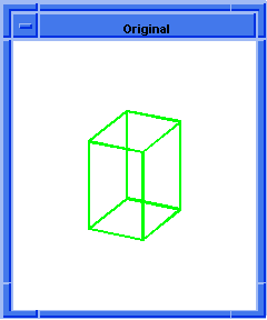  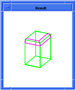
Figure. blend:make-sheet
|
[Top]
blend:make-ss-sheet
- Action
-
Executes the first phase of blending which creates a blend sheet.
-
Filename
-
scm/scmext/blnd/blndtest.cpp
-
APIs
-
api_concl_blend_ss,
api_do_one_blend_ss,
api_init_blend_ss
-
Syntax
-
(blend:make-ss-sheet entity-list)
-
Arg Types
-
-
Returns
-
body
-
Arguments
-
entity-list
is a list of input entities for creating a blend sheet.
; blend:make-ss-sheet
; First stage of blending one edge at a time.
; Create a solid block.
(define block1
(solid:block (position -20 -20 -20)
(position 5 15 20)))
;; block1
; Get a list of the solid blocks edges.
(define edges1 (entity:edges block1))
;; edges1
; Attach constant radius blend to 2 connected edges.
(define list1
(list (car edges1)
(car (cdr (cdr (cdr edges1))))))
;; list1
; Attach constant radius blend to 2 connected edges.
(define attach (blend:const-rad-on-edge list1 5))
;; attach
; (#[entity 3 1] #[entity 6 1])
; OUTPUT Original
(define sheet1 (blend:make-ss-sheet (car list1)))
;; sheet1
; OUTPUT Result
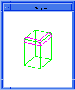  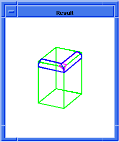
Figure. blend:make-ss-sheet
|
[Top]
blend:make-wire
- Action
-
Executes the second phase of blending which creates a wire intersection.
-
Filename
-
scm/scmext/blnd/blndtest.cpp
-
APIs
-
api_make_blend_wire
-
Syntax
-
(blend:make-wire sheet body [acis-opts])
-
Arg Types
-
-
Returns
-
body
Description
The first phase of blending creates a blend sheet, which is the input argument sheet.
This second phase of blending calls the boolean phase one to create an
intersection boolean.
This extension creates a wire body that represents the intersection of the blend
sheet with the body being blended.
- Arguments
-
sheet
is an input blend sheet.
-
body
is a wire body that represents the intersection of the blend sheet with the
body being blended.
-
acis-opts
contains optional parameters that are specific to the component and general
ACIS options such as the journal and version information. The option argument
(must be the last argument) is a class derived from acis-options.
; blend:make-wire
; First stage of blending.
; Create a solid block.
(define block1
(solid:block (position -20 -20 -20)
(position 5 15 20)))
;; block1
; Get a list of the solid blocks edges.
(define edges1 (entity:edges block1))
;; edges1
; Attach constant radius blend to 2 connected edges.
(define list1
(list (car edges1)
(car (cdr (cdr (cdr edges1))))))
;; list1
(define attach (blend:const-rad-on-edge list1 5))
;; attach
; (#[entity 3 1] #[entity 6 1])
(define sheet1
(blend:make-sheet (car list1)))
;; sheet1
; Second stage of blending.
(define wire1 (blend:make-wire sheet1 block1))
;; wire1
|
[Top]
blend:network
- Action
-
Creates blends on a list of edges and vertices that make up a single blend
network.
-
Filename
-
scm/scmext/blnd/blnd_scm.cpp
-
APIs
-
api_fix_blends
-
Syntax
-
(blend:network entity-list [acis-opts])
-
Arg Types
-
-
Returns
-
body
Description
Accepts a list of edges or vertices owned by a solid body. The entity-list
needs to have blending attributes already be attached. If the
entity-list
argument is indeed a list, its members must be from a single solid body and
must form a blend network. The extension completes the blend and returns the
owning body.
- Arguments
-
entity-list
is a list of edges or vertices owned by a solid body.
-
acis-opts
contains journaling and versioning information.
; blend:network
; Create a solid block.
(define block1
(solid:block (position -20 -20 -20)
(position 20 20 20)))
;; block1
; Get a list of the solid blocks edges.
(define list1 (entity:edges block1))
;; list1
; Define two specific edges in a list.
(define short-list
(list (car list1)
(car (cdr (cdr (cdr list1))))))
;; short-list
; (#[entity 3 1] #[entity 6 1])
; OUTPUT Original
; Attach a constant radius blend to two edges.
(define blend (blend:const-rad-on-edge short-list 5))
;; blend
; Blend the edges and vertices.
(define network (blend:network short-list))
;; network
; OUTPUT Result
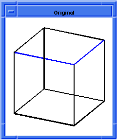  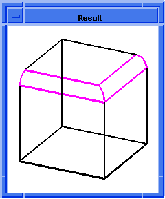
Figure. blend:network
|
[Top]
blend:on-vertex
- Action
-
Attaches vertex blend attributes to each vertex in the input list.
-
Filename
-
scm/scmext/blnd/blnd_scm.cpp
-
APIs
-
None
-
Syntax
-
(blend:on-vertex entity-list [setback=-1 [bulge=1]] |
-
[flag [bulge]])
-
Arg Types
-
-
Returns
-
vertex
| vertex
...
Description
This extension attaches vertex blend attributes to each vertex in the input
entity-list. The optional setback
argument is a distance from the vertex to the start of the blended edge.
setback
changes the setback value on any blended edge leading into the vertex. The
default value indicates the edge setback is not changed.
If the logical
flag
is set to #t then auto-setback is performed. Setbacks are computed and applied
to each edge of the vertex. Setback values depend on the geometry of the body
local to the blended vertex and on the sizes of blends already assigned to
edges ending in the vertex.
This extension returns the input list.
- Arguments
-
entity-list
is a list of input entities.
-
setback
argument is a distance from the vertex to the start of the blended edge.
-
bulge
controls the fullness of the vertex blend. It must range from 0 to 2. The
default value is suitable for most blends.
-
flag
is set to #t then auto-setback is performed.
; blend:on-vertex
; Create a solid block.
(define block1
(solid:block (position -20 -20 -20)
(position 20 20 20)))
;; block1
; Get a list of the solid blocks edges.
(define list1 (entity:edges block1))
;; list1
; Create a short list of edges.
(define short-list
(list (car list1)
(car (cdr (cdr (cdr list1))))
(car (cdr (cdr (cdr (cdr (cdr (cdr (cdr (cdr
(cdr list1))))))))))))
;; short-list
; Get a list of the solid blocks vertices.
(define vert1 (entity:vertices block1))
;; vert1
; OUTPUT Original
; Set a constant radius blend for the given edges.
(define radblend (blend:const-rad-on-edge
short-list 5))
;; radblend
; (#[entity 3 1] #[entity 6 1] #[entity 12 1])
; Set the vertex blend for one of the vertices.
(define blend (blend:on-vertex (car vert1) 10))
;; blend
; Blend the network of edges and vertices.
(define network (blend:network (car list1)))
;; network
; OUTPUT Result
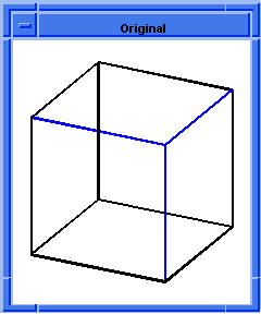  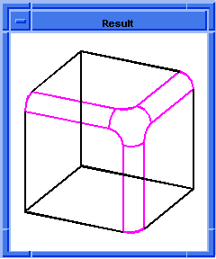
Figure. blend:on-vertex
|
[Top]
blend:preview
- Action
-
Shows a blend network by calculating a quick approximation of the sheet body.
-
Filename
-
scm/scmext/blnd/nblndscm.cpp
-
APIs
-
api_blend_graph
-
Syntax
-
(blend:preview edge)
-
Arg Types
-
-
Returns
-
unspecified
Description
The sheet body is not a valid ACIS body and is deleted after it is drawn out.
Scheme shows approximately the future blend faces associated with the blending
sequence which includes the given edge or vertex
- Arguments
-
edge
is an input edge or vertex.
-
Limitations
-
Currently only available for DI.
; blend:preview
; Create a solid block.
(define block1 (solid:block (position -20 -20 -20)
(position 20 20 20)))
;; block1
; Create a blend sheet.
(blend:round (list-ref
(entity:edges block1) 9) 10 "fix")
;; #t
; Get the list of edges.
(define edges (entity:edges block1))
;; edges
(define ewire (list-ref edges 12))
;; ewire
; Attach const round blend attribute to edge.
(define attach (blend:round ewire 7))
;; attach
; (#[entity 6 1] #[entity 17 1] #[entity 19 1])
; OUTPUT Original
; Do a temporary display of blend network.
(blend:preview ewire)
;; ()
; OUTPUT Preview
; Repair blend network.
(blend:fix ewire)
;; #t
; OUTPUT Result
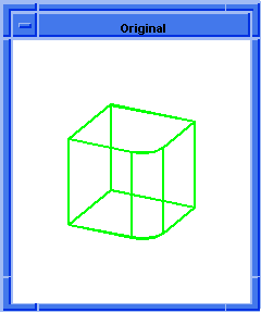
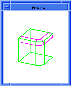  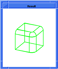
Figure. blend:preview
|
[Top]
blend:remove-from-edge
-
Action
-
Removes blend attributes, if any, from the input edge.
-
Filename
-
scm/scmext/blnd/blnd_scm.cpp
-
APIs
-
None
-
Syntax
-
(blend:remove-from-edge edge)
-
Arg Types
-
-
Returns
-
boolean
Description
This extension removes any blend attributes from the input edge. This extension
returns #t if blend attributes exist and are removed; otherwise, it returns #f.
- Arguments
-
edge
is an input edge from which blend attributes are removed.
; blend:remove-from-edge
; Create a solid block.
(define block1
(solid:block (position -20 -20 -20)
(position 20 20 20)))
;; block1
; Create a list of edges.
(define list1 (entity:edges block1))
;; list1
; Set a constant blend radius for the block.
(blend:const-rad-on-edge list1 5)
;; (#[entity 3 1] #[entity 4 1] #[entity 5 1]
;; #[entity 6 1] #[entity 7 1] #[entity 8 1]
;; #[entity 9 1] #[entity 10 1] #[entity 11 1]
;; #[entity 12 1] #[entity 13 1] #[entity 14 1])
; Get blend information on the first edge.
(blend:edge-info (entity 3 1))
;; (const radius (radius . 5)
;; (setback at start . 0)
;; (setback at end . 0))
; Remove the blend attributes from the edge.
(blend:remove-from-edge (entity 3 1))
;; #t
; Verify that the blend has been removed.
(blend:edge-info (entity 3 1))
;; #f
|
[Top]
blend:remove-from-vertex
- Action
-
Removes blend attributes, if any, from the input vertex.
-
Filename
-
scm/scmext/blnd/blnd_scm.cpp
-
APIs
-
None
-
Syntax
-
(blend:remove-from-vertex vertex)
-
Arg Types
-
-
Returns
-
boolean
Description
This extension removes any blend attributes from the input vertex. It returns
#t if the blend attributes exist and are removed; otherwise, it returns #f.
- Arguments
-
vertex
is an input vertex from which blend attributes are removed.
; blend:remove-from-vertex
; Create a solid block.
(define block1
(solid:block (position -20 -20 -20)
(position 20 20 20)))
;; block1
; Create a vertex list.
(define list1 (entity:vertices block1))
;; list1
; Attach vertex blend attributes to a list.
(blend:on-vertex list1)
;; (#[entity 3 1] #[entity 4 1] #[entity 5 1]
;; #[entity 6 1] #[entity 7 1] #[entity 8 1]
;; #[entity 9 1] #[entity 10 1])
; Get blend information on the first vertex.
(blend:vertex-info (entity 3 1))
;; (vertex (bulge . 1))
; Remove the vertex blend attributes from
; the first edge.
(blend:remove-from-vertex (entity 3 1))
;; #t
; Verify that the blend has been removed.
(blend:vertex-info (entity 3 1))
;; #f
|
[Top]
blend:round
- Action
-
Attaches const round blend attribute to an edge.
-
Filename
-
scm/scmext/blnd/nblndscm.cpp
-
APIs
-
api_blend_graph,
api_fix_blends,
api_set_const_rounds,
api_smooth_edge_seq
-
Syntax
-
(blend:round edge blend-radius
-
[start-setback=0 end-setback=start-setback
-
[start-setback-diff=0 end-setback-diff=start-setback-diff]
-
[start-stop-angle=0 end-stop-angle=start-stop-angle]]]
-
[blend-how=0] ["FIX" | "SINGLE"] [acis-opts])
-
Arg Types
-
-
Returns
-
unspecified
Description
Attaches const round blend attribute on a single edge. Default action is to
place attributes on the smoothly connected edges to the given edge. The last
argument, if given as fix, completes the blend. If given as single, the
attribute is placed on the picked edge only.
Note: blend:round combines blend:ss-sheet,
blend:wire, and blend:complete.
- Arguments
-
edge
is an input single edge on which blend attribute is attached.
-
blend-radius
is radius applied for blending.
-
start-setback
and
end-setback
represent a distance from the vertex to the start of the blended edge.
-
start-setback-diff
and
end-setback-diff
allow the creation of non-circular cross curves. The double represents right
setback - left setback. Refer to
api_set_const_rounds for more details.
-
start-stop-angle
and
end-stop-angle
represent the angle of the capping face used if the setbacks cause the blend to
stop before the end of the edge.
-
blend-how
controls capping versus rollon behavior when the blend encounters another edge
or face.
Values include:
0 = bl_how_default
1 = bl_how_cap
2 = bl_how_roll_on
-
fix
completes the blend.
-
single
places the attribute on the picked edge only.
-
acis-opts
contains journaling and versioning information.
Limitations
Works on a single edge at a time.
; blend:round
; Create a solid block.
(define block1 (solid:block (position -20 -20 -20)
(position 20 20 20)))
;; block1
; OUTPUT Original
; Attach const round blend attribute to edge.
(define blend (blend:round (list-ref
(entity:edges block1) 0) 2 "fix"))
;; blend
; OUTPUT Result
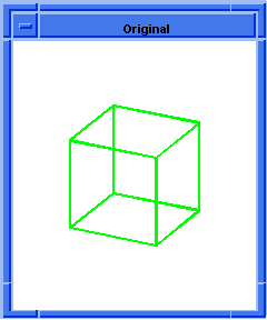  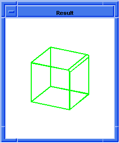
Figure. blend:round
|
[Top]
blend:set-prop
- Action
-
Adds additional information to an existing attribute on a blend edge.
-
Filename
-
scm/scmext/blnd/nblndscm.cpp
-
APIs
-
None
-
Syntax
-
(blend:set-prop edge {prop-name value})
-
Arg Types
-
-
Returns
-
unspecified
Description
Adds additional information to an existing attribute on a blend edge. The
information is specified as a string-value pair. The number of arguments can be
variable and in any order but must be in pairs. Values for
prop-name
can be "start_setback", "end_setback", "start_stop_angle", "end_stop_angle", or
"prefer_edge". The "prefer_edge" argument takes #t or #f. All other arguments
take a value of type real.
- Arguments
-
edge
is an input blend edge to which additional information is added.
-
prop-name
is one of the several parameters which control the shape of the stopped blend
-
value
is a value of the property. -
Limitations
-
Arguments must be provided in pairs.
; blend:set-prop
; Create a block
(define block1 (solid:block
(position -20 -20 -20) (position 30 30 30)))
;; block1
(blend:round (list-ref
(entity:edges block1) 9) 7 "fix")
;; #t
(define entity1 (entity:edges block1))
;; entity1
(define edge1 (list-ref entity1 12))
;; edge1
(define blendround (blend:round edge1 7))
;; blendround
; (#[entity 6 1] #[entity 17 1] #[entity 19 1])
(blend:fix edge1)
;; #t
; OUTPUT Original (roll)
;; -1
(blend:set-prop
edge1 start_setback 7 start_stop_angle 45 )
;; ()
(blend:fix edge1)
;; #t
; OUTPUT Result
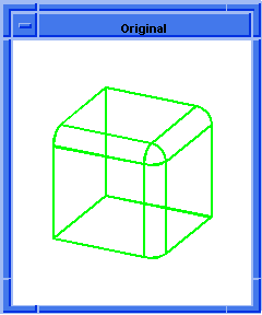  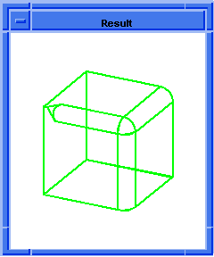
Figure. blend:set-prop
|
[Top]
blend:sheet
-
Action
-
Executes the first phase of blending which creates a blend sheet.
-
Filename
-
scm/scmext/blnd/nblndscm.cpp
-
APIs
-
api_blend_graph,
api_make_blend_sheet
-
Syntax
-
(blend:sheet edge [acis-opts])
-
Arg Types
-
-
Returns
-
body
Description
Builds the sheet body for a given blend network. This, the first stage of
blending, produces the blend geometry.
The created blend sheet contains one or more faces for each blended entity. The
blend body is the body that owns the blended entities. Attributes link the
sheet to the blend body, thereby facilitating the next stage of blending. (In
the next stage of blending, the sheet is combined with the blend body).
The sheet faces lie on new blend surfaces or on surfaces of the blend body where
these are needed to cap blends at ends of blended edges.
Where two blend faces are made for blended edges meeting non-smoothly in an
unblended vertex, the faces are trimmed to one another (i.e., are mitered) and
the sheet faces are joined.
- Arguments
-
edge
is an input blend edge.
-
acis-opts
contains optional parameters that are specific to the component and general
ACIS options such as the journal and version information. The option argument
(must be the last argument) is a class derived from acis-options.
; blend:sheet
; First stage of blending.
; Create a solid block.
(define block1
(solid:block (position -20 -20 -20)
(position 5 15 20)))
;; block1
; Get a list of the solid blocks edges.
(define edges1 (entity:edges block1))
;; edges1
; Attach constant radius blend to 2 connected edges.
(define list1
(list (car edges1)
(car (cdr (cdr (cdr edges1))))))
;; list1
; OUTPUT Original
; Attach constant radius blend to 2 connected edges.
(define attach (blend:const-rad-on-edge list1 5))
;; attach
; (#[entity 3 1] #[entity 6 1])
(define sheet1
(blend:sheet (car list1)))
;; sheet1
; OUTPUT Result
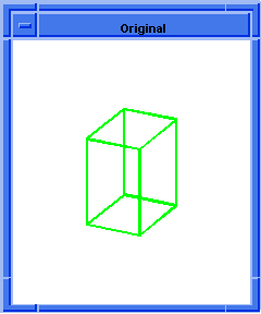  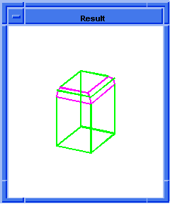
Figure. blend:sheet
|
[Top]
blend:smooth-edges-to-curve
-
Action
-
Constructs a curve entity corresponding to a list of edges typically returned
by blend:get-smooth-edges.
-
Filename
-
scm/scmext/blnd/blnd_scm.cpp
-
APIs
-
api_smooth_edges_to_curve
-
Syntax
-
(blend:smooth-edges-to-curve edge-list [acis-opts])
-
Arg Types
-
-
Returns
-
(entity
...)
Description
This Scheme extension makes a single curve that approximates the given list of
smoothly-connected edges. The input edge list is typically created by the API
api_smooth_edge_seq (see the Scheme command blend:get-smooth-edges).
The list need not be sorted at input.
This Scheme extension can be used in blending to find a defining curve for a
variable-radius blend sequence, which parameterizes the blend surface and
calibrates the radius function.
This Scheme extension returns an entity list containing one curve and two edges
(the curve and the edges corresponding to the start and end of the curve).
- Arguments
-
edge-list
is a given list of smoothly-connected edges.
-
acis-opts
contains optional parameters that are specific to the component and general
ACIS options such as the journal and version information. The option argument
(must be the last argument) is a class derived from acis-options.
; blend:smooth-edges-to-curve
; Create the geometry to illustrate extention.
; Create a solid block and cylinder and unite them.
(define block (solid:block
(position -20 -20 -20) (position 20 20 20)))
;; block
(define cylinder (solid:cylinder
(position 20 0 -20) (position 20 0 20) 20))
;; cylinder
(define my-part (solid:unite block cylinder))
;; my-part
; Get a list of all entities.
(define my-entity-list (part:entities))
;; my-entity-list
; Get the first entity as my-body.
(define my-body (car my-entity-list))
;; my-body
; Get the body transform.
(define my-transf (body:get-transform my-part))
;; my-transf
; Pick an edge on the body and show it in red.
(define def-edge ( pick:edge (ray
(position 10 -20 100) (gvector 0 0 -1))))
;; def-edge
(define red (entity:set-color def-edge RED))
;; red
; Get all edges that are smooth to the selected edge.
(define smooth-edges
(blend:get-smooth-edges def-edge))
;; smooth-edges
; Display them in blue.
(define blue (entity:set-color smooth-edges BLUE))
;; blue
; Construct a curve approximating the smooth edges.
(define smooth
(blend:smooth-edges-to-curve smooth-edges))
;; smooth
; Get the calibration curve.
(define smooth-curve (car smooth))
;; smooth-curve
; Define a position list.
(define position-list (list (position -20 -20 -20)
(position 20 -20 20) (position 20 20 20)
(position -20 20 20)))
;; position-list
; Define a radii list.
(define radii-list (list 8 5 5 8))
;; radii-list
; Build the v-radius object.
(if my-transf
(define v-radius (abl:pos-rad position-list
radii-list smooth-curve my-transf))
(define v-radius (abl:pos-rad position-list
radii-list smooth-curve)))
;; v-radius
; Complete the blend.
(define blend1 (abl:edge-blend def-edge v-radius))
;; blend1
(define blend2 (blend:network
(blend:get-network def-edge)))
;; blend2
|
[Top]
blend:ss-sheet
- Action
-
Calculates the blend sheet one segment at a time.
-
Filename
-
scm/scmext/blnd/nblndscm.cpp
-
APIs
-
api_blend_graph,
api_concl_blend_ss,
api_do_one_blend_ss,
api_init_blend_ss
-
Syntax
-
(blend:ss-sheet edge [acis-opts])
-
Arg Types
-
-
Returns
-
body
Description
Calculates the sheet body for a blend network one segment at a time. The
partially built sheet body is re-drawn after each segment calculation in order
to provide a graphical display of the creation of the blend.
Note: blend:round combines blend:ss-sheet,
blend:wire, and blend:complete.
- Arguments
-
edge
is an input edge.
-
acis-opts
contains journaling and versioning information.
; blend:ss-sheet
; Create a solid block.
(define block1 (solid:block (position 0 0 0)
(position 10 10 10)))
;; block1
; Attach const round blend attribute to edge.
(define attach (blend:round (list-ref
(entity:edges block1) 9) 3))
;; attach
; (#[entity 12 1])
; Calculate the sheet body for a blend network.
(define sheet1 (blend:ss-sheet (list-ref
(entity:edges block1) 9)))
;; sheet1
; Create the blend wire.
(define wire1 (blend:wire (list-ref
(entity:edges block1) 9) sheet1))
;; wire1
; blend edges w, s, and b.
(define complete
(blend:complete wire1 sheet1 block1))
;; complete
; #[entity 2 1]
; Attach const round blend attribute to edge.
(define roundblend (blend:round (list-ref
(entity:edges block1) 12) 2))
;; roundblend
; (#[entity 6 1] #[entity 19 1] #[entity 21 1])
; Calculate the sheet body for a blend network.
(define sheet2 (blend:ss-sheet (list-ref
(entity:edges block1) 12)))
;; sheet2
; Create the blend wire.
(define wire2 (blend:wire (list-ref
(entity:edges block1) 12) sheet2))
;; wire2
; blend edges w, s, and b.
(define complete
(blend:complete wire2 sheet2 block1))
;; complete
; #[entity 2 1]
|
[Top]
blend:var-rad-on-edge
- Action
-
Attaches a variable radius blend attribute to each edge in the input list.
-
Filename
-
scm/scmext/blnd/blnd_scm.cpp
-
APIs
-
api_del_entity,
api_set_var_blends,
api_smooth_edges_to_curve
-
Syntax
-
(blend:var-rad-on-edge entity-list start-radius end-radius
[setback-start=0 setback-end=setback-start]
[start-setback-diff=0 end-setback-diff=start-setback-diff]
[start-stop-angle=0 end-stop-angle=start-stop-angle]]]
[acis-opts]) -
Arg Types
-
-
Returns
-
entity
| entity
...
Description
This extension attaches a variable radius blend attribute to each
EDGE in the input
entity-list. The optional
setback-start
and
setback-end
represent a distance from the vertex to the start of the blended edge. If only
one setback value is provided, it is applied to both
setback-start
and
setback-end.
This extension returns the input entity list.
- Arguments
-
entity-list
is a list of input edge entities to which radius blend attribute is attached.
-
start-radius
and
end-radius
are the radius blend value at the start of edge and end of edge.
-
start-setback
and
end-setback
represent a distance from the vertex to the start of the blended edge.
-
start-setback-diff
and
end-setback-diff
allow the creation of non-circular cross curves. The double represents right
setback - left setback. Refer to
api_set_const_rounds for more details.
-
start-stop-angle
and
end-stop-angle
represent the angle of the capping face used if the setbacks cause the blend to
stop before the end of the edge.
-
acis-opts
contains journaling and versioning information.
; blend:var-rad-on-edge
; Create a solid block.
(define block1
(solid:block (position -20 -20 -20)
(position 30 30 30)))
;; block1
; Create an edge list.
(define list1 (entity:edges block1))
;; list1
; OUTPUT Original
; Set the variable radius blend for an edge.
(define blend
(blend:var-rad-on-edge (car list1) 5 8))
;; blend
; #[entity 3 1]
; Set the variable radius blend for another edge.
(define blendvar (blend:var-rad-on-edge
(car (cdr (cdr (cdr list1)))) 3 2))
;; blendvar
; #[entity 6 1]
; Blend the network of edges.
(blend:fix (car list1))
;; #t
; OUTPUT Result
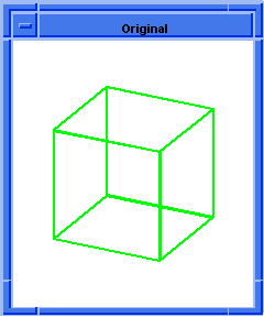  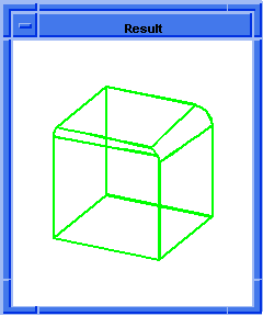
Figure. blend:var-rad-on-edge
|
[Top]
blend:var-round
- Action
-
Attaches variable round blend attributes to a sequence of edges.
-
Filename
-
scm/scmext/blnd/nblndscm.cpp
-
APIs
-
api_blend_graph,
api_fix_blends,
api_set_var_blends,
api_smooth_edge_seq,
api_smooth_edges_to_curve
-
Syntax
-
(blend:var-round edge start-radius end-radius
-
[start-setback=0 end-setback=start-setback
-
[start-setback-diff=0 end-setback-diff=start-setback-diff]
-
[start-stop-angle=0 end-stop-angle=start-stop-angle]]]
-
["FIX" | "SINGLE"] [acis-opts])
-
Arg Types
-
-
Returns
-
unspecified
Description
Attaches variable round blend attributes on a sequence of edges. The default
attaches the attributes on the smoothly connected edges to the given edge. The
last argument, if defined as
fix, completes the blend for the
sequence. If given as
single, the attribute is placed only on
the picked edge (not the sequence). The arguments fix and single may
also be given as f or s.
- Arguments
-
edge
is an input edge to which variable round blend attributes are attached.
-
start-radius
and
end-radius
are the radius blend value at the start of edge and end of edge.
-
start-setback
and
end-setback
represent a distance from the vertex to the start of the blended edge.
-
start-setback-diff
and
end-setback-diff
allow the creation of non-circular cross curves. The double represents right
setback - left setback. Refer to
api_set_const_rounds for more details.
-
start-stop-angle
and
end-stop-angle
represent the angle of the capping face used if the setbacks cause the blend to
stop before the end of the edge.
-
fix
completes the blend for the sequence.
-
single
places the attribute only on the picked edge.
-
acis-opts
contains journaling and versioning information.
; blend:var-round
; Create a block
(define block1 (solid:block
(position -20 -20 -20) (position 30 20 30)))
;; block1
(blend:round (list-ref
(entity:edges block1) 9) 8 "fix")
;; #t
; OUTPUT Original
(define edge1 (entity:edges block1))
;; edge1
(define edge2 (list-ref edge1 12))
;; edge2
(blend:var-round edge2 4 8 "fix")
;; #t
; OUTPUT Result
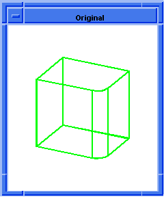  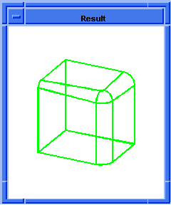
Figure. blend:var-round
|
[Top]
blend:vertex
- Action
-
Attaches blend attribute on a vertex.
-
Filename
-
scm/scmext/blnd/nblndscm.cpp
-
APIs
-
api_set_vblend,
api_set_vblend_auto,
api_set_vblend_autoblend
-
Syntax
-
(blend:vertex vertex {prop-name value} [type] [acis-opts])
-
Arg Types
-
-
Returns
-
unspecified
Description
Attaches a vertex blend attribute on a vertex. Optional properties of the
vertex blend such as bulge and setback can be specified next. The final keyword
type, forces the type of vertex blend
to be made. The values can be "vblend", "autosetback", or "autoblend".
- Arguments
-
vertex
is a vertex to which blend attribute is attached.
-
prop-name
is the optional properties of the vertex blend such as bulge and setback.
-
value
is the property name value.
-
type
is a type of the vertex blend to be made.
-
acis-opts
contains journaling and versioning information.
[Top]
blend:vertex-info
- Action
-
Gets a list of the vertex blend type and internal data values.
-
Filename
-
scm/scmext/blnd/blnd_scm.cpp
-
APIs
-
None
-
Syntax
-
(blend:vertex-info vertex)
-
Arg Types
-
-
Returns
-
(string
. real)
| boolean
Description
This extension tests the specified vertex for blend attributes. It returns a
list containing the blend type and internal data values. If no blend attributes
exist, this extension returns #f.
- Arguments
-
vertex
is an input vertex which will be tested for blend attributes.
; blend:vertex-info
; Create a solid block.
(define block1
(solid:block (position -20 -20 -20)
(position 20 20 20)))
;; block1
; Create a vertex list.
(define list1 (entity:vertices block1))
;; list1
; Attach vertex blend attributes to a list.
(blend:on-vertex list1)
;; (#[entity 3 1] #[entity 4 1] #[entity 5 1]
;; #[entity 6 1] #[entity 7 1] #[entity 8 1]
;; #[entity 9 1] #[entity 10 1])
(blend:vertex-info (car list1))
;; (vertex (bulge . 1))
|
[Top]
blend:wire
- Action
-
Creates the blend wire (second stage of blending).
-
Filename
-
scm/scmext/blnd/nblndscm.cpp
-
APIs
-
api_make_blend_wire
-
Syntax
-
(blend:wire edge sheet [acis-opts])
-
Arg Types
-
-
Returns
-
wire-body
Description
Creates the blend wire, imprints the sheet body with the blank body, and
returns the imprint as a wire body. This is the second stage of blending (blend:sheet
is the first stage).
The first phase of blending (blend:sheet) creates
a blend sheet. The third phase of blending (blend:complete),
calls the boolean phase two to attach the sheet to the blank body using wire.
Note: blend:round combines blend:ss-sheet,
blend:wire, and blend:complete.
- Arguments
-
edge
is an input edge.
-
sheet
is a blending sheet.
-
acis-opts
contains optional parameters that are specific to the component and general
ACIS options such as the journal and version information. The option argument
(must be the last argument) is a class derived from acis-options.
; blend:wire
; Create a solid block.
(define block1
(solid:block (position -20 -20 -20)
(position 5 15 20)))
;; block1
; Get a list of the solid blocks edges.
(define edges1 (entity:edges block1))
;; edges1
; Attach constant radius blend to 2 connected edges.
(define list1
(list (car edges1)
(car (cdr (cdr (cdr edges1))))))
;; list1
; OUTPUT Original
; Attach const round blend attribute to edge.
(define attach (blend:round (car edges1) 5))
;; attach
; (#[entity 3 1])
; Create the blend sheet - first stage of blending.
(define sheet1 (blend:sheet (car list1)))
;; sheet1
; Second stage of blending - create the blend wire.
(define wire1 (blend:wire sheet1 block1))
;; wire1
; OUTPUT Result
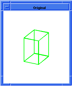  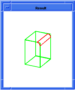
Figure. blend:wire
|
[Top]
solid:blend-edges
- Action
-
Creates a cylindrical blend on a list of edges.
-
Filename
-
scm/scmext/blnd/blnd_scm.cpp
-
APIs
-
api_blend_edges
-
Syntax
-
(solid:blend-edges entity-list radius [acis-opts])
-
Arg Types
-
-
Returns
-
(entity
...)
Description
This extension returns a list of entity owners of all the edges affected by the
blend. In the case where all the edges in the
entity-list
belong to a single solid, this extension returns only one element (the solid).
-
Arguments
-
entity-list
specifies a solid
EDGE entity or a list of solid EDGE entities to be
blended.
-
radius
specifies the length between the faces adjoining the edges.
-
acis-opts
contains optional parameters that are specific to the component and general
ACIS options such as the journal and version information. The option argument
(must be the last argument) is a class derived from acis-options.
; solid:blend-edges
; Create a solid block.
(define block1
(solid:block (position -25 -25 -25)
(position 25 25 25)))
;; block1
; Get a list of the solid blocks edges.
(define edges1 (entity:edges block1))
;; edges1
; OUTPUT Original
; Blend two of the edges.
(define blend (solid:blend-edges (list (car edges1)
(car (cdr (cdr edges1)))) 8))
;; blend
; OUTPUT Result
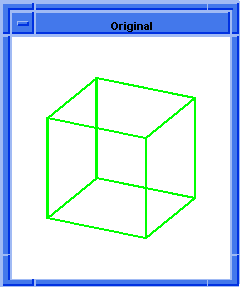  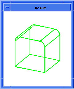
Figure. solid:blend-edges
|
[Top]
solid:chamfer-edges
- Action
-
Creates a chamfer blend on a list of edges.
-
Filename
-
scm/scmext/blnd/blnd_scm.cpp
-
APIs
-
api_chamfer_edges
-
Syntax
-
(solid:chamfer-edges entity-list left-range [right-range] [acis-opts])
-
Arg Types
-
-
Returns
-
(entity
...)
-
Description
-
This extension creates flat chamfers on the given edges with the given left and
right ranges, where left and right correspond to edge direction. Ranges are
always positive. For a chamfer with equal left and right ranges, the points
where the chamfer surfaces meet the faces of the chamfered edge are the same as
those for a round with radius equal to the chamfer range. If the ranges for
left and right differ, the meeting points on the left face are the same as
those for a round with radius equal to the left range, and the meeting points
on the right face are the same as those for a round with radius equal to the
right range.
A list of edges may be specified which creates a series of chamfers between the
faces adjoining the edges.
This extension returns a list of entity owners of all the edges in the
entity-list. If all the edges in the
entity-list
belong to a single solid, this extension returns only one element (the solid).
-
Arguments
-
entity-list
specifies a solid edge entity or list of solid edge entities to be chamfered.
-
left-range
specifies the chamfer range on the left support. If
right-range
is not specified, it is assumed equal to
left-range
-
acis-opts
contains optional parameters that are specific to the component and general
ACIS options such as the journal and version information. The option argument
(must be the last argument) is a class derived from acis-options.
; solid:chamfer-edges
; Create geometry to illustrate this command.
(define block1
(solid:block (position -25 -25 -25)
(position 25 25 25)))
;; block1
; Get a list of the solid blocks edges.
(define edges1 (entity:edges block1))
;; edges1
; OUTPUT Original
; Chamfer two of the solid blocks edges.
(define chamfer-example (solid:chamfer-edges
(list (car (cdr edges1))
(car (cdr (cdr (cdr edges1))))) 10 5))
;; chamfer-example
; OUTPUT Result
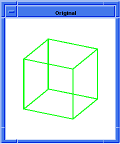  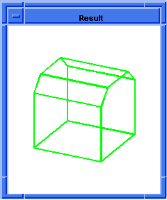
Figure. solid:chamfer-edges
|
[Top]
solid:chamfer-vertex
- Action
-
Creates a planar chamfer on a vertex of a solid body.
-
Filename
-
scm/scmext/blnd/blnd_scm.cpp
-
APIs
-
api_chamfer_vertex
-
Syntax
-
(solid:chamfer-vertex vertex offset1
{[[edge1] [{offsets edges}]*
[distancestraight=#t]] | [chamfernormal]}
[acis-opts]) -
Arg Types
-
-
Returns
-
body
Description
Creates a planar chamfer on a vertex of a solid body.
There are two distinct implementations of this command. One is when offsets are
the distance along the edge(s) and additional edge and offset pairs are
specifically defined (chamfernormal
is not defined). In the second implementation, the chamfer plane is constructed
to be perpendicular to the
chamfernormal
vector and the position of the plane is determined by offsetting from the
vertex along the
chamfernormal. In this case,
chamfernormal
must be specified and no edges or offsets (besides
offset1) are defined. If there are more
than 3 edges touching the vertex and not all of the edge pointers (edge1
or
edges), are specified in the argument
list, all offsets are assumed equal
offset1. This applies even if the
offsets/edges pairs are defined correctly. The three best edges are selected
according to the following algorithm: points are placed on all edges at
offset1
from the vertex and then three such edges are selected. The selected edges all
have the same convexity (at the points location) and these points make the
triangle with the largest perimeter.
When the vertex is the apex of a cone, and
chamfernormal
is not specified,
vertex
and
offset1
are the only arguments needed.
offset1
must be defined as the radius of the sphere with the center at the vertex
(which intersects the cone in order to obtain the intersection curve). This
curve is used to find the location of the chamfer plane, which passes through
the curve.
offset1
can be defined as a negative value to create a concave chamfer (when material
is added to form a chamfer face). Conversely, a positive
offset1
value provides no information about the chamfering type. For example, a
positive
offset1
can be used for removing material from convex vertices and adding material to
concave ones. Therefore, ACIS must detect the chamfering type. When the vertex
does not have adjacent edges, which is only possible with cones and vortex
tori, ACIS analyzes the face sense. For vertices with adjacent edge(s),
convexity of the edge(s) is used to predict the chamfering type. If such a
prediction is impossible (for example, a vertex with mixed-convexity edges) and
offset1
is positive, convex chamfer is assumed.
If
chamfernormal
is specified,
offset1
represents the offset of the chamfer plane from the vertex along the normal.
This implementation of (solid:chamfer-vertex) allows for tilted chamfers on
vertices with zero or one adjacent edge. If
chamfernormal
is not defined,
offset1
represents the offset along the first edge or the radius of an intersection
sphere. Additionally, offset along any edge cannot exceed the length of that
edge and a vertex with 3 edges of mixed convexity may not chamfer successfully.
This extension returns a solid body which owns the chamfered vertex.
solid:chamfer-vertices may serve as a alternative command
choice for chamfering multiple vertices with equal offsets.
- Arguments
-
vertex
is an input vertex.
-
offset1
is a distance from the vertex.
-
distancestraight
is TRUE (default), offsets define the distance along the straight line between
the vertex and the point on the edge. When
distancestraight
is FALSE, offsets define the distance along the edge. The chamfer plane is
positioned to pass through all these points.
distancestraight
has no effect if the edges are straight. As many arguments as necessary may be
supplied, however;
distancestraight
always marks the end of the argument list.
-
acis-opts
contains optional parameters that are specific to the component and general
ACIS options such as the journal and version information. The option argument
(must be the last argument) is a class derived from acis-options. -
Limitations
-
If
chamfernormal
is not defined offset along any edge cannot exceed the length of that edge and
a vertex with 3 edges of mixed convexity may not always chamfer successfully.
When
chamfernormal
is specified and
offset1
is positive, ACIS may fail to detect a concave vertex with edges of mixed
convexity. In this case, use a negative
offset1
value to explicitly specify a concave vertex. When any offset is so large that
the chamfer plane should intersect the faces not containing the vertex,
chamfering is not performed and a chamfer case not implemented error message is
returned.
[Top]
solid:chamfer-vertices
- Action
-
Creates planar chamfers on a list of vertices.
-
Filename
-
scm/scmext/blnd/blnd_scm.cpp
-
APIs
-
api_chamfer_vertices
-
Syntax
-
(solid:chamfer-vertices entity-list offset
[distancestraight=#t] [acis-opts]) -
Arg Types
-
-
Returns
-
(entity
... )
Description
entity-list
specifies a solid vertex entity or a list of solid vertex entities to be
chamfered. offset specifies the chamfer offset to be applied to all edges (if
any) of all vertices.
If there are any edges touching a vertex and
distancestraight
is TRUE, offsets define the distance along the straight line between the vertex
and the point on the edge. When
distancestraight
is FALSE, offsets define the distance along the edge. The chamfer plane is
positioned to pass through all these points.
distancestraight
does not care if the edges are straight.
This extension returns a list of the owners of all the vertices affected by the
chamfering. If all the vertices in the
entity-list
belong to a single solid, this extension returns only one element (the solid).
- Arguments
-
entity-list
specifies a solid vertex entity or a list of solid vertex entities to be
chamfered.
-
offset
specifies the chamfer offset to be applied to all edges (if any) of all
vertices.
-
distancestraight
is TRUE, offsets define the distance along the straight line between the vertex
and the point on the edge. When
distancestraight
is FALSE, offsets define the distance along the edge.
-
acis-opts
contains optional parameters that are specific to the component and general
ACIS options such as the journal and version information. The option argument
(must be the last argument) is a class derived from acis-options. -
Limitations
-
Offset cannot exceed the length of the associated edge. Vertices with 3 edges
of mixed convexity may not chamfer successfully (then, a message chamfer case
not implemented is generated). In this case, solid:chamfer-vertex might be a
better choice.
; solid:chamfer-vertices
; Create geometry to illustrate this command.
(define H 10)
;; H
(define _H (- 0 H))
;; _H
(define block1 (solid:block (position _H _H _H)
(position H H H)))
;; block1
; Get a list of the vertices.
(define vertices1 (entity:vertices block1))
;; vertices1
; OUTPUT Original
; Planar chamfer the vertices of block1.
(define block2 (solid:chamfer-vertices vertices1 H))
;; block2
; OUTPUT Chamfer 1
; Get the list of resulting vertices.
(define vertices2 (entity:vertices block2))
;; vertices2
; Planar chamfer the new list of vertices.
(define chamfer2
(solid:chamfer-vertices vertices2 (/ H 2)))
;; chamfer2
; OUTPUT Result
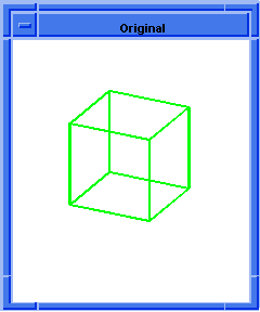  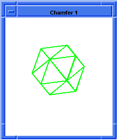
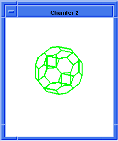
Figure. solid:chamfer-vertices
|
[Top]
solid:flat-on-face
- Action
-
Creates a flat on a given face or faces.
-
Filename
-
scm/scmext/blnd/blnd_scm.cpp
-
APIs
-
api_make_flat_on_faces
-
Syntax
-
(solid:flat-on-face point offset
{face-list | body | normal
[{face-list | body}]} [acis-opts]) -
Arg Types
-
-
Returns
-
body
-
Errors
-
Error messages are generated when a slant flat is placed at the (concave)
center of a vortex torus, erroneous situation of too large offset and/or tilt
is not caught, or a bad body is created.
-
Description
If the intersection of the chamfer plane with the face(s) given by face-list
produces multiple intersection curves (like in the example below), the curve
closest to the projection of the point (first argument) to the chamfer plane,
is used. This extension returns the owner (solid) of all the faces affected by
this operation.
Arguments
-
point
specifies a position in space, which may lie on the face(s) to be modified.
If
face-list
is not defined, point must specify a position which lies on the face(s). If
face-list
is defined, point can specify a position which may not belong to any face.
-
offset
specifies whether the flat is to be accomplished by deleting material (negative
offset) from a convex face or by adding
material to a concave face (positive
offset).
offset
may be positive or negative and determines the offset of a chamfer plane along
its normal. normal may be given as the third argument. If normal is not
specified in the third argument, it defaults as an outward normal of the
face(s) being chamfered at the position nearest to
point
(first argument). Note this sign convention is different from the one used in (solid:chamfer-vertex).
-
normal, if not specified,
face-list
or
body
must be the third parameter to define which faces are to be chamfered. If
body
is given, the point must lie on one or more faces (a point lying on multiple
faces belongs to the intersection of these faces) of the body. The underlying
API function,
api_make_flat_on_faces, then constructs a list of faces to be
chamfered. Finally,
normal
is computed by averaging each of the corresponding outward normals of each face
in face-list.
-
acis-opts
contains optional parameters that are specific to the component and general
ACIS options such as the journal and version information. The option argument
(must be the last argument) is a class derived from acis-options. -
Limitations
-
Making maximum possible flat at the center of a vortex torus, when the chamfer
plane just touches the torus, (i.e., completely filling the toroid indentation
is not possible). Instead, use solid:chamfer-vertex with the central vertices
of the vortex torus.
; solid:flat-on-face
; Create geometry to illustrate command.
; Define the height. Must be greater than two.
(define h 3)
;; h
(define _Pi/2 (/ PI -2))
;; _Pi/2
(define Pi*7/2 (* PI 3.5))
;; Pi*7/2
; Define height. Must be greater than two.
(define h 3)
;; h
; Create solid block using the positions defined
; above.
(define block (solid:block
(position _Pi/2 _Pi/2 (- 0 h))
(position Pi*7/2 Pi*7/2 h)))
;; block
; Define a list of entities and the law to warp them.
(define law (law:warp block vec
(x,y,z+sin (x) +sin (y)) ))
;; law
; Define another block using the same positions as
; above
(define t (solid:block
(position _Pi/2 _Pi/2 (- -3 h))
(position Pi*7/2 Pi*7/2 0)))
;; t
(define subtract (solid:subtract block t))
;; subtract
; OUTPUT Original
(define fof1 (solid:flat-on-face
(position (* PI 2.5) (* PI 2.5)
(+ h 2)) -1.95 block))
;; fof1
(define fof2 (solid:flat-on-face
(position (* PI 0.5) (* PI 0.5) (+ h 2)) -0.25
(gvector -0.5 -0.5 1) block))
;; fof2
(define top_face (pick:face (ray
(position 0 0 (/ (- h 2)2)) (gvector 0 0 1))))
;; top_face
(define fof3 (solid:flat-on-face
(position (* PI 1.5) (* PI 1.5) 1) 1.0
(gvector 0.2 0.3 1) top_face))
;; fof3
(define fof4 (solid:flat-on-face
(position (* PI 0.5) _Pi/2 h) -0.3
(gvector 0.3 -2 1) block))
;; fof4
; Rotate entity for better view of flats.
(define rotate (entity:rotate fof4 1 1 1 45))
;; rotate
; OUTPUT Rotated Result
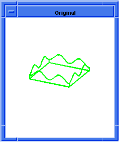  
Figure. solid:flat-on-face
|
[Top]
© 1989-2007 Spatial Corp., a Dassault Systèmes company. All rights reserved.

![]()

