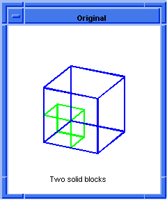
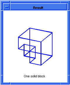
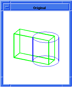
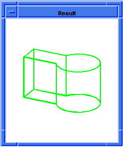
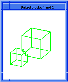
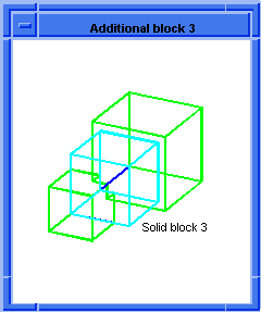
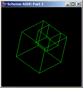
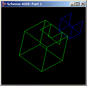
Scheme Extensions
|
|
|
|
Technical Article
|
| Scheme is a public domain programming language, based on the LISP language,
that uses an interpreter to run commands. ACIS provides extensions (written in
C++) to the native Scheme language that can be used by an application to
interact with ACIS through its Scheme Interpreter. The C++ source files for
ACIS Scheme extensions are provided with the product. Spatial's Scheme based
demonstration application, Scheme ACIS Interface Driver Extension (Scheme
AIDE), also uses these Scheme extensions and the Scheme Interpreter.
|
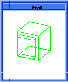
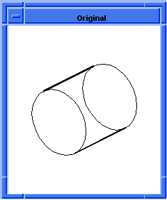
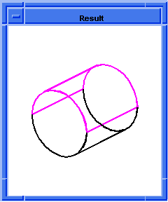
bool:chop
- Action
-
Simultaneously finds the intersection and difference between two bodies.
-
Filename
-
scm/scmext/bool/bool_scm.cpp
-
APIs
-
api_boolean_chop_body
-
Syntax
-
(bool:chop body1 body2 [keep-leftovers=#t] [keep-opt] [bool-opts] [acis-opts])
-
Arg Types
-
-
Returns
-
(entity
...)
Description
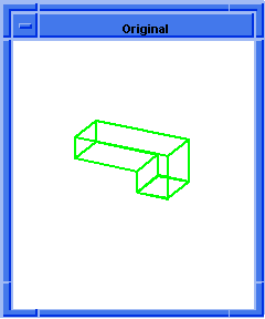
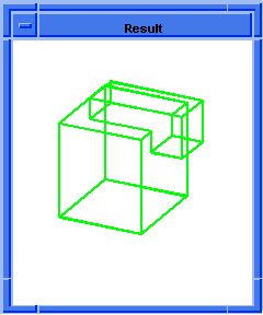
This extension chops the blank body (body1)
with the tool body (body2). The
returned list contains the result of intersecting the two bodies, the result of
subtracting
body2
from
body1, and (possibly) a body containing
any leftovers. Either of the first two bodies returned may be empty. Leftovers
can only exist if the tool body is incomplete. If there is a body containing
leftovers, the
keep-leftovers
argument controls whether it is deleted or not: if
keep-leftovers
is
#f, any leftovers are deleted and the
returned list is always of length 2. If
keep-leftovers
is
#t, the returned list is only of length
3 if there are some leftovers (that is, an empty leftovers body is never
returned).
- Arguments
-
body1
is the blank body.
-
body2
is the tool body.
-
keep-leftovers
controls whether or not the body containing leftovers is deleted
-
keep-opt
is an optional non-destructive Boolean argument that specifies whether
some or all input bodies should be preserved. Allowed values are:
-
-
"keep_blank" - preserve
body1
and return the intersection result of the chop as a new body
"keep_tool" - preserve
body2.
"keep_both" - preserve both input bodies and return the intersection
result of the chop as a new body.
-
bool-opts
specifies Boolean options. Refer to
Bool_Options for more details.
acis-opts
contains parameters for versioning and journaling.
[Top]
bool:clip
- Action
-
Creates a copy of a model clipped to two parallel planes.
-
Filename
-
scm/scmext/bool/bool_scm.cpp
-
APIs
-
api_get_entity_box,
api_slice_of_model
-
Syntax
-
(bool:clip [body-list] [view=active] [hither=SPAresabs] [yon] [acis-opts])
-
Arg Types
-
- Returns
-
(entity
...)
Description
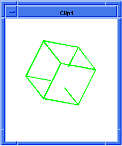
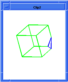
This extension takes an entity list and a view, from which it extracts an eye
position and a non-zero view vector (target eye). It also takes two doubles, hither
and yon, which define two planes orthogonal to the view vector. The
model will be clipped to the hither and yon plane. It first copies the
original, then trims those parts of the entity list that are outside the hither
and yon planes. The trimmed copy is passed back.
As default values, it uses the active part and the active view, and sets hither
to
SPAresabs and
yon
large enough to display the whole model. The eye point is at a distance hither
along the view vector from the hither plane and a distance yon along the
view vector from the yon plane.
If the model itself does not need to be trimmed (i.e., it already is completely
contained within the hither-yon slice), then no copy of the model is made. A
pointer to the original model is passed back (instead of a pointer to a copy).
Caution is advised, since the user could delete the original model thinking it
is a copy.
- Arguments
-
body-list
is a list of entities.
-
view
is a view vector which defines the view.
-
hither
and
yon
specify the distance from the eye point to the hither plane and yon plane
respectively.
-
acis-opts
contains parameters for versioning and journaling.
[Top]
bool:complete
- Action
-
Completes a partial Boolean operation between a tool body and a blank body.
-
Filename
-
scm/scmext/bool/bool_scm.cpp
-
APIs
-
api_boolean_chop_complete,
api_boolean_complete
-
Syntax
-
(bool:complete bool-opt [acis-opts])
-
Arg Types
-
-
Returns
-
entity
Description
Suitable for non-destructive Booleans and glue Booleans. Used in conjunction
with bool:start and bool:sel-intersect.
- Arguments
-
bool-type
is a string that specifies the Boolean operation. It can take one of the
following values: "UNION", "SUBTRACTION", "INTERSECTION", "NONREG_UNION",
"NONREG_INTERSECTION", "NONREG_SUBTRACTION", "CHOP", "NONREG_CHOP".
-
acis-opts
contains parameters for versioning and journaling.
; bool:complete
; Create a tool body
(define b1 (solid:block 0 0 0 10 10 10))
;; b1
; Create a blank body
(define b2 (solid:block -5 -5 -5 5 5 5))
;; b2
; Define faces from tool and blank bodies.
(define f1_1 (list-ref (entity:faces b1) 1))
;; f1_1
(define f1_2 (list-ref (entity:faces b1) 2))
;; f1_2
(define f1_3 (list-ref (entity:faces b1) 3))
;; f1_3
(define f2_0 (list-ref (entity:faces b2) 0))
;; f2_0
(define f2_4 (list-ref (entity:faces b2) 4))
;; f2_4
(define f2_5 (list-ref (entity:faces b2) 5))
;; f2_5
(bool:start b1 b2)
;; #t
(bool:sel-intersect (list f1_1 f1_2 f1_3 f1_1 f1_2 f1_3 f1_1 f1_2 f1_3)
(list f2_0 f2_0 f2_0 f2_4
f2_4 f2_4 f2_5 f2_5 f2_5))
;; #[entity 132 1]
(bool:complete "UNION")
;; #[entity 118 1] |
[Top]
bool:complete-imprint
- Action
-
Finishes the operation imprinting curves of intersection of two bodies onto the
faces of bodies.
-
Filename
-
scm/scmext/bool/bool_scm.cpp
-
APIs
-
api_imprint_complete
-
Syntax
-
(bool:complete-imprint tool-body blank-body [acis-opts])
-
Arg Types
-
-
Returns
-
boolean.
#t(TRUE) if successful, #f(FALSE) otherwise.
Description
The current intersection graph is imprinted on both bodies. Faces are split.
- Arguments
-
tool-body
is the input tool body.
-
blank-body
is the input blank body.
-
acis-opts
contains parameters for versioning and journaling.
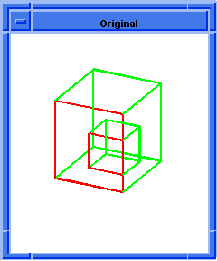
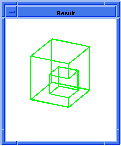
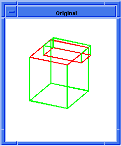
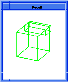
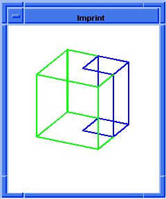
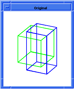
; bool:complete-imprint
; Create two blocks b1 and b2
(define b1 (solid:block 0 0 0 10 10 10))
;; b1
(define b2 (solid:block -1 -1 -1 9 9 9))
;; b2
; Color for b1.
(entity:set-color b1 1)
;; ()
; Color for b2
(entity:set-color b2 4)
;; ()
(define f1_1 (list-ref (entity:faces b1) 1))
;; f1_1
(define f1_2 (list-ref (entity:faces b1) 2))
;; f1_2
(define f1_3 (list-ref (entity:faces b1) 3))
;; f1_3
(define f2_0 (list-ref (entity:faces b2) 0))
;; f2_0
(define f2_4 (list-ref (entity:faces b2) 4))
;; f2_4
(define f2_5 (list-ref (entity:faces b2) 5))
;; f2_5
(bool:start b1 b2)
;; #t
(bool:sel-intersect (list f1_1 f1_1 f1_1 f1_2 f1_2 f1_2 f1_3 f1_3 f1_3)
(list f2_0 f2_4 f2_5 f2_0
f2_4 f2_5 f2_0 f2_4 f2_5))
;; #[entity 15 1]
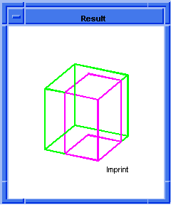
; Complete the imprint.
(bool:complete-imprint b1 b2)
;; #t
; Separate the bodies to see the result.
(entity:transform b1 (transform:translation (gvector 10 10 10)))
;; #[entity 1 1]
; Rebuild the graphic display.
(render:rebuild)
;; () |
[Top]
bool:complete-imprint-stitch
- Action
-
Finishes the operation stitching two bodies.
-
Filename
-
scm/scmext/bool/bool_scm.cpp
-
APIs
-
api_imprint_stitch_complete
-
Syntax
-
(bool:complete-imprint-stitch tool-body blank-body [acis-opts])
-
Arg Types
-
-
Returns
-
boolean.
#t(TRUE) if successful, #f(FALSE) otherwise.
Description
This routine imprints the bodies and then stitches them along the face-face
intersection curves (imprint edges). It gives the same result as imprinting the
two bodies and then stitching them but is faster because the imprint edges are
saved and used directly, instead of detecting compatible edges anew in stitch.
Face normals and coedge senses need not be compatible for attempted stitching
of open solid-bounding shells along edges.
- Arguments
-
tool-body
is the input tool body.
-
blank-body
is the input blank body.
-
acis-opts
contains parameters for versioning and journaling.
; bool:complete-imprint-stitch
; Create a solid block
(define b1(solid:block (position -20 -20 -20) (position 20 20 20)))
;; b1
(define faces (entity:faces b1))
;; faces
; Make a hole in the block.
(define uncover (face:uncover (list-ref faces 5)))
;; uncover
(define b2 (entity:copy b1))
;; b2
(entity:transform b2 (transform:rotation (position 0 0 0)
(gvector 0 0
1) 180))
;; #[entity 8 1]
(entity:transform b2 (transform:translation (gvector 40 0 0)))
;; #[entity 8 1]
(bool:start b2 b1)
;; #t
(define f_1_0 (list-ref (entity:faces b1) 0))
;; f_1_0
(define f_1_1 (list-ref (entity:faces b1) 1))
;; f_1_1
(define f_1_2 (list-ref (entity:faces b1) 2))
;; f_1_2
(define f_1_4 (list-ref (entity:faces b1) 4))
;; f_1_4
(define f_2_0 (list-ref (entity:faces b2) 0))
;; f_2_0
(define f_2_1 (list-ref (entity:faces b2) 1))
;; f_2_1
(define f_2_2 (list-ref (entity:faces b2) 2))
;; f_2_2
(define f_2_4 (list-ref (entity:faces b2) 4))
;; f_2_4
; Perform the local intersections.
(bool:sel-intersect (list f_2_0 f_2_2 f_2_4 f_2_0 f_2_1 f_2_4
f_2_1
f_2_2 f_2_4 f_2_0 f_2_1 f_2_2)
(list f_1_0 f_1_0 f_1_0
f_1_2 f_1_2 f_1_2
f_1_1
f_1_1 f_1_1 f_1_4 f_1_4 f_1_4))
;; #[entity 14 1]
; Complete the imprint stitch.
(bool:complete-imprint-stitch b2 b1)
;; #t
; Rebuild the graphic display.
(render:rebuild)
;; () |
[Top]
bool:complete-inter-graph
- Action
-
Assembles the intersection graph between two bodies computed by previous
partial Boolean operations.
-
Filename
-
scm/scmext/bool/bool_scm.cpp
-
APIs
-
api_complete_intersection_graph
-
Syntax
-
(bool:complete-inter-graph tool-body blank-body [acis-opts])
-
Arg Types
-
-
Returns
-
boolean.
#t(TRUE) if successful, #f(FALSE) otherwise.
Description
Completes the slice between two bodies containing Boolean attributes and ready
to be imprinted. Use in conjunction with bool:start
and bool:sel-intersect. The
intersection graph is returned as a specialized wire body.
- Arguments
-
tool-body
is the input tool body.
-
blank-body
is the input blank body.
-
acis-opts
contains parameters for versioning and journaling. -
Limitations
-
The intersection graph is not a valid body. It represents the specialized wire
that is ready to be imprinted. This Scheme extension is purely designed for
debugging purposes and the result is not intended for modeling operations. See
bool:complete-slice to get a wire body suitable for general
modeling.
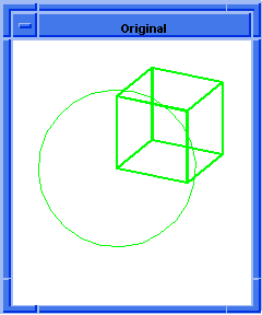
; bool:complete-inter-graph
(part:clear)
;; #t
; Create a body to slice.
(define b1 (solid:block -10 -10 -10 10 10 30))
;; b1
(define b2 (solid:block -10 -10 0 5 5 10))
;; b2
(solid:subtract b1 b2)
;; #[entity 2270 1]
(define c1 (solid:cylinder 0 0 -20 0 0 50 1))
;; c1
(entity:set-color b1 1)
;; ()
(entity:set-color c1 1)
;; ()
; Initialize the operation.
(bool:start c1 b1)
;; #t
; Define all the faces to intersect.
(define f_b_0 (list-ref (entity:faces b1) 0))
;; f_b_0
(define f_b_1 (list-ref (entity:faces b1) 1))
;; f_b_1
(define f_t (list-ref (entity:faces c1) 0))
;; f_t
; Selectively intersect the chosen faces.
(bool:sel-intersect (list f_t f_t) (list f_b_0 f_b_1))
; Now return the slice.
(define slice (bool:complete-inter-graph c1 b1))
;; slice |
[Top]
bool:complete-slice
- Action
-
Assembles the intersection graph between two bodies previously computed by
bool:start and bool:sel-intersect,
and returns it as a wire body.
-
Filename
-
scm/scmext/bool/bool_scm.cpp
-
APIs
-
api_slice_complete
-
Syntax
-
(bool:complete-slice tool-body blank-body [acis-ops])
-
Arg Types
-
-
Returns
-
boolean.
#t(TRUE) if successful, #f(FALSE) otherwise.
Description
Completes the slice between two bodies. Returns a wire body designed for
general use. It does not contain any Boolean attributes.
- Arguments
-
tool-body
is the input tool body.
-
blank-body
is the input blank body.
-
acis-ops
contains parameters for versioning and journaling.
; bool:complete-slice
(part:clear)
;; #t
; Create a body to slice.
(define b1 (solid:block -10 -10 -10 10 10 30))
;; b1
(define b2 (solid:block -10 -10 0 5 5 10))
;; b2
(solid:subtract b1 b2)
;; #[entity 2270 1]
(define c1 (solid:cylinder 0 0 -20 0 0 50 1))
;; c1
(entity:set-color b1 1)
;; ()
(entity:set-color c1 1)
;; ()
; Initialize the operation.
(bool:start c1 b1)
;; #t
; Define all the faces to intersect.
(define f_b_0 (list-ref (entity:faces b1) 0))
;; f_b_0
(define f_b_1 (list-ref (entity:faces b1) 1))
;; f_b_1
(define f_t (list-ref (entity:faces c1) 0))
;; f_t
; Selectively intersect the chosen faces.
(bool:sel-intersect (list f_t f_t) (list f_b_0 f_b_1))
; Now return the slice.
(define slice (bool:complete-slice c1 b1))
;; slice |
[Top]
bool:embed-wire
-
Action
Embeds a
coincident wire in one or more faces of another body. -
Filename
-
scm/scmext/bool/wifaimp.cpp
-
APIs
-
api_embed_wire_in_faces
-
Syntax
-
(bool:embed-wire wire body [tol=SPAresabs]
[acis-opts])
-
Arg Types
-
-
Returns
-
boolean
Errors
Typical errors
resulting from a Boolean operation.
Description
Embeds the given wire in the faces of another body. This is done with the
assumption that the wire lies exactly in the faces of the other body to within
the specified tolerance, i.e. if a wire edge meets the interior of a face, then
the edge is coincident with the surface of that face to within the given
tolerance. Edges intended to split a face must intersect with the face edges to
within the specified tolerance.
If the wire is not coincident everywhere with the other body to within the
specified tolerance, the results are undefined. A tolerance of less than
SPAresabs will be ignored and treated as
SPAresabs. If a tolerance is used, tolerant geometry may be
introduced.
If the whole body is specified, then it is assumed that each edge of the wire is
coincident with every face that it comes into contact with. If the wire does
come into contact with faces that should not be involved in the embedding, then
the caller must supply a list excluding those faces. Particular care should be
taken when a wire is coincident up to the boundary of one face but it is not
coincident with the adjacent face.
Note that we actually imprint the intersection graph on "both" entities, so the
given wire, for example, might acquire extra vertices where it crosses face
boundaries.
Arguments
wire
is the input wire to be embedded.
body
can be a body or face list (if the faces involved are known) in which the wire
is embedded.
tol
is the user-defined tolerance for coincidence between the wire and the faces.
acis-opts
contains journaling and versioning information.
Limitations
The
input wire must be coincident with the other body to within the specified
tolerance, otherwise the results are undefined. The faces must all belong to the
same body.
; bool:embed-wire
; Create a solid block
(define b
(solid:block (position -30 -30 -30)
(position 30 30 30)))
;; b
; Create a wire body from an edge.
(define lin
(edge:linear (position -40 -30 -10)
(position 40 -30 10)))
;; lin
(define w (wire-body lin))
;; w
; Embed the wire in the block
(bool:embed-wire w b)
;; #t
(entity:check b)
;; checked:
;; 1 lumps
;; 1 shells
;; 0 wires
;; 7 faces
;; 7 loops
;; 30 coedges
;; 15 edges
;; 10 vertices
;; ()
|
[Top]
bool:glue-subtract
-
Action
-
Performs a subtraction on two bodies that have a set of overlapping, coincident
faces and no penetrating face-face intersections.
-
Filename
-
scm/scmext/bool/glue_scm.cpp
-
APIs
-
api_boolean_glue
-
Syntax
-
(bool:glue-subtract body1 body2 faces1 faces2 [glue-opts | name-of-option
value ...] [keep-opt] [acis-opts])
-
Arg Types
-
-
Returns
-
body
Description
This extension performs a Boolean subtract operation on two bodies in the
special case where the intersection graph (see solid:slice)
lies precisely on a set of overlapping, coincident faces, and neither body
penetrates the faces of the other body.
This operation is designed to increase performance over the general Boolean
operation, bool:subtract.
Two faces are coincident if the intersection of their interior point sets is
non-empty and bounded by the edges of either face, and on this overlap, their
surface geometries are coincident.
The glue operation performs only those face-face intersections deemed necessary
by the list of pair-wise coincident faces, faces1 and faces2, of body1
and body2 respectively. There is no verification that each pair of faces
is, indeed, coincident, so it is essential that these lists are accurate and
complete.
Refer to glue:options for information on the
options designed to enhance performance. The options may be specified directly
or in a Scheme object.
- Arguments
-
body1
and
body2
are two bodies, where the intersection graph lies precisely on a set of
overlapping, coincident faces, and neither body penetrates the faces of the
other body.
-
faces1
and
faces2
are the faces of
body1
and
body2
respectively.
-
glue-opts
options designed to enhance performance.
-
name-of-option
is the name of a glue option. Possible names are "patch_and_face_cover",
"blank_patches_strict_cover", "single_face_patch" and "non-trivial".
-
value
is the corresponding value of
name-of-option.
-
keep-opt
specifies whether some or all input bodies should be preserved.
-
acis-opts
contains journaling and versioning information.
[Top]
bool:glue-subtract-inter-graph
- Action
-
Determines the intersection graph in the case of a subtraction on two bodies
that have a set of overlapping, coincident faces and no penetrating face-face
intersections.
-
Filename
-
scm/scmext/bool/glue_scm.cpp
-
APIs
-
api_bool_make_intersection_graph
-
Syntax
-
(bool:glue-subtract-inter-graph body1 body2 faces1 faces2 [glue-opts |
name-of-option value ...] [acis-opts])
-
Arg Types
-
-
Returns
-
body
Description
This extension performs the first step of a Boolean subtract operation on two
bodies in the special case where the intersection graph (see
solid:slice) lies precisely on a set of overlapping,
coincident faces, and neither body penetrates the faces of the other body.
This operation is designed to increase performance over the general computation
of a Boolean operation intersection graph, solid:inter-graph.
Two faces are coincident if the intersection of their interior point sets is
non-empty and bounded by the edges of either face, and on this overlap, their
surface geometries are coincident.
The glue operation performs only those face-face intersections deemed necessary
by the list of pair-wise coincident faces, faces1 and faces2, of body1
and body2 respectively. There is no verification that each pair of faces
is, indeed, coincident, so it is essential that these lists are accurate and
complete.
Refer to glue:options for information on the
options designed to enhance performance. The options may be specified directly
or in a Scheme object.
- Arguments
-
body1
and
body2
are two bodies, where the intersection graph lies precisely on a set of
overlapping, coincident faces, and neither body penetrates the faces of the
other body.
-
faces1
and
faces2
are the faces of
body1
and
body2
respectively.
-
glue-opts
options designed to enhance performance.
-
name-of-option
is the name of a glue option. Possible names are "patch_and_face_cover",
"blank_patches_strict_cover", "single_face_patch" and "non-trivial".
-
value
is the corresponding value of
name-of-option.
-
acis-opts
contains journaling and versioning information.
; bool:glue-subtract-inter-graph
; Create the entities
(define block1 (solid:block (position -20 -20 -20)
(position 20 25 25)))
;; block1
(define block2 (solid:block (position -10 -20 15)
(position 10 15 25)))
;; block2
(define faces1 (entity:faces block1))
;; faces1
(define faces2 (entity:faces block2))
;; faces2
(define f10 (list-ref faces1 0))
;; f10
(define f12 (list-ref faces1 2))
;; f12
(define f20 (list-ref faces2 0))
;; f20
(define f22 (list-ref faces2 2))
;; f22
(env:set-highlight-color 1)
;; ()
(entity:set-highlight (list f10 f20) #t)
;; (#[entity 3 1] #[entity 9 1])
(entity:set-highlight (list f12 f22) #t)
;; (#[entity 5 1] #[entity 11 1])
(define glue-opts (glue:options "patch_and_face_cover" #t
"blank_patches_strict_cover" #t
"non_trivial" #t))
;; glue-opts
(bool:start block1 block2)
;; #t
(bool:glue-subtract-inter-graph block1 block2 (list f10 f12)
(list f20 f22) glue-opts)
;; #[entity 30 1]
(bool:complete "SUBTRACTION")
;; #[entity 1 1]
(entity:check block1 70)
;; checked:
;; 1 lumps
;; 1 shells
;; 0 wires
;; 10 faces
;; 10 loops
;; 48 coedges
;; 24 edges
;; 16 vertices
;; () |
[Top]
bool:glue-unite
- Action
-
Unites two bodies that have a set of overlapping, coincident faces and no
penetrating face-face intersections.
-
Filename
-
scm/scmext/bool/glue_scm.cpp
-
APIs
-
api_boolean_glue
-
Syntax
-
(bool:glue-unite body1 body2 faces1 faces2 [glue-opts | name-of-option value
...][keep-opt] [acis-opts])
-
Arg Types
-
-
Returns
-
body
Description
This extension performs a Boolean unite operation on two bodies in the special
case where the intersection graph (see solid:slice)
lies precisely on a set of overlapping, coincident faces, and neither body
penetrates the faces of the other body. This operation is designed to
increase performance over the general Boolean operation,
bool:unite.
Intuitively, this operation (when non-trivial) can be viewed as gluing two solid
objects together by pasting their coincident faces.
Two faces are coincident if the intersection of their interior point sets is
non-empty and bounded by the edges of either face, and on this overlap, their
surface geometries are coincident.
The glue operation performs only those face-face intersections deemed necessary
by the lists of pair-wise coincident faces, faces1 and faces2, of body1
and body2 respectively. It is essential that the lists are accurate and
complete because there is no verification that each pair of faces is
coincident.
Refer to glue:options for information on the
options designed to enhance performance. The options may be specified directly
or in a Scheme object.
- Arguments
-
body1
and
body2
are two bodies, where the intersection graph lies precisely on a set of
overlapping, coincident faces, and neither body penetrates the faces of the
other body.
-
faces1
and
faces2
are the faces of
body1
and
body2
respectively.
-
glue-opts
options designed to enhance performance.
-
name-of-option
is the name of a glue option. Possible names are "patch_and_face_cover",
"blank_patches_strict_cover", "single_face_patch" and "non-trivial".
-
value
is the corresponding value of
name-of-option.
-
keep-opt
specifies whether some or all input bodies should be preserved.
-
acis-opts
contains journaling and versioning information.
[Top]
bool:glue-unite-inter-graph
- Action
-
Determines the intersection graph in the case of a union on two bodies that
have a set of overlapping, coincident faces and no penetrating face-face
intersections.
-
Filename
-
scm/scmext/bool/glue_scm.cpp
-
APIs
-
api_bool_make_intersection_graph
-
Syntax
-
(bool:glue-unite-inter-graph body1 body2 faces1faces2 [glue-opts |
name-of-option value ...][acis-opts])
-
Arg Types
-
-
Returns
-
body
Description
This extension performs the first step of the Boolean unite operation on two
bodies in the special case where the intersection graph (see
solid:slice) lies precisely on a set of overlapping,
coincident faces, and neither body penetrates the faces of the other body.
This operation is designed to increase performance over the general computation
of a Boolean operation intersection graph, solid:inter-graph.
Intuitively, this operation (when non-trivial) can be viewed as gluing two solid
objects together by pasting their coincident faces.
Two faces are coincident if the intersection of their interior point sets is
non-empty and bounded by the edges of either face, and on this overlap, their
surface geometries are coincident.
The glue operation performs only those face-face intersections deemed necessary
by the lists of pair-wise coincident faces, faces1 and faces2, of body1
and body2 respectively. It is essential that the lists are accurate and
complete because there is no verification that each pair of faces is
coincident.
Refer to glue:options for information on the
options designed to enhance performance. The options may be specified directly
or in a Scheme object.
- Arguments
-
body1
and
body2
are two bodies, where the intersection graph lies precisely on a set of
overlapping, coincident faces, and neither body penetrates the faces of the
other body.
-
faces1
and
faces2
are the faces of
body1
and
body2
respectively.
-
glue-opts
options designed to enhance performance.
-
name-of-option
is the name of a glue option. Possible names are "patch_and_face_cover",
"blank_patches_strict_cover", "single_face_patch" and "non_trivial".
-
value
is the corresponding value of
name-of-option.
-
acis-opts
contains journaling and versioning information.
; bool:glue-unite-inter-graph
; Create the entities
(define block1 (solid:block (position -10 -10 25) (position 35 10 35)))
;; block1
(define block2 (solid:block (position 20 -10 15) (position 35 10 25)))
;; block2
(define faces1 (entity:faces block1))
;; faces1
(define faces2 (entity:faces block2))
;; faces2
(define f11 (list-ref faces1 1))
;; f11
(define f20 (list-ref faces2 0))
;; f20
(env:set-highlight-color 1)
;; ()
(entity:set-highlight (list f11 f20) #t)
;; (#[entity 18 1] #[entity 23 1])
(define g (glue:options "non_trivial" #t))
;; g
(bool:start block1 block2)
;; #t
(bool:glue-unite-inter-graph block1 block2 (list f11) (list f20) g)
;;
(bool:complete UNION)
;; #[entity 15 1]
(entity:check block1 70) |
[Top]
bool:intersect
- Action
-
Intersects two or more bodies.
-
Filename
-
scm/scmext/bool/bool_scm.cpp
-
APIs
-
api_boolean
-
Syntax
-
(bool:intersect body1 ... bodyn [keep-opt] [bool-opts] [acis-opts])
-
Arg Types
-
-
Returns
-
body
Description
This extension intersects two or more bodies. The resulting body is the space
that is inside or on all of the input bodies. By default, the result of the
intersection is returned as
body1
and all other bodies are deleted.
This extension performs a regularized intersection. Any faces, edges, and/or
vertices not needed to support the topology of the intersection are removed
before returning the resulting body.
- Arguments
-
body1
is the first body of intersection.
-
bodyn
is the nth body of intersection.
-
keep-opt
specifies whether some or all input bodies should be preserved. Allowed values
are:
-
"keep_blank" preserves
body1
and returns the result of the intersection as a new body.
"keep_tool" preserves
body2
. . .
bodyn.
"keep_both" preserves all input bodies and returns the result of the
intersection as a new body.
-
bool-opts
specifies Boolean options. Refer to
Bool_Options for more details.
-
-
acis-opts
contains parameters for versioning and journaling.
[Top]
bool:join-edges
- Action
-
Joins multiple edges of a body into a single edge.
-
Filename
-
scm/scmext/bool/bool_scm.cpp
-
APIs
-
api_join_edges
-
Syntax
-
(bool:join-edges edgelist [joinC1=#t] [acis-opts])
-
Arg Types
-
-
Returns
-
edge
Description
This extension takes a list of edges in a body and attempts to join them into a
single edge even if the underlying geometries of the edges are different. Edges
must meet end to end in a tangent continuous fashion, and only two edges should
meet at each "interior" vertex.
- Arguments
-
edgelist
is a list of edges in a body.
-
joinC1
specifies whether the resulting edge should be made C1 continuous.
-
acis-opts
contains parameters for versioning and journaling. -
Limitations
-
Edges cannot be branched at the "interior" vertices.
; bool:join-edges
; Create/build geometry to demonstrate command.
; Create 3 edges.
(define edge1 (edge:linear (position 0 0 0)
(position 50 0 0) ))
;; edge1
(define edge2
(edge:circular (position 50 25 0) 25 -90 90))
;; edge2
(define edge3 (edge:linear (position 50 50 0)
(position 0 50 0)))
;; edge3
; Create a wire body that includes all three edges.
(define w (wire-body (list edge1 edge2 edge3)))
;; w
(length (entity:edges w))
;; 3
; Find the edges of the wire body.
(define getedges (entity:edges w))
;; getedges
; Join the edges into a single edge.
(define join (bool:join-edges getedges))
;; join
(length (entity:edges w))
;; 1
|
[Top]
bool:merge
- Action
-
Combines faces and edges of equivalent geometry.
-
Filename
-
scm/scmext/bool/bool_scm.cpp
-
APIs
-
api_clean_entity
-
Syntax
-
(bool:merge entity [acis-opts])
-
Arg Types
-
-
Returns
-
entity
Description
Checks the geometric definitions of a body, face, or edge and merges adjacent
faces when they have an equivalent definition. Faces are merged if they are
adjacent, have equivalent geometry, and have the same sense. Faces are merged
by removing edges. Edges may be removed if they have the same surface on either
side of the edge. A vertex may be removed if all of its associated edges are
removed, if it separates edges which have the same geometrical support, and if
it is not needed to define an end point of another edge.
Note: Vertices on spline edges will not be merged unless the option
merge_spline_vertex is turned on.
- Arguments
-
entity
is an input entity.
-
acis-opts
contains parameters for versioning and journaling.
[Top]
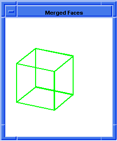
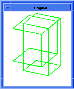
bool:merge-faces
- Action
-
Merges faces on a body by specific type.
-
Filename
-
scm/scmext/bool/bool_scm.cpp
-
APIs
-
api_merge_faces
-
Syntax
-
(bool:merge-faces body [type=plane] [acis-opts])
-
Arg Types
-
-
Returns
-
entity
Description
Merge faces selectively by geometry type. The valid types are plane, cone,
cylinder, sphere and torus.
Checks the geometric definitions of a face and merges adjacent faces when they
have an equivalent definition. Faces are merged if they are adjacent, have
equivalent geometry, and have the same sense. Faces are merged by removing
edges. Edges may be removed if they have the same surface on either side of the
edge. A vertex may be removed if all of its associated edges are removed, if it
separates edges which have the same geometrical support, and if it is not
needed to define an end point of another edge.
- Arguments
-
body
is an input body.
-
type
can be "plane", "cone", "cylinder", "sphere", or "torus".
-
acis-opts
contains parameters for versioning and journaling.
[Top]
bool:merge-list
- Action
-
Merges edges and vertices in a list of entities.
-
Filename
-
scm/scmext/bool/bool_scm.cpp
-
APIs
-
api_clean_list_of_entities
-
Syntax
-
(bool:merge-list entity-list [acis-opts])
-
Arg Types
-
-
Returns
-
() (the empty list)
-
-
Description
-
This Scheme extension takes a list of entities and generates a list of edges
and vertices to merge. Any bodies, lumps, shells, or faces in the given list
are used to generate edges and vertices to be considered for merging. When
topology other than edges or vertices is in the given list, then an edge is
considered for merging if all its incident faces are specified in the list. A
vertex is considered for merging if it is on the boundary of a face or if all
its incident edges are in the list.
Note: Vertices on spline edges will not be merged unless the option
merge_spline_vertex is turned on.
-
- Arguments
-
entity list
is a list of input entities.
-
acis-opts
contains parameters for versioning and journaling.
; bool:merge-list
; Construct a body containing mergeable edges.
(define by (solid:block (position -20 -20 -22) (position 20 20 0)))
;; by
(define bi (solid:block (position -1 -1 -1) (position 1 1 1)))
;; bi
(entity:move bi -1 -1 0)
;; #[entity 2 1]
(bool:nonreg-unite bi (entity:move (entity:copy bi) 0 2 0))
;; #[entity 2 1]
(bool:nonreg-unite bi
(entity:move (entity:copy bi) 2 0 0))
;; #[entity 2 1]
(bool:nonreg-unite bi
(entity:move (entity:copy bi) 4 0 0))
;; #[entity 2 1]
(solid:imprint by bi)
;; #t
(entity:delete bi)
;; ()
; Pick two faces which share an edge.
(ray:queue -1 1 1 0 0 -1 1)
;; #[ray (-1 1 1) (0 0 -1)]
(define fa1 (pick-face))
;; fa1
(ray:queue 1 1 1 0 0 -1 1)
;; #[ray (1 1 1) (0 0 -1)]
(define fa2 (pick-face))
;; fa2
; bool:merge-list merges the edge common to the given pair of faces.
(bool:merge-list (list fa1 fa2))
;; ()
|
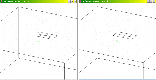
Figure. bool:merge-list
[Top]
bool:nonreg-chop
- Action
-
Simultaneously finds the nonregularized intersection and difference between two
bodies.
-
Filename
-
scm/scmext/bool/bool_scm.cpp
-
APIs
-
api_boolean_chop_body
-
Syntax
-
(bool:nonreg-chop body1 body2 [keep-leftovers= #t] [keep-opt] [bool-opts]
[acis-opts])
-
Arg Types
-
-
Returns
-
list of entities
Description
This extension chops the blank body (body1)
with the tool body (body2). The
returned list contains the result of intersecting the two bodies, the result of
subtracting
body2
from
body1, and (possibly) a body containing
any leftovers. None of these resulting bodies are regularized. Either of the
first two bodies returned may be empty. Leftovers can only exist if the tool
body is incomplete. If there is a body containing leftovers, the
keep-leftovers
argument controls whether it is deleted or not. If
keep-leftovers
is #f, any leftovers are deleted and the returned list is always of length 2.
If
keep-leftovers
is #t, the returned list is only of length 3 if there are some leftovers (that
is, an empty leftovers body is never returned).
- Arguments
-
body1
is a blank body.
-
body2
is a tool body.
-
keep-leftovers
argument controls whether body containing leftovers is deleted or not.
-
keep-opt
is optional and specifies whether one or both input bodies should be
preserved. Allowed values are:
-
"keep_blank" preserves
body1
and returns the result of the intersection as a new body.
"keep_tool" preserves
body2.
"keep_both" preserves both input bodies and returns the result of the chop as
new bodies.
-
bool-opts
specifies Boolean options. Refer to
Bool_Options for more details.
-
-
acis-opts
contains parameters for versioning and journaling.
[Top]
bool:nonreg-intersect
- Action
-
Intersects two or more bodies.
-
Filename
-
scm/scmext/bool/bool_scm.cpp
-
APIs
-
api_boolean
-
Syntax
-
(bool:nonreg-intersect body1 ... bodyn [keep-opt] [bool-opts] [acis-opts])
-
Arg Types
-
-
Returns
-
body
Description
This extension intersects two or more bodies. By default, the result of the
intersection is returned as
body1
and all other bodies are deleted. The input body is trimmed to be only
those parts inside or on all of the input bodies.
After the non-regularized intersection, the returned body may still have faces,
edges, and/or vertices that are not needed to support the topology.
Single-sided faces that become double-sided-both-inside faces, internal faces,
and coincident regions are retained as part of the body. This extension does
not merge edges or vertices at the end of the Boolean.
- Arguments
-
body1
is the first body of intersection.
-
bodyn
is the nth body of intersection.
-
keep-opt
specifies whether some or all input bodies should be preserved. Allowed values
are:
-
"keep_blank" preserves
body1
and returns the result of the intersection as a new body.
"keep_tool" preserves
body2
. ...
bodyn.
"keep_both" preserves all input bodies and returns the result of the
intersection as a new body.
-
bool-opts
specifies Boolean options. Refer to
Bool_Options for more details.
-
acis-opts
contains parameters for versioning and journaling.
[Top]
bool:nonreg-subtract
- Action
-
Subtracts one or more bodies from a body.
-
Filename
-
scm/scmext/bool/bool_scm.cpp
-
APIs
-
api_boolean
-
Syntax
-
(bool:nonreg-subtract body1 ... bodyn [keep-opt] [bool-opts] [acis-opts])
-
Arg Types
-
-
Returns
-
body
Description
This extension subtracts one or more bodies from the first body, and it returns
the result as
body1. The other bodies are deleted.
The optional keep-opt specifies whether some or all input bodies should be
preserved.
This extension performs a non-regularized subtract. The resulting body may have
faces, edges, and/or vertices that are not needed to support the topology.
These are not removed before returning the resulting body.
Single-sided faces that become double-sided-both-inside faces, internal faces,
and coincident regions are retained as part of the body. This extension does
not merge edges or vertices at the end of the Boolean.
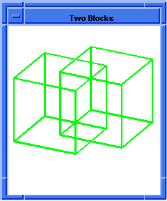
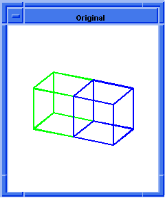
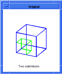
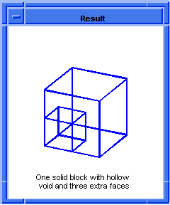
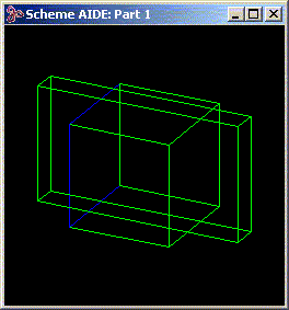
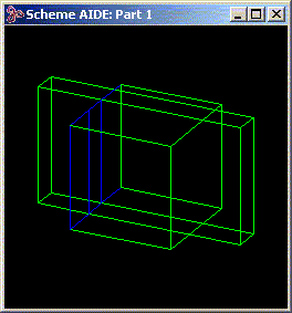
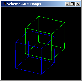
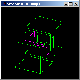
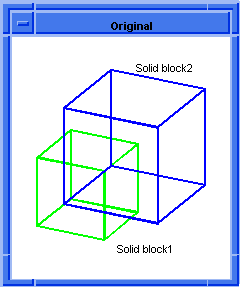
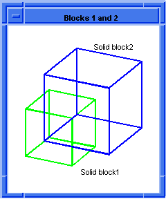
The following example creates two solid blocks that share three common face
regions. The Boolean non-regularized subtract removes the smaller cube from the
larger cube, leaving a 3D void; however, non-regularized Boolean operations
retain coincident regions. The three coincident faces are retained as well. (A
regularized subtract would remove these three faces.)
- Arguments
-
body1
is the first body of subtraction.
-
bodyn
is the nth body of subtraction.
-
keep-opt
specifies whether some or all input bodies should be preserved. Allowed values
are:
-
"keep_blank" preserves
body1
and returns the result of the subtraction as a new body.
"keep_tool" preserves
body2
...
bodyn.
"keep_both" preserves all input bodies and returns the result of the
subtraction as a new body.
-
-
-
bool-opts
specifies Boolean options. Refer to
Bool_Options for more details.
acis-opts
contains parameters for versioning and journaling.
[Top]
bool:nonreg-unite
- Action
-
Unites two or more bodies.
-
Filename
-
scm/scmext/bool/bool_scm.cpp
-
APIs
-
api_boolean
-
Syntax
-
(bool:nonreg-unite body1 ... bodyn [keep-opt] [bool-opts] [acis-opts])
-
Arg Types
-
-
Returns
-
body
Description
This extension unites two or more bodies. By default, the result of the unite
is returned as
body1
and the remaining bodies are deleted.
This extension performs a non-regularized unite. The resulting body may have
faces, edges, and/or vertices not needed to support the topology. These are not
removed before returning the resulting body.
Single-sided faces that become double-sided, both-inside faces, internal faces,
and coincident regions are retained as part of the body. This extension does
not merge edges or vertices at the end of the Boolean.
- Arguments
-
body1
is the first body of unite.
-
bodyn
is the nth body of unite.
-
keep-opt
specifies whether some or all input bodies should be preserved. Allowed values
are:
-
"keep_blank" preserves
body1
and returns the result of the unite as a new body.
"keep_tool" preserves
body2
...
bodyn.
"keep_both" preserves all input bodies and returns the result of the unite as a
new body
-
bool-opts
specifies Boolean options. Refer to
Bool_Options for more details.
-
acis-opts
contains parameters for versioning and journaling.
[Top]
bool:options
- Action
-
Creates or sets the options in the data structure, thus holding information to
be used by boolean operations.
-
Filename
-
scm/scmext/bool/bool_scm.cpp
-
APIs
-
None
-
Syntax
-
(bool:options ["near_coi_fuzz" ncf_value] ["merge_type" merge_str] [bool-opts])
-
Arg Types
-
-
Returns
-
Bool_Options
Description
These options are designed to provide additional information to the Boolean
operations for improved accuracy and performance. The default value for these
options is set to 0, that is, "unset".
This object can be used to specify a "near coincidence fuzz" value. If this
value is set and is greater than resabs, then it is used as a hint to the
Boolean that pairs of entities which are coincident to within the fuzz value
may be regarded as coincident. The Boolean may then force coincidence by adding
tolerances where necessary. Depending on the situation, the fuzz value may be
ignored by the Boolean (for instance, if forcing coincidence would result in
the creation of bad geometry).
Also, the object can also be used to control whether merging is done by the
Boolean ("on | off"), or controlled by a global option ("unset"). In addition,
if no merging is carried out, it controls whether information about the
entities which would have been considered for merging is retained for later use
("delayed"). This last possibility is intended to allow applications to
implement a delayed merge.
Finally, it can also take a pre-existing
Bool_Options object to set.
- Arguments
-
ncf_value
specfiies the value for the "near_coi_fuzz" option. This option affects
how nearly coincident geometry is processed during Boolean operations. The
"near_coi_fuzz" parameter is a real number representing the accuracy of
edge-face and face-face coincidences. It has a value greater than or equal to 0;
the default is 0. The parameter enables the application to tell ACIS
that edge-face near coincidences or face-face near coincidences are intended to
be coincident. ACIS uses the information to create tolerant entities during the
Boolean operation where this is necessary to enforce coincidence of the
entities. If the value of the "near_coi_fuzz" parameter is SPAresabs or
smaller, then SPAresabs is used to determine when two entities are
coincident.
-
merge_str
specifies the value for the "merge_type" option. Valid values include
"unset", "on", "off", or "delayed". The option "merge_type" specifies what
merging is required at the end of a Boolean operation. Non-regularized Booleans
ignore the value of this option. This option is of type string having the
following values:
| on |
merging is performed after the Boolean operation |
| off |
merging is not performed |
| delayed |
the Boolean operation does not perform the merge but makes available a list of
entities to be considered as candidates for merge |
| unset |
merging is controlled by the global option "merge", which is the same behavior
as in previous versions of ACIS. This is the default. |
When the value delayed is given for the merge_type, the return
value of the Boolean operation is a list consisting of the result body and a
list of merge candidates.
Non-regularized Booleans ignore the value of this option. This behavior remains
the same when the Boolean is non-regularized even though the value of this
option has no effect on the result; the list of merge candidates is always
empty.
-
bool-opts
specifies a pre-existing Bool_Options object to set.
-
-
Note: To set the value of an option, simply append
two elements to the list, the first element being the name of the option, the
second its value. The options may occur in any order.
-
-
; bool:options
;; bool:options
; Create bool:options object
(bool:options "near_coi_fuzz" 1.1e-5 "merge_type" "on")
;;#[Bool_Options "near_coi_fuzz" 1.1e-005 "merge_type" bool_merge_on]
|
[Top]
bool:regularise
- Action
-
Regularizes an entity.
-
Filename
-
scm/scmext/bool/bool_scm.cpp
-
APIs
-
api_regularise_entity
-
Syntax
-
(bool:regularise ent [acis-opts])
-
Arg Types
-
-
Returns
-
entity
Description
This extension removes single-sided faces that become double-sided- both-inside
faces, internal faces and coincident regions. This extension also merges edges
and vertices.
- Arguments
-
entity
is an input entity.
-
acis-opts
contains parameters for versioning and journaling.
[Top]
bool:scribe
- Action
-
Scribes an edge in the faces of another body or a wire body.
-
Filename
-
scm/scmext/bool/bool_scm.cpp
-
APIs
-
api_scribe
-
Syntax
-
(bool:scribe entity edge tol split_on_intersections [acis-opts])
-
Arg Types
-
-
Returns
-
entity
Description
This extension scribes an edge in the faces of another body or a wire body.
- Arguments
-
entity
is an input entity.
-
edge
edge in which to scribe on the body, face, or wire.
-
tol
user-defined tolerance for coincidence between the edge and the body.
-
split_on_intersections
splits the edge on any intersection within the body.
-
acis-opts
contains parameters for versioning and journaling.
[Top]
bool:sel-imprint
- Action
-
Imprints the intersection graph of a set of selected faces of the tool body and
a set of selected faces of the blank body onto both bodies.
-
Filename
-
scm/scmext/bool/bool_scm.cpp
-
APIs
-
api_selectively_imprint
-
Syntax
-
(bool:sel-imprint tool-body-or-faces blank-body-or-faces
[split-check=#t][acis-opts])
-
Arg Types
-
-
Returns
-
entity
-
Errors
-
NO_INTSCT: No intersections were found.
IMPROPER_SPLIT: A face was not properly split.
Description
This extension imprints the intersection graph of a set of faces on the tool
body and a set of faces on the blank body onto both bodies. If every face of
one body is to be used, that body may be supplied instead of a list of faces.
When split-check is true, additional checks are performed to ensure that
all edges and vertices imprinted on the blank body contribute to the proper
splitting of faces in the blank body. If they do not (for example, there are
dangling edges imprinted on the faces), then an error is thrown. To allow the
imprint to succeed in such a case, the split-check flag should be set to
#f.
- Arguments
-
tool-body-or-faces
is the tool body or a set of faces on the tool body.
-
blank-body-or-faces
is the blank body or a set of faces on the blank body.
-
acis-opts
contains parameters for versioning and journaling.
[Top]
bool:sel-intersect
- Action
-
Intersects selected faces of a tool body with selected faces of a blank body in
a sequential manner. Used in conjunction with bool:start
and bool:complete.
-
Filename
-
scm/scmext/bool/bool_scm.cpp
-
APIs
-
api_selectively_intersect
-
Syntax
-
(bool:sel-intersect tool-faces blank-faces [acis-opts])
-
Arg Types
-
-
Returns
-
wire-body
Description
Given faces (tf-0, tf-1 ...) of a tool body and faces (bf-0, bf-1 ...) of a
blank body, this extension intersects tf-i with bf-i (where i = 0, 1, 2...).
Note: bool:start must be
called before calling bool:sel-intersect, in order to prepare the
intersection graph.
- Arguments
-
tool-faces
is a set of faces on the tool.
-
blank-faces
are the faces of a blank body.
-
acis-opts
contains parameters for versioning and journaling.
; bool:sel-intersect
; Create a tool body
(define b1 (solid:block 0 0 0 10 10 10))
;; b1
; Create a blank body
(define b2 (solid:block -5 -5 -5 5 5 5))
;; b2
; Define faces from tool and blank bodies.
(define f1_1 (list-ref (entity:faces b1) 1))
;; f1_1
(define f1_2 (list-ref (entity:faces b1) 2))
;; f1_2
(define f1_3 (list-ref (entity:faces b1) 3))
;; f1_3
(define f2_0 (list-ref (entity:faces b2) 0))
;; f2_0
(define f2_4 (list-ref (entity:faces b2) 4))
;; f2_4
(define f2_5 (list-ref (entity:faces b2) 5))
;; f2_5
(bool:start b1 b2)
;; #t
(bool:sel-intersect (list f1_1 f1_2 f1_3 f1_1 f1_2 f1_3 f1_1 f1_2 f1_3)
(list f2_0 f2_0 f2_0 f2_4
f2_4 f2_4 f2_5 f2_5 f2_5))
;; #[entity 132 1]
(bool:complete "UNION")
;; #[entity 118 1] |
[Top]
bool:start
- Action
-
Initializes a partial Boolean operation between a tool body and a blank body.
-
Filename
-
scm/scmext/bool/bool_scm.cpp
-
APIs
-
api_boolean_start
-
Syntax
-
(bool:start tool-body blank-body [acis-opts])
-
Arg Types
-
-
Returns
-
boolean.
#t(TRUE) if successful, #f(FALSE) otherwise.
Description
Used in conjunction with bool:sel-intersect and
bool:complete.
- Arguments
-
tool-body
is the input tool body.
-
blank-body
is the input blank body.
-
acis-opts
contains parameters for versioning and journaling.
; bool:start
; Create a tool body
(define b1 (solid:block 0 0 0 10 10 10))
;; b1
; Create a blank body
(define b2 (solid:block -5 -5 -5 5 5 5))
;; b2
; Define faces from tool and blank bodies.
(define f1_1 (list-ref (entity:faces b1) 1))
;; f1_1
(define f1_2 (list-ref (entity:faces b1) 2))
;; f1_2
(define f1_3 (list-ref (entity:faces b1) 3))
;; f1_3
(define f2_0 (list-ref (entity:faces b2) 0))
;; f2_0
(define f2_4 (list-ref (entity:faces b2) 4))
;; f2_4
(define f2_5 (list-ref (entity:faces b2) 5))
;; f2_5
(bool:start b1 b2)
;; #t
(bool:sel-intersect (list f1_1 f1_2 f1_3 f1_1 f1_2 f1_3 f1_1 f1_2 f1_3)
(list f2_0 f2_0 f2_0 f2_4
f2_4 f2_4 f2_5 f2_5 f2_5))
;; #[entity 132 1]
(bool:complete "UNION")
;; #[entity 118 1] |
[Top]
bool:subtract
- Action
-
Subtracts one or more bodies from a body.
-
Filename
-
scm/scmext/bool/bool_scm.cpp
-
APIs
-
api_boolean
-
Syntax
-
(bool:subtract body1 ... bodyn [keep-opt][bool-opts][acis-opts])
-
Arg Types
-
-
Returns
-
body
Description
This extension subtracts one or more bodies from the first body. By default,
the result of the subtract is returned as body1 and the remaining bodies
are deleted.
The optional
keep-opt
specifies whether some or all input bodies should be preserved.
This extension performs a regularized subtraction. Any faces, edges, and/or
vertices not needed to support the topology are removed before returning the
resulting body.
- Arguments
-
body1
is the first body of subtraction.
-
bodyn
is the nth body of subtraction.
-
keep-opt
specifies whether some or all input bodies should be preserved. Allowed value
are:
-
-
"keep_blank" preserves
body1
and returns the result of the subtraction as a new body.
"keep_tool" preserves
body2
...
bodyn.
"keep_both" preserves all input bodies and returns the result of the
subtraction as a new body.
-
-
-
bool-opts
specifies Boolean options. Refer to
Bool_Options for more details.
acis-opts
contains parameters for versioning and journaling.
[Top]
bool:trim-faces
- Action
-
Trims the surfaces of the given faces.
-
Filename
-
scm/scmext/bool/bool_scm.cpp
-
APIs
-
None
-
Syntax
-
(bool:trim-faces faces [trim] [acis-opts])
-
Arg Types
-
-
Returns
-
(entity
...)
Description
Trims each input face in the following way:
If the surface on which this face lies is parametric, trim it back to the face
boundaries. Whether the trimming is done by subsetting or by splitting the
surface is controlled by the "trim" parameter, which specifies which surface
types should be subset rather than split. This Scheme extension only affects
spline or torus surfaces, and only splines can be split, so the following trim
options are available:
| "all" |
subset both spline and tori, ignore all others
|
| "spline" |
subset splines only, ignore all other types |
| "torus" |
subset tori only, split splines, ignore all others
|
| "none" |
do not subset any surface type, split splines
|
If any surface is not subsetted, it will be split explicitly. Any surface other
than a spline or torus remains as is.
- Arguments
-
face
is an input face.
-
trim
is a different trim options available.
-
acis-opts
contains parameters for versioning and journaling. -
Limitations
-
Only operates on splines and tori. Surface is trimmed to parametric box of
face's pcurves.
; bool:trim-faces
; create solid block.
(define b (solid:block (position 0 0 0)
(position -10 -10 -10)))
;; b
; Trim the surfaces of the defined faces.
(define trim (bool:trim-faces
(entity:faces b) "none"))
;; trim |
[Top]
bool:unite
- Action
-
Unites two or more bodies.
-
Filename
-
scm/scmext/bool/bool_scm.cpp
-
APIs
-
api_boolean
-
Syntax
-
(bool:unite body1 ... bodyn [keep-opt] [bool-opts] [acis-opts])
-
Arg Types
-
-
Returns
-
body
Description
This extension unites two or more bodies. By default, the result of the unite
is returned as
body1
and the remaining bodies are deleted.
This extension checks for overlapping bodies. If it is known that the bodies do
not overlap, use
body:combine, because it does not perform intersection checks.
If it is known that the bodies overlap, or if there is some uncertainty as to
whether the bodies overlap, use bool:unite.
This extension performs a regularized unite. Any faces, edges, and/or vertices
not needed to support the topology are removed before returning the resulting
body.
- Arguments
-
body1
is the first body of unite.
-
bodyn
is the nth body of unite.
-
keep-opt
specifies whether some or all input bodies should be preserved. Allowed values
are:
"keep_blank" preserves body1 and returns the
result of the unite as a new body.
"keep_tool" preserves body2 ... bodyn.
"keep_both" preserves all input bodies and returns the result of the unite as a
new body.
-
bool-opts
specifies Boolean options. Refer to
Bool_Options for more details.
acis-opts
contains parameters for versioning and journaling.
[Top]
bool:unite-wires
- Action
-
Unites the wires of the tool body with the wires of the blank body.
-
Filename
-
scm/scmext/bool/bool_scm.cpp
-
APIs
-
api_unite_wires
-
Syntax
-
(bool:unite-wires blank tool [acis-opts])
-
Arg Types
-
-
Returns
-
body
Description
This Scheme command unites the wires of the tool body with the wires of the
blank body where they meet at common vertices. The result is the blank body.
The tool body is deleted.
- Arguments
-
blank
is a blank body.
-
tool
is an input tool body.
-
acis-opts
parameter can be used for setting the version and journal information.
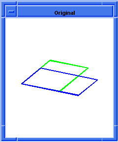
; bool:unite-wires
; Create a tool body
(define t (wire-body:points
(list (position 0 0 0)
(position 1 0 0)
(position 1 1 0)
(position 0 1 0))))
;; t
; Create a blank body
(define b (wire-body:points
(list (position 1 1 0)
(position 1 1 1)
(position 1 2 1)
(position 1 2 0))))
;; b
; Unite the wires of both the bodies
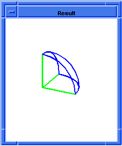
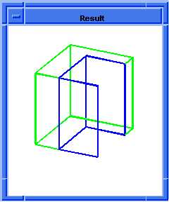
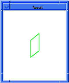
(bool:unite-wires b t)
; OUTPUT Result |
[Top]
bool:update-intersection
- Action
-
Pre-empts a partial Boolean selective intersection when the result is already
known.
-
Filename
-
scm/scmext/bool/bool_scm.cpp
-
APIs
-
api_update_intersection
-
Syntax
-
(bool:update-intersection tool-face [ttransf] blank-face [btransf] int-edges
[check-rels= #t] [acis-opts])
-
Arg Types
-
-
Returns
-
boolean.
#t(TRUE) if successful, #f(FALSE) otherwise.
Description
This routine is passed a tool face and blank face together with a list of edges,
which represent the intersection of the two faces. A
surf_surf_int structure is built using the geometry of these
edges as the intersection of the two surfaces, thereby eliminating the need to
intersect the faces themselves. To record this, an
ATTRIB_FACEINT is attached to the tool face and no
intersection will be performed when these faces are to be intersected
- Arguments
-
tool-face
is the input tool face.
-
ttransf
is the transform for the tool face.
-
blank-face
is the input blank face.
-
btransf
is the transform for the blank face.
-
int-edges
a list of edges that represent the intersection of the two faces.
-
check-rels
indicates whether to check if the intersection edges really lie in the faces.
This can be relatively expensive, so it may be avoided by passing #f, in which
case it is assumed that the edge-face relationships are being guaranteed.
-
acis-opts
contains parameters for versioning and journaling.
; bool:update-intersection
(part:clear)
;; #t
; create solid blocks.
(define b1 (solid:block 0 0 0 10 10 10))
;; b1
(define b2 (solid:block -10 -10 -10 20 20 0))
;; b2
; Fix transforms
(entity:fix-transform b1)
;; #[entity 28 1]
(entity:fix-transform b2)
;; #[entity 29 1]
(define f1_1 (list-ref (entity:faces b1) 1))
;; f1_1
(define f1_2 (list-ref (entity:faces b1) 2))
;; f1_2
(define f1_3 (list-ref (entity:faces b1) 3))
;; f1_3
(define f1_4 (list-ref (entity:faces b1) 4))
;; f1_4
(define f1_5 (list-ref (entity:faces b1) 5))
;; f1_5
(define f2_0 (list-ref (entity:faces b2) 0))
;; f2_0
; Initializes the Boolean operation.
(bool:start b1 b2)
;; #t
; Set the intersection records.
(bool:update-intersection f1_1 f2_0 (entity:edges f1_1))
;; #t
(bool:update-intersection f1_2 f2_0 (cadr (entity:edges f1_2)))
;; #t
(bool:update-intersection f1_3 f2_0 (cadr (entity:edges f1_3)))
;; #t
(bool:update-intersection f1_4 f2_0 (cadr (entity:edges f1_4)))
;; #t
(bool:update-intersection f1_5 f2_0 (cadr (entity:edges f1_5)))
;; #t
(bool:sel-intersect (list f1_1 f1_2 f1_3 f1_4 f1_5)
(list f2_0 f2_0 f2_0 f2_0
f2_0))
;; #[entity 54 1]
; Completes the Boolean operation.
(bool:complete "UNION")
;; #[entity 28 1] |
[Top]
bool:wifa-imp
- Action
-
Obsolete: Use bool:embed-wire
instead.
Imprints a wire on one or more faces of another body. -
Filename
-
scm/scmext/bool/wifaimp.cpp
-
APIs
-
api_embed_wire_in_faces
-
Syntax
-
(bool:wifa-imp edge face-list)
-
Arg Types
-
-
Returns
-
boolean
-
Errors
-
Typical errors resulting from a Boolean operation.
Description
Imprints the given wire or wire edge onto the given face (or faces)
of another. It is assumed that the wire lies exactly in the face (though
the wire might be longer or shorter than the face). If the wire is not
coincident with the face everywhere, the results are undefined.
Note that we actually imprint the intersection graph on both entities, so the
given wire might, for example, acquire extra vertices where it crosses face
boundaries.
- Arguments
-
wire
is the input wire or wire edge.
-
face-list
is the list of input faces to imprint. -
Limitations
-
If an edge is supplied, it must belong to a wire body and be the wire's only
edge. The input wire must lie on the given faces. The faces must all be of the
same body. Otherwise, undefined results.
; bool:wifa-imp
; Create a solid block
(define b (solid:block (position -30 -30 -30)
(position 30 30 30)))
;; b
; Create a wire body from an edge.
(define lin (edge:linear (position -30 -30 -10)
(position 30 -30 10)))
;; lin
(define w (wire-body lin))
;; w
; Select the face along which the wire body lies.
(define fs (entity:faces b))
;; fs
(define f (list-ref fs 2))
;; f
; Select the wire body's (only) edge.
(define es (entity:edges w))
;; es
(define e (car es))
;; e
; Imprint the edge onto the face.
(bool:wifa-imp e f)
;; #t |
[Top]
edge:remove-no-merge-attrib
- Action
-
Removes a
NO_MERGE_ATTRIB attribute from each edge in the input list of
edges.
-
Filename
-
scm/scmext/bool/bool_scm.cpp
-
APIs
-
api_remove_no_merge_attrib
-
Syntax
-
(edge:remove-no-merge-attrib edge-list [acis-opts])
-
Arg Types
-
-
Returns
-
unspecified
Description
This extension removes the
NO_MERGE_ATTRIB attribute from each edge in the input
edge-list.
- Arguments
-
edge-list
is an input edge list.
-
acis-opts
contains parameters for versioning and journaling.
[Top]
edge:set-no-merge-attrib
- Action
-
Sets a
NO_MERGE_ATTRIB attribute to each edge in the input list of
edges.
-
Filename
-
scm/scmext/bool/bool_scm.cpp
-
APIs
-
api_set_no_merge_attrib
-
Syntax
-
(edge:set-no-merge-attrib edge-list [acis-opts])
-
Arg Types
-
-
Returns
-
unspecified
Description
This extension sets the
NO_MERGE_ATTRIB attribute for each edge in the input
edge-list.
- Arguments
-
edge-list
is an input edge list.
-
acis-opts
contains parameters for versioning and journaling.
; edge:set-no-merge-attrib
; Create two blocks
(define b1
(solid:block (position -10 -10 -10)
(position 10 10 10)))
;; b1
(define b2
(solid:block (position 0 0 0 )
(position 10 10 10)))
;; b2
; Imprint new faces and edges
(solid:imprint b1 b2)
;; #t
; Remove one of the bodies for visual purposes
(define erase (entity:erase b2))
;; erase
; #[entity 3 1]
; Pick one of the new imprinted faces
(define f1
(pick:face (ray (position 0 1 1)
(gvector 1 0 0)) 1))
;; f1
; Get the edges of the face
(define ed-list (entity:edges f1))
;; ed-list
; Apply the NO_MERGE_ATTRIB to the face edges.
(edge:set-no-merge-attrib ed-list)
;; ()
; Merge out the common face and edges. Note that the
; face with the marked edges is not removed by the
; merge command.
(define merge1 (bool:merge-faces b1 "plane"))
;; merge1
; To test this, remove the NO_MERGE_ATTRIB from the
; edges.
(edge:remove-no-merge-attrib ed-list)
;; ()
; Repeat the merge command. Note that the edges
; now merge.
(define merge2 (bool:merge-faces b1 "plane"))
;; merge2 |
[Top]
entity:refresh-pattern
- Action
-
Refreshes the elements of a pattern to incorporate changes made to one of them.
-
Filename
-
scm/scmext/bool/ref_pat_scm.cpp
-
APIs
-
api_pattern_update_entities
-
Syntax
-
(entity:refresh-pattern entity refresh-list pattern [copy-pattern] [seed-index]
[no-cross-faces] [check] [ao])
-
Arg Types
-
-
Returns
-
entity
-
Errors
-
The argument check does not lie in the range from -1 to 1.
Description
This Scheme extension refreshes the elements of the
pattern
to incorporate changes made to one of them. The
entity
should be taken from the modified element, while
refresh-list
should contain all pattern entities to be refreshed. It should not include
anything from the modified element. By default, a copy of the pattern is made,
and it is the copy that is actually applied to the entity. This behavior can be
overridden by setting
copy-pattern
to FALSE. However, when copying is overridden and
pattern
is shared by multiple bodies, a transform placed upon the bodies is transferred
to the pattern multiple times, which is clearly undesirable. Also by default,
entity
is associated with the first pattern element (index 0), but it may be
associated with another element by furnishing the associated zero-based
seed-index.
For cases in which the
pattern
is applied to a bump on a substrate rather than to an autonomous entity, the
limits of the bump are automatically computed, but the user may choose to
override the default limits by furnishing a list of
no-cross-faces.
For performance reasons, the extension does not check the generated pattern of
entities for intersection, containment, or compatibility unless the user sets
the flag
check.
When set to 1 (or #t), the operation will be undone if the resulting body is
invalid.
When set to 2, the invalid pattern elements are automatically dropped (if
necessary), and a valid body made from the valid elements.
A value of 0 (or #f) yields the default behavior.
- Arguments
-
entity
is an input entity.
-
refresh-list
contains all pattern entities to be refreshed.
-
pattern
contains number of elements.
-
copy-pattern
is a boolean variable which can be set to have copy of pattern or not.
-
seed-index
is used to associate element with pattern.
-
no-cross-faces
is used to override the default limits.
-
check
is a flag which can be set to check the generated pattern of entities for
intersection, containment, or compatibility.
-
ao
contains parameters for versioning and journaling.
; entity:refresh-pattern
; Create a body
(define body (solid:block (position 0 0 0)
(position 10 10 10)))
;; body
; Create a pattern.
(define pat (pattern:linear (gvector 20 0 0) 4))
;; pat
; Apply the pattern to the body.
(define apply (entity:pattern body pat))
;; apply
; Blend an edge.
(define edge (list-ref (entity:edges body) 15))
;; edge
(define chamfer (blend:chamfer-on-edge
(list edge) 5))
;; chamfer
(define fix (blend:fix edge))
;; fix
; Refresh the pattern.
(define lump_list (entity:lumps body))
;; lump_list
(define seed_lump (list-ref lump_list 1))
;; seed_lump
(define refresh_list (list (list-ref lump_list 0)
(list-ref lump_list 2) (list-ref lump_list 3)))
;; refresh_list
(define refresh (entity:refresh-pattern seed_lump
refresh_list pat #t 1))
;; refresh |
[Top]
entity:spline-convert
- Action
-
Creates a new entity which is a spline equivalent of the original entity.
-
Filename
-
scm/scmext/bool/cspl_scm.cpp
-
APIs
-
api_edge_to_spline,
api_convert_to_spline
-
Syntax
-
(entity:spline-convert entity [acis-opts])
-
Arg Types
-
-
Returns
-
entity
Description
Creates a new entity which is a spline equivalent of an entity containing
analytic faces, or a spline edge equivalent of an analytic edge. The original
entity must be a body, shell, face or edge.
Note: The option new_periodic_splitting
controls how periodic faces are split before converting to a spline, for
example, to avoid creating sliver faces. Please see the documentation for this
option for further information.
Note: If the input entity is a face and it does not have
owner, you must traverse through the entire partner coedges of the output
entity (face) to get hold of all faces after spline convert. This is true only
for periodic faces. For example, if the input entity is a face and its surface
is a complete cylinder, the face splits into two after the spline conversion
and you must traverse though the partner coedges of the return entity to get
the other face.
- Arguments
-
entity
is a body, shell, face or edge.
-
acis-opts
contains parameters for versioning and journaling.
; entity:spline-convert
; Example 1
; Create solid block and blend one edge.
(define block1
(solid:block (position 0 0 0)
(position 20 20 20)))
;; block1
(define blend (solid:blend-edges
(list-ref (entity:edges block1) 3) 3))
;; blend
(map face:spline? (entity:faces block1))
;; (#f #f #f #f #f #f #f)
(define block2 (entity:spline-convert block1))
;; block2
(map face:spline? (entity:faces block2))
;; (#t #t #t #t #t #t #t)
(part:clear)
;; ()
; Example 2
; Create sphere 1.
(define sphere1
(solid:sphere (position 0 0 0) 40))
;; sphere1
; Create sphere 2
(define sphere2
(solid:sphere (position 20 -20 0) 30))
;; sphere2
; Subtract one sphere from another to generate edges.
(define combo
(solid:subtract sphere1 sphere2))
;; combo
; Spline convert the result and use debug to examine
; the unconverted and converted bodies.
(define cnv1 (entity:spline-convert sphere1))
;; cnv1
; Should not show spline curves in the output.
(entity:debug sphere1 3)
; 1 body record, 36 bytes
; 2 attrib records, 100 bytes
; 1 lump record, 36 bytes
; 1 transform record, 136 bytes
; 1 shell record, 44 bytes
; 2 face records, 96 bytes
; 2 loop records, 72 bytes
; 2 surface records, 368 bytes
; 2 coedge records, 104 bytes
; 1 edge records, 80 bytes
; 1 vertex records, 32 bytes
; 1 curve records, 216 bytes
; 1 point records, 64 bytes
; Total storage 1384 bytes
;; solid body
; Should now show newly generated spline curves
; in the output.
(entity:debug cnv1 3)
; 1 body record, 36 bytes
; 2 attribute records, 100 bytes
; 1 lump record, 36 bytes
; 1 transform record, 136 bytes
; 1 shell record, 44 bytes
; 4 face records, 192 bytes
; 4 loop records, 144 bytes
; 4 surface records, 736 bytes
; 18 coedge records, 936 bytes
; 9 edge records, 720 bytes
; 18 pcurve records, 1872 bytes
; 7 vertex records, 224 bytes
; 9 curve records, 1944 bytes
; 7 point records, 448 bytes
; Total storage 7568 bytes
;; solid body |
[Top]
face:intersect
- Action
-
Computes the intersection curve between two faces.
-
Filename
-
scm/scmext/bool/bool_scm.cpp
-
APIs
-
api_fafa_int
-
Syntax
-
(face:intersect face1 face2 [acis-opts])
-
Arg Types
-
-
Returns
-
wire-body
Description
This extension finds the intersection curve between two faces. It returns the
curve in the form of a wire-body.
- Arguments
-
face1
is an input face.
-
face2
is the other input face.
-
acis-opts
contains parameters for versioning and journaling.
[Top]
face:intersect-edge
- Action
-
Computes the intersection between a face and an edge.
-
Filename
-
scm/scmext/bool/bool_scm.cpp
-
APIs
-
api_edfa_int
-
Syntax
-
(face:intersect-edge face edge [acis-opts])
-
Arg Types
-
-
Returns
-
List of intersection entities.
-
Description
-
This extension finds the intersection between a face and an edge.
- Arguments
-
face
is an input face.
-
edge
is the input edge.
-
acis-opts
contains parameters for versioning and journaling.
; face:intersect-edge
(part:clear)
(define b1 (solid:block (position 0 0 0) (position 10 10 10)))
(define b2 (solid:block (position 5 5 5) (position 15 15 15)))
(zoom-all)
(ray:queue 10 5 10 1 0 0 1)
(define e (pick-edge))
(entity:set-color e 1)
(ray:queue 12 5 12 0 1 0 1)
(define f (pick-face))
(entity:set-color (entity:edges f) 3)
(define lists (face:intersect-edge f e))
;;Check length of lists
(define len (length lists))
;; 1
(define vx (list-ref lists 0))
(entity:set-color vx 0)
(vertex:position vx)
;; #[ position 10 5 10 ]
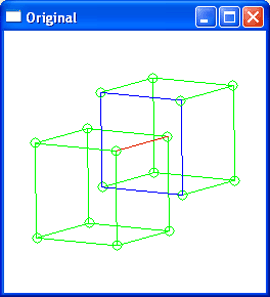 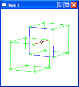
Figure. face:intersect-edge
|
[Top]
face:remove
- Action
-
Removes a face from a body.
-
Filename
-
scm/scmext/bool/rfac_scm.cpp
-
APIs
-
api_remove_face
-
Syntax
-
(face:remove face)
-
Arg Types
-
-
Returns
-
body
Description
This removes the face from its owning body. When edges and vertices are no
longer needed to support faces, they are also removed. This differs from
face:uncover.
- Arguments
-
face
is an input face.
[Top]
face:split
- Action
-
Splits a face along u or v at a given value.
-
Filename
-
scm/scmext/bool/rfac_scm.cpp
-
APIs
-
api_split_face
-
Syntax
-
(face:split face split-along-u use-percent param-value [acis-opts])
-
Arg Types
-
-
Returns
-
boolean
Description
This extension splits a face along a constant u or v parameter
line specified by the supplied arguments. Set split-along-u to #t for a
constant u parameter line, #f for a constant v parameter line. If use-percent
is #t, the split occurs at a relative portion of the parameter range of the
surface of the face between 0 and 1, specified by the argument split-value
(for example, 0.5 splits a face at the midpoint of the parameter range). In
cases where the parameter range is not bounded (for example, when the surface
is a plane), the split occurs at a relative portion of the parameter box of the
face. If use-percent is #f, the split occurs at the explicit parameter
line specified by the argument split-value.
- Arguments
-
face
is an input face.
-
split-along-u
controls whether to split along u or v.
-
use-percent
controls whether the split value is proportional or explicit.
-
split-value
is the split parameter, either proportional or explicit, depending on the
values of the previous arguments.
-
acis-opts
contains parameters for versioning and journaling.
[Top]
face:split-at-disc
- Action
-
Splits a face along G1 or G2 discontinuities.
-
Filename
-
scm/scmext/bool/rfac_scm.cpp
-
APIs
-
api_split_face_at_disc
-
Syntax
-
(face:split-at-disc face [disc-order = 1] [acis-opts])
-
Arg Types
-
-
Returns
-
(face
...)
-
Errors
-
face does not contain discontinuity information
Description
This extension splits a face along the u or v isoparametric lines
at G1 or G2 discontinuity parameters. The list of new faces is returned.
If the edges of the face being split have discontinuities of order 1 or 2, then
a split of the edges is recommended before the split of the face is performed.
Otherwise a correct outcome of the face split cannot be guaranteed.
- Arguments
-
face
is an input face.
-
disc-order
indicates the order of the discontinuities at which to split.
-
acis-opts
contains parameters for versioning and journaling. -
Limitations
-
If the supplied face is an independent face (i.e. no body, lump or shell), it
will return a list of faces which share edges but do not belong to a shell,
lump or body. Also, it will only split at discontinuities in the range of the
face, rather than the underlying surface.
(part:clear)
; create a curve discontinuous in G1 by creating a
; spline with duplicate knots in the interior
(define ctrlpts_pos (list (position -2 0 0)(position -1.5 0 0)
(position 0 0 0)(position .75 0.5 0)
(position 1 0.5 0)(position 1.1 1 0)
(position 1.2 1 0)(position 1.5 1 0)
(position 1.9 .75 0)(position 2 0.5 0)
(position 2.1 .25 0)(position 2.5 0 0)
(position 3 0 0)(position 4 0 0)) )
;; ctrlpts_pos
(define knot_v (list 0 0 0 1 2 3 4 4 4 5 6 7 7 7 8 9 9 9) )
;; knot_v
(define spline (edge:spline-from-ctrlpts ctrlpts_pos knot_v) )
;; spline
(define spline (sweep:law spline (gvector 0 0 2) ))
;; spline
(define f (list-ref (entity:faces spline)0))
;; f
(entity:check f)
;; checked:
;; 0 lumps
;; 0 shells
;; 0 wires
;; 1 faces
;; 1 loops
;; 4 coedges
;; 4 edges
;; 4 vertices
;;()
(define splitfas (face:split-at-disc f))
;; splitfas
(entity:check spline)
;; checked:
;; 1 lumps
;; 1 shells
;; 0 wires
;; 3 faces
;; 3 loops
;; 12 coedges
;; 10 edges
;; 8 vertices
;;()
|
[Top]
face:uncover
- Action
-
Removes the surface of a face, leaving its edges.
-
Filename
-
scm/scmext/bool/rfac_scm.cpp
-
APIs
-
api_uncover_face
-
Syntax
-
(face:uncover face [acis-opts])
-
Arg Types
-
-
Returns
-
body
Description
This extension removes a surface of a face leaving its supporting edges and
vertices. This results in a partly covered body. The return body is the owner
of the input face.
The input face is removed by deleting it and its surface, any associated loops,
and any associated coedges. It leaves the face's edges. If removing a coedge
leaves the edge with no coedges, it is kept. In addition, its immediate owner
is changed either to the shell or to one of the wires in the newly created
wireframe. This differs from the face:unhook,
which removes the face's edges.
- Arguments
-
face
is an input face.
-
acis-opts
contains parameters for versioning and journaling.
; face:uncover
; Create a solid block.
(define block1
(solid:block (position -30 -15 -45)
(position 20 5 40)))
;; block1
; List the current faces of block1.
(entity:faces block1)
;; (#[entity 3 1] #[entity 4 1] #[entity 5 1]
;; #[entity 6 1] #[entity 7 1] #[entity 8 1])
; Create a list of faces from the block.
(define faces (entity:faces block1))
;; faces
; Uncover one of the faces.
(face:uncover (list-ref faces 5))
;; #[entity 2 1]
; Verify a face has been removed by listing current
; faces.
(entity:faces block1)
;; (#[entity 3 1] #[entity 4 1] #[entity 5 1]
;; #[entity 6 1] #[entity 7 1]) |
[Top]
face:unhook
- Action
-
Removes a face from a body.
-
Filename
-
scm/scmext/bool/rfac_scm.cpp
-
APIs
-
api_unhook_face,
api_unhook_faces,
api_combine_body
-
Syntax
-
(face:unhook face [copy] [acis-opts])
-
Arg Types
-
-
Returns
-
body
Description
This Scheme extension removes a face from its owning body and puts a copy into
a new body. When edges and vertices are no longer needed to support faces, they
are also removed. The return body is the owner of the input face.
This differs from the face:uncover.
face:unhook makes a copy of the face. It removes the face, its
surface, its associated loops, its associated coedges, and the associated edges
and vertices no longer needed to support the remaining faces. face:uncover
leaves the face's edges.
The copy argument determines whether unhooked faces are to be produced.
If the copy flag is set to TRUE, api_unhook_faces produces a
copy of the unhooked faces and returns the original body unmodified. If the copy
flag is set to FALSE, then no unhooked bodies are produced. api_combine_body
produces a single body from the resulting unhooked bodies. Thus, api_combine_body
returns a single entity instead of a list of entities.
- Arguments
-
face
is an input.
-
copy
determines whether unhooked faces are to be produced.
-
acis-opts
contains parameters for versioning and journaling.
[Top]
glue:options
- Action
-
Creates or sets the options in the data structure to be used by glue
operations.
-
Filename
-
scm/scmext/bool/glue_scm.cpp
-
APIs
-
None
-
Syntax
-
(glue:options option_1 value_1 ... option_n value_n [glue-opts])
-
Arg Types
-
-
Returns
-
glue-options
Description
Every option default value is set to #f (unset). These options are designed to
provide additional information to the glue operation for improved performance.
The information provided must be accurate because the glue operation relies
heavily on this information.
See bool:glue-unite for the definition of
coincident faces.
Given bodies b1 and b2, a coincident patch P1 in b1 is a maximal set of
connected faces of b1 such that there exists a corresponding maximal set P2 of
connected faces in b2 and a (well-defined onto) coincidence mapping from P1 to
P2.
Face f1 covers face f2 if the point set of f2 is a subset of the point set of
f1. Patch P1 covers patch P2 if the point set of P2 is a subset of the point
set of P1. Given a pair of coincident patches P1 and P2, P1 is a strict cover
of P2 if the point set of P2 is a subset of the interior point set of P1.
The
option_i
argument can take one of the following values:
"patch_and_face_cover"
"blank_patches_strict_cover"
"single_face_patch"
"non_trivial"
Setting "patch_and_face_cover" to #t will induce a performance enhancement.
"patch_and_face_cover" may be set to #t if the following conditions are
satisfied:
for every pair of coincident faces (to be specified in the
glue operation), one face covers the other face;
for every pair of coincident patches, one patch covers the
other patch.
In addition to setting "patch_and_face_cover" to #t, setting
"blank_patches_strict_cover" to #t will induce another performance enhancement.
"blank_patches_strict_cover" may be set to #t if the following conditions are
satisfied:
"patch_and_face_cover" is set to #t;
every patch in the blank (first) body is a strict cover of
its corresponding patch in the tool (second) body.
In addition to setting "patch_and_face_cover" to #t, setting "single_face_patch"
to #t will induce another performance enhancement. "single_face_patch" may be
set to #t if the following conditions are met:
"patch_and_face_cover" is set to #t;
every patch consists of precisely one face;
for each patch, all edges are coincident and all vertices are
coincident. In other words, the corresponding pair of coincident faces are
geometrically and topologically identical.
Thus "blank_patches_strict_cover" and "single_face_patch" cannot both be set to
#t.
"non_trivial" may be set to #t if it is guaranteed that the Boolean operation
will be non-trivial. In the case of glue-unite, this is when the tool body lies
outside the blank body. In the case of glue-subtract, this is when the tool
body is completely contained in the blank body. This will induce another
performance enhancement. It is not dependent on the previous flags.
- Arguments
-
option_i
can take the following values: "patch_and_face_cover",
"blank_patches_strict_cover", "single_face_patch", "non_trivial".
-
value_i
is the boolean value of option_i.
-
glue-opts
is the pre-existing
glue-options object to set. If none is supplied, a new
glue-options object is created.
[Top]
solid:check-ff-intersections
- Action
-
Obsolete: Use solid:check-ff-ints instead.
Checks all faces for improper intersections. -
Filename
-
scm/scmext/bool/bool_scm.cpp
-
APIs
-
api_check_entity_ff_ints
-
Syntax
-
(solid:check-ff-intersections entity [file-name][acis-opts])
-
Arg Types
-
-
Returns
-
entity
| entity
...
Description
This extension checks all faces for improper intersections.
- Arguments
-
entity
is an input entity.
-
file-name
is the name of the file.
-
acis-opts
contains parameters for versioning and journaling.
; solid:check-ff-intersections
; Define a solid block
(define b (solid:block (position 0 0 0)
(position 20 20 20)))
;; b
(solid:check-ff-intersections b)
;; () |
[Top]
solid:check-ff-ints
- Action
-
Checks a solid body for improper face intersections.
-
Filename
-
scm/scmext/bool/ffint_scm.cpp
-
APIs
-
api_check_entity_ff_ints
-
Syntax
-
(solid:check-ff-ints body [chk-lumps-and-shells=#f] [make-wire-body=#t]
[acis-opts])
-
Arg Types
-
-
Returns
-
(pair
pair
... [entity
...] [entity])
Description
This extension checks all faces of a solid body for improper intersections. The
improper intersections are returned as a list of pairs of faces or edges. If chk-lumps-and-shells
is set to #t, then improper lump and shell containments are also reported. By
default, a wire body representing the improper intersections, colored white for
visual purposes, is returned, but this may be disabled by setting make-wire-body
to #f.
Note: It is recommended that a full check on the body using
entity:check at level 70 is performed before calling this
extension, since there may be other invalidities in the body. If improper
intersections are reported by
entity:check, then this extension may be used to return the
actual pairs of faces or edges that intersect improperly.
- Arguments
-
body
is an input body.
-
chk-lumps-and-shells
controls whether improper lump and shell containments should be reported.
-
make-wire-body
controls whether a wire body representing the improper intersections should be
returned.
-
acis-opts
contains parameters for versioning and journaling.
; solid:check-ff-ints
; Define two overlapping solid blocks
(define b1 (solid:block (position 0 0 0)
(position 20 20 20)))
;; b1
(define b2 (solid:block (position 10 10 10)
(position 30 30 30)))
;; b2
; Combine the blocks to create an invalid body
(define combine (body:combine (list b1 b2)))
;; combine
; Check for improper intersections
(solid:check-ff-ints b1)
;; entid 527aa28 & 5274818: Error: improper face intersection
;; entid 527aa28 & 5274300: Error: improper face intersection
;; entid 527a568 & 5275b18: Error: improper face intersection
;; entid 527a568 & 5274300: Error: improper face intersection
;; entid 527a0a8 & 5275b18: Error: improper face intersection
;; entid 527a0a8 & 5274818: Error: improper face intersection
;; Body containing improper intersections created.
;; ((#[entity 4 1] . #[entity 3 1]) (#[entity 4 1] . #[entity 5 1])
;; (#[entity 7 1] . #[entity 6 1]) (#[entity 7 1] . #[entity 5 1])
;; (#[entity 8 1] . #[entity 6 1]) (#[entity 8 1] . #[entity 3 1]) #[entity 9
1])
|
[Top]
solid:check-list-ff-intersections
- Action
-
Checks selected faces in an entity for improper intersections.
-
Filename
-
scm/scmext/bool/bool_scm.cpp
-
APIs
-
api_check_list_ff_ints
-
Syntax
-
(solid:check-list-ff-intersections face_list1 [file-name][face-list2]
[acis-opts])
-
Arg Types
-
-
Returns
-
entity
| entity
...
Description
This extension is a specialized version of solid:check-ff-ints, as it checks
only selected faces of an entity for improper intersections. Pairs of faces are
intersected where one face belongs to face_list1 and another to face_list2.
- Arguments
-
face_list1
is the first list of faces.
-
file-name
is the name of the file.
-
-
face_list2 is the second list of faces.
-
acis-opts
contains parameters for versioning and journaling.
; solid:check-list-ff-intersections
(part:clear)

; Define two overlapping solid blocks
(define b1
     (solid:block (position 0 0 0) (position 20 20 20)))
;; b1
(define b2
    (solid:block (position 10 10 10) (position 30 30 30)))
;; b2

; Combine the blocks to create an invalid body
(define combine (body:combine (list b1 b2)))
;; combine

;pick a face
(define f1 (pick:face (ray (position 5 5 5) (gvector 0 0 1))))
;;f1
;pick a face
(define f2 (pick:face (ray (position 5 5 5) (gvector 1 0 0))))
;;f2

;add picked faces to the first list
(define f_list1 (list f1 f2))
;;f_list1

;pick a face
(define f3 (pick:face (ray (position 25 25 25) (gvector 0 -1 0))))
;;f3

;add picked face to the second list
(define f_list2 (list f3))

;check for improper intersections for the given list of faces
(solid:check-list-ff-intersections f_list1 f_list2 )
;;(#[entity 6 1] #[entity 7 1])
|
[Top]
solid:imprint
- Action
-
Imprints curves of intersection of two bodies onto the faces of bodies.
-
Filename
-
scm/scmext/bool/bool_scm.cpp
-
APIs
-
api_imprint
-
Syntax
-
(solid:imprint body1 body2 [acis-opts])
-
Arg Types
-
-
Returns
-
boolean
Description
Calculates the curves of intersection of the two bodies and imprints these
curves onto the faces of the two bodies. This results in the original faces
being split either by breaking the face into several pieces or by adding slits
to the face.
If no intersections exist between the bodies, a "no intersection" message
occurs.
- Arguments
-
body1
is one of the input bodies.
-
body2
is the other input body.
-
acis-opts
contains parameters for versioning and journaling.
[Top]
solid:imprint-stitch
- Action
-
Joins
body1
and
body2
along the intersection graph.
-
Filename
-
scm/scmext/bool/bool_scm.cpp
-
APIs
-
api_imprint_stitch
-
Syntax
-
(solid:imprint-stitch body1 body2 [acis-opts])
-
Arg Types
-
-
Returns
-
body
Description
Joins
body1
and
body2
along edges or vertices of the intersection curve between the body's faces.
Like solid:stitch, solid:imprint-stitch
performs a local union operation when creating a nonmanifold edge and may
change face sidedness and containment. Bodies with no face-face intersections
will be grouped in the output body (body1)
regardless.
body2
is deleted.
- Arguments
-
body1
is one of the input bodies.
-
body2
is the other input body.
-
acis-opts
contains parameters for versioning and journaling.
[Top]
solid:imprint-shadow-edges
- Action
-
Computes and imprints silhouette edges that are tangent to shadow casted by
draft.
-
Filename
-
scm/scmext/bool/bool_scm.cpp
-
APIs
-
api_imprint_shadow_edges
-
Syntax
-
(solid:imprint-shadow-edges facelist pulldirection angle imprint [acis-opts])
-
Arg Types
-
-
Returns
-
A list of silhouette-edges, that may or many not belong to the owner of the
faces.
-
Description
-
This extension creates and imprints shadow edges in given faces. The silhouette
is defined by a tangencial field, between the surface, the direction of the
draft and the given angle. Some surfaces can have more than one silhouette;
others, like planes, have none. This function is inspired by shadow taper.
-
Limitations
-
Planar surfaces do not have silhouettes.
-
- Arguments
-
facelist is the entity list.
-
pulldirection is the unit vector.
-
angle specifies the angle in degrees.
-
imprint specifies whether shadow edges are to be imprinted (#t).
-
acis-opts contains parameters for versioning and journaling.
(part:clear)
;; #t
(define s (solid:cylinder (position 0 0 0)(position  0 0 3) 1))
;; s
(solid:blend-edges (list-ref (entity:edges s) 1) 0.25)
(define s2 (solid:cylinder (position 3 0 0)(position  3 0 3) 1))
;; s2
(solid:blend-edges (list-ref (entity:edges s2) 1) 0.25)
(view:dl)
(front)
(zoom-all)
(define f (car (entity:faces s)))
;; f
(define sils (solid:imprint-shadow-edges f (gvector 0 0 1) 45 #t))
;; sils
(entity:set-color sils 1)
(define f2 (car (entity:faces s2)))
;; f2
;; Note the difference in the angle, caused by the draft direction
(define sil2 (solid:imprint-shadow-edges f2 (gvector 1 0 2) 45 #t))
;; sil2
(entity:set-color sil2 1)
|
[Top]
solid:inter-graph
- Action
-
Computes the intersection graph between two bodies and returns it as a
specialized wire body.
-
Filename
-
scm/scmext/bool/bool_scm.cpp
-
APIs
-
api_bool_make_intersection_graph
-
Syntax
-
(solid:inter-graph blank tool [acis-opts])
-
Arg Types
-
-
Returns
-
wire-body
Description
Computes the intersection graph (or slice) between two bodies and returns it as
a specialized wire body with Boolean attributes and extra coedges. If no
intersections exist between the bodies, a no intersection message occurs.
- Arguments
-
blank
is the body to be sliced.
-
tool
is the slicing body.
-
acis-opts
contains parameters for versioning and journaling. -
Limitations
-
The intersection graph is not a valid body. It represents the specialized wire
that is ready to be imprinted. This Scheme extension is purely designed for
debugging purposes and the result is not intended for modeling operations. See
solid:slice to get a wire body suitable for general modeling.
; solid:slice
; Create a solid block.
(define block1 (solid:block (position -20 -20 -20)
(position 20 20 20)))
;; block1
; Set color for block1
(entity:set-color block1 2)
;; ()
; Create another solid block
(define block2 (solid:block (position -30 -30 -30)
(position 10 10 10)))
;; block2
; Set color for block2
(entity:set-color block2 3)
;; ()
; Slice the two blocks
(define slice (solid:inter-graph block1 block2))
;; slice
; OUTPUT Original Sliced Blocks
; Remove the blocks to see the slice.
(entity:delete (list block1 block2))
;; ()
; OUTPUT Resulting Slice |
[Top]
solid:intersect
- Action
-
Intersects two or more solids.
-
Filename
-
scm/scmext/bool/bool_scm.cpp
-
APIs
-
api_intersect
-
Syntax
-
(solid:intersect body1 body2 [... bodyn] [acis-opts])
-
Arg Types
-
-
Returns
-
entity
Description
This extension requires that a minimum of two solid bodies be specified. The
result is returned in the form of a modified body1 and all other bodies
are deleted.
- Arguments
-
body1, ... , bodyn
are input bodies.
-
acis-opts
contains parameters for versioning and journaling.
[Top]
solid:planar-slice
- Action
-
Slices a solid body with a plane to produce a wire body.
-
Filename
-
scm/scmext/bool/bool_scm.cpp
-
APIs
-
api_planar_slice
-
Syntax
-
(solid:planar-slice body plane-position plane-normal [acis-opts])
-
Arg Types
-
-
Returns
-
wire-body
-
Arguments
-
body
is a solid body entity.
-
plane-position
specifies the location to slice.
-
plane-normal
specifies the direction to slice.
-
acis-opts
contains parameters for versioning and journaling.
[Top]
solid:slice
- Action
-
Computes the intersection graph between two bodies and returns it as a wire
body suitable for general use.
-
Filename
-
scm/scmext/bool/bool_scm.cpp
-
APIs
-
api_slice
-
Syntax
-
(solid:slice blank tool [bool-opts] [acis-opts])
-
Arg Types
-
-
Returns
-
wire-body
-
Description
-
Computes the intersection graph (or slice) between two bodies. If no
intersections exist between the bodies, a no intersection message occurs. Since
the intersection graph is a specialized wire body with Boolean attributes and
extra coedges (see solid:inter-graph),
these are removed to return a wire body suitable for general use.
-
Arguments
-
blank
is the body to be sliced.
-
tool
is the slicing body.
-
bool-opts
specifies Boolean options. Refer to
Bool_Options for more details.
-
acis-opts
contains parameters for versioning and journaling.
[Top]
solid:split
- Action
-
Splits all periodic faces of a body along the seams.
-
Filename
-
scm/scmext/bool/bool_scm.cpp
-
APIs
-
api_split_periodic_faces
-
Syntax
-
(solid:split body [acis-opts])
-
Arg Types
-
-
Returns
-
body
Description
This command ensures that a body is well formed by splitting all periodic faces
of the body along u, v, or both. The periodic faces of the body are
split at the lower parameter limit, and halfway between the lower and upper
parameter limit. Analytic surfaces are handled, but periodic spline surfaces
are not.
- Arguments
-
body
is the input body.
-
acis-opts
contains parameters for versioning and journaling.
[Top]
solid:stitch
- Action
-
Joins two bodies (faces) along edges or vertices of identical geometry.
-
Filename
-
scm/scmext/bool/bool_scm.cpp
-
APIs
-
api_stitch
-
Syntax
-
(solid:stitch body1 body2 [split] [acis-opts])
-
Arg Types
-
-
Returns
-
body
Description
Joins two face bodies,
body1
and
body2, along edges or vertices that are
identical. Stitching only operates on faces, not on wires, and only stitches
faces to faces. No faces are deleted in order to complete the stitch function.
If wires exist in one of the bodies being stitched, but do not participate in
the stitch (i.e., they do not coincide with edges in the other body), they will
transfer to the resulting body.
The argument
body1
is returned as the resulting body.
body2, is deleted unless it is the same
as
body1. For example, a body might need
internal stitching. One can stitch
body1
to itself. In such a case
body1
is not deleted.
If the
split
option is not specified, the edges must be identical along their entire length,
otherwise stitch splits edges along identical edge subregions. Single-sided
faces that are stitched together to form a two-manifold edge must have
compatible orientations. This is not required for double-sided faces.
Unlike extensions such as solid:unite,
solid:stitch is not a Boolean operation. Stitching is simpler than a
Boolean because it avoids face-face intersections and the evaluation of lump
and shell containments.
- Arguments
-
body1
and
body2
are input bodies which needs to be united along edges or vertices.
-
split
is an option to specify whether the edges are identical along their entire
length.
-
acis-opts
contains parameters for versioning and journaling.
; solid:stitch
; Create a solid block.
(define block1
(solid:block (position -20 -20 -20)
(position 20 20 20)))
;; block1
; Create a list of faces from the block.
(define faces (entity:faces block1))
;; faces
; Uncover a face.
(define uncover (face:uncover (list-ref faces 5)))
;; uncover
; Copy the open block.
(define block2
(entity:copy block1))
;; block2
; Flip and position the block to match open faces.
(define transform1 (entity:transform block2
(transform:rotation
(position 0 0 0) (gvector 0 0 1) 180)))
;; transform1
(define transform2 (entity:transform block2
(transform:translation
(gvector 40 0 0))))
;; transform2
; Join block1 and block2 to form one lump. (Note:
; you can run (entity:check stitch) to check results.
(define stitch (solid:stitch block1 block2))
;; stitch |
[Top]
solid:subtract
- Action
-
Subtracts a list of solids from a solid.
-
Filename
-
scm/scmext/bool/bool_scm.cpp
-
APIs
-
api_subtract
-
Syntax
-
(solid:subtract body-1 body-2 [...body-n] [acis-opts])
-
Arg Types
-
-
Returns
-
body
Description
Subtracts a list of solids from a solid. All bodies must refer to solid bodies.
body-2
through
body-n
are subtracted from body-1. This extension returns the name of
body-1
and deletes
body-2
through
body-n.
- Arguments
-
body-1,
body-2,
body-n
are input bodies.
-
acis-opts
contains parameters for versioning and journaling.
[Top]
solid:unhook-wire-edge
- Action
-
Unhooks an edge belonging to a wire from a body and returns a new wire-body.
-
Filename
-
scm/scmext/bool/bool_scm.cpp
-
APIs
-
api_unhook_wire_edge
-
Syntax
-
(solid:unhook-wire-edge edge [acis-opts])
-
Arg Types
-
-
Returns
-
body
Description
This extension unhooks an edge belonging to a wire from a body and returns a
new wire-body.
- Arguments
-
edge
is an input edge belonging to a wire from a body.
-
acis-opts
contains parameters for versioning and journaling.
; solid:unhook-wire-edge
; Define a wire
(define wire (wire-body:points (list (position 0 0 0)
(position 40 0 0) (position 40 40 0)
(position 40 40 40))))
;; wire
; wire has 3 edges
(entity:check wire)
;; checked:
;; 1 lumps
;; 1 shells
;; 1 wires
;; 0 faces
;; 0 loops
;; 3 coedges
;; 3 edges
;; 4 vertices
;; ()
(define edge0 (car (entity:edges wire)))
;; edge0
; unhook the edge
(define new_wire (solid:unhook-wire-edge edge0))
;; new_wire
; new_wire has 1 edge
(entity:check new_wire)
;; checked:
;; 1 lumps
;; 1 shells
;; 1 wires
;; 0 faces
;; 0 loops
;; 1 coedges
;; 1 edges
;; 2 vertices
;; ()
; original wire has 2 edges
(entity:check wire)
;; checked:
;; 1 lumps
;; 1 shells
;; 1 wires
;; 0 faces
;; 0 loops
;; 2 coedges
;; 2 edges
;; 3 vertices
;; () |
[Top]
solid:unite
- Action
-
Unites two or more solids.
-
Filename
-
scm/scmext/bool/bool_scm.cpp
-
APIs
-
api_unite
-
Syntax
-
(solid:unite body1 body2 [...bodyn] [acis-opts])
-
Arg Types
-
-
Returns
-
body
Description
Unites two or more solid bodies. The result is returned in the form of a
modified body1 and all other bodies are deleted.
- Arguments
-
body1,...
bodyn
are input bodies.
-
acis-opts
contains parameters for versioning and journaling.
[Top]
solid:unstitch-nm
- Action
-
Decomposes the input body along nonmanifold edges and vertices.
-
Filename
-
scm/scmext/bool/bool_scm.cpp
-
APIs
-
api_unstitch_nonmani
-
Syntax
-
(solid:unstitch-nm body [acis-opts])
-
Arg Types
-
-
Returns
-
(body
...)
Description
Decomposes the input body along nonmanifold edges and vertices, duplicating
edges and vertices and making each decomposed region a separate lump in the
output body. All lumps in the body become manifold unless they had
self-nonmanifold edges. The command also inserts all groups of wire edges into
the body's wire list if they were not already there. Returned list of bodies
contains original body separated into 3d bodies, sheet bodies, laminar bodies,
and wire bodies, as present. Refer to
api_unstitch_nonmani for additional information.
Note: The bodies returned in the decomposition list may not be suitable
for modeling operations, since duplicate edges and vertices may be present. Use
body:separate to create disjoint bodies.
- Arguments
-
body
is the input body.
-
acis-opts
contains parameters for versioning and journaling.
[Top]
tolerant:detect-short-edges
-
Action
Detects all edges from a
solid or wire body that are shorter in length than the specified tolerance. -
Filename
-
scm/scmext/bool/sliver_scm.cpp
-
APIs
-
api_detect_short_edges
-
Syntax
-
(tolerance:detect-short-edges entity [tolerance=SPAresfit]
[replace=#f])
-
Arg Types
-
-
Returns
-
(entity
...)
Description
This extension detects all edges of the supplied entity that are shorter than
the specified tolerance, and replaces them with tolerant vertices if replace
is set to #t. If replace is set to #f, the list of short edges is
returned and no short edges are replaced. Otherwise, the list of replacement
tolerant vertices is returned.
- Arguments
-
entity
is the input entity.
-
tolerance
is the specified tolerance for detecting short edges.
-
replace
controls whether short edges should be automatically replaced with tolerant
vertices, if detected.
; tolerant:detect-short-edges
; Define a simple skin that results in a
; short edge being created
(define edge1 (wire-body (list
(edge:linear (position 0 0 0)
(position 1 0 0)))))
;; edge1
(define edge2 (wire-body (list (edge:linear
(position 0.5 1 0) (position 0.500001 1 0)))))
;; edge2
(define skin_ops (skin:options "arc_length"
#f "no_twist" #t "align" #t "solid" #f))
;; skin_ops
(define skin (sheet:skin-wires
(list edge1 edge2) skin_ops))
;; skin
; Check the body before the short edge replacement
(entity:check skin)
; checked:
; 1 lumps
; 1 shells
; 0 wires
; 1 faces
; 1 loops
; 4 coedges
; 4 edges
; 4 vertices
;; ()
; Detect the short edge
(define short_edges
(tolerant:detect-short-edges skin #f))
;; short_edges
(edge:length (car short_edges))
;; 1.00000000002876e-006
; Replace the short edge
(define replace_edges
(tolerant:detect-short-edges skin #t))
;; replace_edges
(define v (car replace_edges))
;; v
(entity:debug v)
;; "tvertex"
; Validate the remaining body
(entity:check skin)
; 1 lumps
; 1 shells
; 0 wires
; 1 faces
; 1 loops
; 3 coedges
; 3 edges
; 3 vertices
;; ()
(define tol_report (tolerant:report skin))
; Vertex tolerance = 4.472138e-007
; No tolerant edges
;; tol_report |
[Top]
tolerant:detect-sliver-faces
-
Action
Returns all sliver faces
from a body whose maximum distance among the edges is smaller than the given
tolerance. -
Filename
-
scm/scmext/bool/sliver_scm.cpp
-
APIs
-
api_detect_sliver_faces
-
Syntax
-
(tolerant:detect-sliver-faces entity [tolerance] [replace=#f])
-
Arg Types
-
-
Returns
-
(entity
...)
Description
This extension returns all sliver faces from the supplied entity whose maximum
distance among the edges is smaller than the specified tolerance. If no
tolerance is specified, the lesser of (10*resfit) and (minimum side of the
entity's bounding box divided by 1250) is used by default. If the third
argument replace is set to #t, the detected removable sliver faces will
be automatically replaced with tolerant edges.
When the option replace is set to #t, first, this extension detects all
the short edges and replaces them with tolerant vertices. Next, it attempts to
detect all the two-edge or three-edge sliver faces and replace them with
tolerant edges. The list of tolerant edges is then returned.
Note: The Scheme extension tolerant:replace-face-with-tedge
does not attempt to replace the short edges with tolerant vertices. Therefore,
to successfully remove the sliver faces detected by this extension, use the
option replace and not the Scheme extension tolerant:replace-face-with-tedge.
- Arguments
-
entity
is the input entity.
-
tolerance
is the specified tolerance for an input entity.
-
replace
is an optional argument that specifies short edges should be automatically
replaced, if detected.
; tolerant:detect-sliver-faces
(part:clear)
;; ()
; Create two adjacent blocks
(define b1 (solid:block (position 0 0 0)
(position 20 20 20)))
;; b1
(define b2 (solid:block (position 20 0 0)
(position 40 20 20)))
;; b2
; Rotate one block by a tiny amount and subtract
(define rotate (entity:rotate b2 20 0 0 0 0 1 0.05))
;; rotate
(define subtract (bool:subtract b1 b2))
;; subtract
(entity:check b1)
;; checked:
;; 1 lumps
;; 1 shells
;; 0 wires
;; 7 faces
;; 7 loops
;; 30 coedges
;; 15 edges
;; 10 vertices
;; ()
; Identify the sliver faces
(define sliver-faces (tolerant:detect-sliver-faces b1))
;; sliver-faces
(length sliver-faces)
;; 1
; Remove the sliver face and replace with a tolerant edge
(define replace (tolerant:detect-sliver-faces b1 #t))
;; replace
(entity:check b1)
;; checked:
;; 1 lumps
;; 1 shells
;; 0 wires
;; 6 faces
;; 6 loops
;; 24 coedges
;; 12 edges
;; 8 vertices
;; ()
(define tol-report (tolerant:report b1))
;; Vertex tolerance = 4.363323e-003
;; Edge tolerance = 7.615435e-006
;; tol-report
|
[Top]
tolerant:replace-edge-with-tvertex
- Action
-
Replaces a list of edges with tolerant vertices.
-
Filename
-
scm/scmext/bool/sliver_scm.cpp
-
APIs
-
api_replace_edge_with_tvertex
-
Syntax
-
(tolerant:replace-edge-with-tvertex edge-list [ao])
-
Arg Types
-
-
Returns
-
(entity
...)
Description
The argument
edge-list
specifies a list of edges that will be converted to tolerant vertices.
The extension returns a list of tolerant vertices that were created during the
replacement. This extension does not take edge lengths into consideration. It
simply replaces all edges specified unless the edges are in a closed loop. If
the edges are closed, replacement is not performed. To specifically replace
short edges, the extension tolerant:detect-short-edges
with its replace option set to #t is recommended.
- Arguments
-
edge-list
specifies a list of edges that will be converted to tolerant vertices.
-
ao
contains parameters for versioning and journaling.
; tolerant:replace-edge-with-tvertex
; Define a wire body with an edge to be replaced
(define wire (wire-body
(list (edge:linear (position 0 0 0) (position 3 0 0))
(edge:linear (position 3
0 0) (position 3.1 0 0))
(edge:linear (position
3.1 0 0) (position 5 0 0)))))
;; wire
; Replace the middle edge with a tvertex.
; First use tolerant-detect-short-edges with
; a specified tolerance to detect it.
(define short_edge
(tolerant:detect-short-edges wire 0.2))
;; short_edge
(define replace
(tolerant:replace-edge-with-tvertex short_edge))
;; replace
; Check the resulting body and tvertex
(entity:check wire)
;; checked:
;; 1 lumps
;; 1 shells
;; 1 wires
;; 0 faces
;; 0 loops
;; 2 coedges
;; 2 edges
;; 3 vertices
;; ()
(length (entity:tvertices wire))
;; 1 |
[Top]
tolerant:replace-face-with-tedge
- Action
-
Replaces a two-edge or three-edge face with a tolerant edge.
-
Filename
-
scm/scmext/bool/sliver_scm.cpp
-
APIs
-
api_replace_face_with_tedge
-
Syntax
-
(tolerant:replace-face-with-tedge face)
-
Arg Types
-
-
Returns
-
(entity
...)
Description
This extension replaces a face containing a single loop of two or three edges
with a tolerant edge. The face is removed, an edge of the face is converted
into a tolerant edge, and other subsequent topological manipulations are
performed.
Note: As this Scheme extension is restricted to faces with two or three
edges, the recommended way to replace sliver faces detected by tolerant:detect-sliver-faces
is to use its replace option, and not this Scheme extension.
- Arguments
-
face
is the input face.
; tolerant:replace-face-with-tedge
; Please note that this is an artificial example.
; The same result could be achieved more quickly
; using only tolerant:detect-sliver-faces with
; the replace option set to #t
(part:clear)
;; ()
; Create a block and imprint 4 sliver faces
(define b1 (solid:block (position 0 0 0)
(position 20 20 20)))
;; b1
(define sheet
(sheet:2d
(sheet:face
(face:plane (position
0.000002 -10 30) 40 40 (gvector 1 0 0)))))
;; b2
(define imprint (solid:imprint b1 sheet))
;; imprint
(entity:delete sheet)
;; ()
; Replace the short edges with tolerant vertices
(define tol-verts (tolerant:detect-short-edges b1 #t))
;; tol-verts
; We now have 4 two-edge faces
(define sliver-faces (tolerant:detect-sliver-faces b1))
;; sliver-faces
(define fn-num-edges (lambda (f) (length (entity:edges f))))
;; fn-num-edges
(map fn-num-edges sliver-faces)
;; (2 2 2 2)
; Since each sliver face has two edges, we can replace them
; using tolerant:replace-face-with-tedge
(define tedges (map tolerant:replace-face-with-tedge sliver-faces))
;; tedges
(entity:check b1)
;; checked:
;; 1 lumps
;; 1 shells
;; 0 wires
;; 6 faces
;; 6 loops
;; 24 coedges
;; 12 edges
;; 8 vertices
;; ()
(define tol-report (tolerant:report b1))
;; Vertex tolerance = 1.000000e-006
;; Edge tolerance = 0.000000e+000
;; tol-report
|
[Top]
wire:clean
-
Action
Removes the attributes
and extra coedges present on a wire body generated by the section or slice
operation. -
Filename
-
scm/scmext/bool/bool_scm.cpp
-
APIs
-
api_clean_wire
-
Syntax
-
(wire:clean wire [acis-opts])
-
Arg Types
-
-
Returns
-
wire-body
Description
This extension removes the attributes and extra coedges present on a wire body
generated by the section or slice operation. The optional
acis-opts
contains parameters for versioning and journaling.
- Arguments
-
wire
is the input wire body.
-
acis-opts
contains parameters for versioning and journaling.
; wire:clean
; Define a solid sphere
(define b1 (solid:sphere (position 0 0 0) 1))
;; b1
; Define a solid block
(define b2 (solid:block (position 0 0 0) (position 1 1 1)))
;; b2
; compute the slice keeping all attributes
(define sli1 (solid:inter-graph b1 b2))
;; sli1
; check that we have the attributes
(entity:debug sli1 3)
;; 1 body record, 40 bytes
;; 21 attrib records, 1460 bytes
;; 1 wire record, 48 bytes
;; 1 transform record, 144 bytes
;; 12 coedge records, 672 bytes
;; 3 edge records, 240 bytes
;; 3 vertex records, 108 bytes
;; 3 curve records, 672 bytes
;; 3 point records, 216 bytes
;; Total storage 3600 bytes
;; wire body
(wire:clean sli1)
;; #[entity 3 1]
; check that only display_attribute and id_attribute remain
(entity:debug sli1 3)
;; 1 body record, 40 bytes
;; 2 attrib records, 108 bytes
;; 1 wire record, 48 bytes
;; 1 transform record, 144 bytes
;; 3 coedge records, 168 bytes
;; 3 edge records, 240 bytes
;; 3 vertex records, 108 bytes
;; 3 curve records, 672 bytes
;; 3 point records, 216 bytes
;; Total storage 1744 bytes
;; wire body |
[Top]
© 1989-2007 Spatial Corp., a Dassault Systèmes company. All
rights reserved.
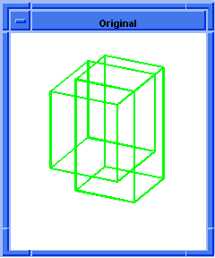
![]()

