Creating Surfaces
ACIS contains many standard surface types that can be created quickly, and if desired, already as face topological elements. These include planar faces, cylindrical faces, conical faces, spherical faces, torus faces, spline faces, and faces using law mathematical functions.
ACIS also provides techniques for creating more freeform surfaces. These techniques include covering, skinning, lofting, and net surfaces, all of which create a surface from a wireframe or edges.
- Covering
- Requires that the edges be a closed loop over which a surface is fit.
- Skinning
- Passes a surface through a disjoint set of edges.
- Lofting
- Starts with a surface and extends this surface to pass through a disjoint set of edges.
- Net surfaces
- Stretches a surface across a set of bidirectional curves.
Of these techniques, covering is the easiest but least flexible. Aside from requiring a bounding closed loop of edges, covering provides little control over the internal shape of the surface. The initial wire body does not have to be planar. However, in a non-planar case, unique surface characteristics away from the bounding edges cannot be specified.
Net surfaces probably provides the most control over the shape of the resulting surface, but requires more planning in defining the uv curves, in getting the u curves to intersect with or be within a specified tolerance of the v curves, and in selecting an appropriate tolerance for interpolation.
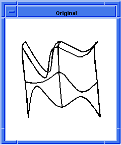
The following example, interpolates a surface through a network of bidirectional curves. The given wires define the cross-sections to be interpolated by the resulting sheet body. There must be at least four wire bodies, two in each direction. The start points of the curves in the v direction must lie on the first curve in the u direction, and vice versa. The end points of the v curves must lie in the last curve in the u direction, and vice versa.
If all of the curves intersect, then the surface passes through the curves and their intersections. If any of the u curves of the network do not intersect all of v curves at some point, the intersection is interpolated. The maximum distance for the interpolation is governed by the tolerance argument. The default for this tolerance value is SPAresfit.
Scheme Example
| ; Establish the correct options for viewing. (option:set "sil" #f) ;; #t (option:set "u_par" 5) ;; -1 (option:set "v_par" 7) ;; -1 ; Create a series of points to use later for splines. (define v1 (list (position 0 0 0) (position 5 10 0) (position 10 5 0) (position 15 15 0) (position 20 0 0))) ;; v1 (define v2 (list (position 0 10 5) (position 5 5 5) (position 10 15 5) (position 15 10 5) (position 20 10 5))) ;; v2 (define v3 (list (position 0 20 10) (position 5 15 10) (position 10 20 10) (position 15 5 10) (position 20 20 10))) ;; v3 (define v4 (list (position 0 15 15) (position 5 10 15) (position 10 15 15) (position 15 0 15) (position 20 15 15))) ;; v4 (define u1 (list (position 0 0 0) (position 0 10 5) (position 0 20 10) (position 0 15 15))) ;; u1 (define u2 (list (position 10 5 0) (position 10 15 5) (position 10 20 10) (position 10 15 15))) ;; u2 (define u3 (list (position 20 0 0) (position 20 10 5) (position 20 20 10) (position 20 15 15))) ;; u3 ; Create a series of spline curve wire-bodies. ; in the u and v direction. (define my_v1 (wire-body (edge:spline v1))) ;; my_v1 (define my_v2 (wire-body (edge:spline v2))) ;; my_v2 (define my_v3 (wire-body (edge:spline v3))) ;; my_v3 (define my_v4 (wire-body (edge:spline v4))) ;; my_v4 (define my_u1 (wire-body (edge:spline u1))) ;; my_u1 (define my_u2 (wire-body (edge:spline u2))) ;; my_u2 (define my_u3 (wire-body (edge:spline u3))) ;; my_u3 ; Create a net surface from the uv curves. (define net1 (sheet:net-wires (list my_v1 my_v2 my_v3 my_v4) (list my_u1 my_u2 my_u3) #t )) ;; net1 ; Save the results to an output file. (part:save "tmpnetsurf1.sat") ;; #t |


Figure. Net Surface
Some of the Scheme extensions related to surfaces are:
- face:cone
-
Creates a conical face relative to the active WCS.
- face:cylinder
- Creates a cylindrical face relative to the active WCS.
- face:intersect
- Gets the intersection curve between two faces.
- face:law
- Creates a new face whose uv parameters are determined by law functions.
- face:offset
- Creates a new face offset from a given face.
- face:plane
- Creates a planar face.
- face:sphere
- Creates a spherical face.
- face:spline-ctrlpts
- Creates a spline face using control points.
- face:spline-grid
- Creates a spline face using a grid.
- face:torus
- Creates a toroidal face.
- section
- Creates a data structure used as input to the sheet:loft-wires extension.
- sheet:cover
- Modifies a sheet body by covering each of its simple loops of external edges by a face.
- sheet:cover-wires
- Creates a sheet body from a wire body.
- sheet:face
- Creates a sheet body from a given face.
- sheet:loft-wires
- Creates a sheet body that interpolates a series of wires.
- sheet:net-wires
- Creates a sheet body that interpolates a series of wires.
- sheet:planar-wire
- Creates a planar sheet body from a planar wire body.
- sheet:skin-wires
- Creates a sheet body that interpolates a series of wires.
[Top]
© 1989-2007 Spatial Corp., a Dassault Systèmes company. All rights reserved.