Scheme Extensions |
|
|
|
Technical Article |
| Scheme is a public domain programming language, based on the LISP language,
that uses an interpreter to run commands. ACIS provides extensions (written
in C++) to the native Scheme language that can be used by an application
to interact with ACIS through its Scheme Interpreter. The C++ source files
for ACIS Scheme extensions are provided with the product. Spatial's Scheme
based demonstration application, Scheme ACIS Interface Driver Extension
(Scheme AIDE), also uses these Scheme extensions and the Scheme Interpreter.
|
body:edge-regions
- Action
-
Repairs coplanar edge vertices within point coincident tolerance to
form regions. Regions are separated into sheet bodies.
Filename-
scm/scmext/covr/wire_heal_scm.cpp
APIs-
api_heal_edges_to_regions
Syntax-
(body:edge-regions edge-list [coin-tol] [min-length] [ao])
Arg Types-
Returns-
entity
| (entity...)
Description
This extension takes the list of noncontinuous edges defined in the first
argument (edge-list), snaps the
vertices to the edges, and unites the edges to create sheet bodies.
- Arguments
-
edge-list calls the defined
edge or edge list for repair.
-
coin-tol defines the minimum tolerance
allowed for coincidence. All vertices within the coincident tolerance
are joined.
-
min-length defines the minimum length
allowed.
-
ao contains journaling and versioning information.
; body:edge-regions
; Define geometry to demonstrate command.
; Use planar edges to create faces bounded by them.
(define edge1 (edge:linear (position 0 0 0)
(position 10 0 0)))
;; edge1
(define edge2 (edge:linear (position 10 0 0)
(position 10 5 0)))
;; edge2
(define edge3 (edge:linear (position 0 5 0)
(position 0 0 0)))
;; edge3
(define edge4 (edge:linear (position 0 5 0)
(position 10 5 0)))
;; edge4
(define edge5 (edge:linear (position 5 0 0)
(position 5 5 0)))
;; edge5
(define eds (part:entities))
;; eds
; create two bodies from the edges
(body:edge-regions eds)
; stage 1: verify input edge set (5 edges).
; stage 2: cleanup overlapping edges
; (5 edges) 4
; stage 3: unite edges into wire body.
; (5 edges) 5
; no short edge.
; stage 4: create regions from edges.
; Review edge regions.
;; (#[entity 7 1] #[entity 8 1]) |
[Top]
edge:combine
- Action
-
Combines two edges into a single edge.
Filename-
scm/scmext/covr/wire_heal_scm.cpp
APIs-
api_combine_edges
Syntax-
(edge:combine edge1 edge2 [ao])
Arg Types-
Returns-
entity
Description
Combines the edges and they should be at least G1. If they are not G1,
the resulting edge will not work with all other operations in ACIS.
- Arguments
-
edge1, edge2
are input edges.
-
ao contains journaling and versioning information.
; edge:combine
; Create a circular edge to illustrate command.
(define edge1 (edge:circular-3pt (position 10 0 0)
(position 0 0 10) (position -10 0 0)))
;; edge1
; Split the edge into two edges.
(define split (edge:split edge1 (position 0 0 10)))
;; split
; Set new color to second entity to show the split.
(entity:set-color (entity 3 1) 1)
;; ()
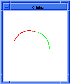
; OUTPUT Original
; Combine the two edges to make a single edge.
(define combine (edge:combine (entity 2) (entity 3)))
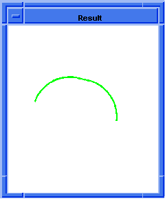
;; combine
; OUTPUT Result
  
Figure.
edge:combine |
[Top]
edge:scan-gaps
- Action
-
Finds all open vertices and checks the distance to the nearest entity.
Filename-
scm/scmext/covr/wire_heal_scm.cpp
APIs-
api_get_edges,
api_get_vertices
Syntax-
(edge:scan-gaps edges)
Arg Types-
Returns-
edge
| (edge ...)
- Arguments
-
edges are input edges.
; edge:scan-gaps
; Find the gap between a vertex to the nearest
; entity.
(define edge1 (edge:linear (position 0 0 0)
(position 10 0 0)))
;; edge1
(define edge2 (edge:linear (position 10 0 0)
(position 10 11 0)))
;; edge2
(define edge3 (edge:linear (position 9 8 0)
(position 0 11 0)))
;; edge3
(define edge4 (edge:linear (position 0 11 0)
(position 0 0 0)))
;; edge4
(define eds (part:entities))
;; eds
(edge:scan-gaps eds)
; acis> (edge:scan-gaps eds)
; vertex (10.0000 11.0000 0.0000) has gap 3.16228
; vertex (9.0000 8.0000 0.0000) has gap 1
;; 3.16227766016838 |
[Top]
edge:set-free
- Action
-
Duplicates an edge and deletes the original.
Filename-
scm/scmext/covr/wire_heal_scm.cpp
APIs-
api_copy_entity_contents,
api_del_entity,
api_get_edges,
api_get_owner
Syntax-
(edge:set-free edges)
Arg Types-
Returns-
edge
| edge ...
Description
Given a list of edges, this command copies all edges that belong to other
topology entities (coedges). All higher level topology entities (coedge,
loop, wire, face, shell, lump, body, etc.) are deleted. Returns a list
of edges that do not have an owner.
- Arguments
-
edges are input edges.
; edge:set-free
; Create solid block.
(define block1
(solid:block (position -20 -20 -20)
(position 20 20 20)))
;; block1
; get list of all edges.
(define edges (entity:edges block1))
;; edges
(define list1 (entity:edges block1))
;; list1
; Free one edge.
(define free (edge:set-free (entity 4)))
; (1 edges) 0
;; free |
[Top]
edge:shortest
- Action
-
Returns the shortest edge in a list.
Filename-
scm/scmext/covr/wire_heal_scm.cpp
APIs-
api_get_edges
Syntax-
(edge:shortest edges)
Arg Types-
Returns-
edge
| (edge ...)
- Arguments
-
edges are input edges.
; edge:shortest
; Find short edges.
; Load a file containing a bad part
(part:load "heal1.sat")
;; (#[entity 2 1] #[entity 3 1] #[entity 4 1]
;; #[entity 5 1])
(zoom-all)
;; #[view 1076700200]
; Combine the faces into a body
(define body1 (hh:combine (list (entity 2)
(entity 3) (entity 4) (entity 5))))
;; body1
; Prepare the body for healing
(define heal (hh:preprocess body1))
;; heal
; #[entity 6 1]
; OUTPUT Original
(hh:analyze-body body1)
; GEOMBUILD CHECK RESULTS
; =========
; Statistics of the body from geombuild check :
; no. of edges = 17
; no. of bad edges = 4
; no. of coedges = 17
; no. of bad coedges = 4
; no. of vertices = 17
; no. of bad vertices = 0
; no. of bad tangent edges = 0
; no. of bad tangent edges analytic = 0
; no. of G1 bad tangent edges analytic = 0
; no. of bad tangent edges uv_uv = 0
; no. of bad tangent edges boundary uv_uv = 0
; no. of bad tangent edges uv_nonuv = 0
; no. of bad tangent edges nonuv_nonuv = 0
; no. of bad tangent edges 3_4_sided = 0
; no. of surfaces = 4
; no. of discontinuous surfaces = 0
; percentage of good geom = 92
;; 92
(edge:shortest body1)
; shortest edge: 4.489976
;; #[entity 7 1] |
[Top]
sheet:cover
- Action
-
Modifies a sheet body by covering each of its simple loops of external
edges by a face.
Filename-
scm/scmext/covr/covr_scm.cpp
APIs-
api_cover_sheet
Syntax-
(sheet:cover body ["multiple"])
Arg Types-
Returns-
body
Description
This extension modifies a sheet body by covering each of its simple loops
of external edges with a face.
A simple external loop of a sheet body is a list of connected edges
where each edge has only a single face. For instance, a block with only
five faces will have an external loop for the edges around the missing
face. This Scheme extension attempts to calculate a surface containing
the edges and creates a face containing the loop of these edges.
For a body with multiple external loops, this extension computes distinct
surfaces for each connected, planar face. For example, a block with uncovered
top and bottom will be closed. Only sheets with single external loops
can be fitted with a NURBS
surface, provided that they contain only three or four edges. In the case
of three edges, a degenerate NURBS
surface is calculated which has a parametric pole on one edge.
The option "multiple" is used
to cover a loop of external edges with multiple planes, if possible. The
default value for "multiple"
is false.
If a surface can not be calculated, a face with no geometric definition
is created and a warning message displayed.
- Arguments
-
body is an input sheet body.
-
"multiple" is used to cover a loop
of external edges with multiple planes, if possible.
; sheet:cover
; Create a solid block.
(define block1
(solid:block (position -20 -20 -20)
(position 20 20 20)))
;; block1
; Get a list of block's faces.
(define faces1 (entity:faces block1))
;; faces1
; Remove the top and front faces.
(define uncover (face:uncover (car faces1)))
;; uncover
(define uncoverlist (face:uncover (car (cdr (cdr (cdr
(cdr faces1)))))))
;; uncoverlist
; Create a sheet body from the wire body.
(define sheetcover (sheet:cover block1))
;; sheetcover |
[Top]
sheet:cover-circuit
- Action
-
Covers a closed circuit of connected edges with a face.
Filename-
scm/scmext/covr/covr_scm.cpp
APIs-
api_cover_circuits
Syntax-
(sheet:cover-circuit (list w1 w2 ...)
[(list w1 w2 w3 ...) (list w1 w2 w3 ...) ... ][fa][ao])
Arg Types-
Returns-
body
Description
This extension covers the provided closed circuits of connected edges with a face.
- Arguments
-
w1 is an input wire body.
-
-
w2 is a second input wire body.
-
-
fa is an input face.
-
-
ao is an optional argument that contains versioning and journaling information.
Limitations-
Edges must form a closed circuit.
(part:clear)
(define b (solid:block 0 0 0 10 10 10))
(define s (solid:sphere 10 10 10 5))
(iso)
(zoom-all)
(define b (solid:subtract b s))
(ray:queue 210.381 91.3469 111.311 -0.834673 -0.344149 -0.42998 1)
(define f (pick-face))
(define elist (entity:edges f))
; remove the face
(entity:delete (face:unhook f))
; cover the hole
(sheet:cover-circuit elist)
(render:rebuild) |
[Top]
sheet:cover-wire-loops
- Action
-
Covers co-planar wires into sheet body having a single planar face.
Filename-
scm/scmext/covr/covr_scm.cpp
APIs-
api_cover_wire_loops
Syntax-
(sheet:cover-wire-loops (list w1 w2 ...))
Arg Types-
Returns-
body
Description
Covers multiple co-planar wire bodies into a sheet body having a single
planar face by converting the first wire in the list into the peripheral
loop and the rest of the wires in the list into the hole loops.
- Arguments
-
list is a required string
that must be included and typed as "list".
-
w1 is a wire body to be the peripheral
loop of the face.
-
w2 is one or more wire bodies to be
the hole loops of the face.
Limitations-
Each wire body can have only one wire.
; sheet:cover-wire-loops
; Create geometry to demonstrate command: create
; 3 wire bodies.
(define wire1 (wire-body (edge:circular
(position 0 0 0) 10 0 360)))
;; wire1
(define wire2 (wire-body (edge:circular
(position 5 0 0) 3 0 360)))
;; wire2
(define wire3 (wire-body (edge:circular
(position -5 0 0) 3 0 360)))
;; wire3
; Cover the wires so wire1 becomes the peripheral
; loop and wire2 becomes the hole loop.
(define sheet (sheet:cover-wire-loops
(list wire1 wire2 wire3)))
;; sheet |
[Top]
sheet:cover-wires
- Action
-
Creates a sheet body from a wire body.
Filename-
scm/scmext/covr/covr_scm.cpp
APIs-
api_check_wire_self_inters,
api_cover_wires
Syntax-
(sheet:cover-wires body [surf] [acis-opts])
Arg Types-
Returns-
body
Description
This extension makes a sheet body from a wire body. It attempts to determine
a surface which contains the edges of each wire. If a surface can be calculated,
it is used for the geometry of the face. If a surface can not be calculated,
a face with no geometric definition is created and a warning message displayed.
The wire must be closed and not self-intersecting. When a face is defined
with the optional surf argument, the
underlying surface of that face is used for the geometry in covering the
wire body.
- Arguments
-
body is an input body.
-
surf when defined the underlying surface
of that face is used for the geometry in covering the wire body.
-
acis-opts contains journaling and versioning
information.
; sheet:cover-wires
; Create circular edge 1.
(define edge1
(edge:circular (position 0 0 0) 20 0 180))
;; edge1
; Create linear edge 2.
; Set a color for edge1
(entity:set-color edge1 2)
;; ()
(define edge2
(edge:linear (position -20 0 0)
(position -20 0 20)))
;; edge2
; Set a color for edge2
(entity:set-color edge2 3)
;; ()
; Create circular edge 3.
(define edge3
(edge:circular (position 0 0 20) 20 0 180))
;; edge3
; Set a color for edge3
(entity:set-color edge3 4)
;; ()
; Create linear edge 4.
(define edge4 (edge:linear (position 20 0 20)
(position 20 0 0)))
;; edge4
; Set a color for edge4
(entity:set-color edge4 6)
;; ()
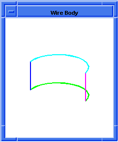
; Create a wire body from the edges.
(define wire_body (wire-body
(list edge1 edge2 edge3 edge4)))
;; wire_body
; OUTPUT Wire Body
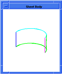
; Create a sheet body from the wire body.
(define sheet_body
(sheet:cover-wires wire_body))
;; sheet_body
; OUTPUT Sheet Body
  
Figure.
sheet:cover-wires |
[Top]
sheet:edge-regions
- Action
-
Repairs coplanar edge vertices within point coincident tolerance to
form regions on a planar sheet.
Filename-
scm/scmext/covr/wire_heal_scm.cpp
APIs-
api_heal_edges_to_regions
Syntax-
(sheet:edge-regions edge-list [coin-tol]
[min-length] [wire] [ao])
Arg Types-
Returns-
body
| wire
Description
This extension takes the list of noncontinuous edges defined in the first
argument (edge-list), snaps the
vertices to the edges, and unites the edges to create a single wire body.
- Arguments
-
edge-list argument calls the
defined edge or edge list for repair.
-
coin-tol argument defines
the minimum tolerance allowed for coincidence. All vertices within the
coincident tolerance are joined.
-
min-length argument defines
the minimum length tolerance allowed.
-
wire argument requires the
string "wire". When this argument is defined, a wire is returned.
-
ao contains journaling and versioning information.
; sheet:edge-regions
; Create topology to illustrate example.
(define edge1 (edge:linear (position 0 0 0)
(position 10 0 0)))
;; edge1
(define edge2 (edge:linear
(position 10.1 0 0) (position 10 10.15 0)))
;; edge2
(define edge3 (edge:linear (position 10 10 0)
(position 0 10 0)))
;; edge3
(define edge4 (edge:linear
(position 0 10.1 0) (position 0.1 0.15 0)))
;; edge4
; Create a sheet from edges that are not continuous.
(define sheet
(sheet:edge-regions (part:entities) 1 0.1))
; stage 1: verify input edge set (4 edges).
; stage 2: snap vertices to edges.
; (8 free vertices)
; > can not snap vertex at position 0.0000
0.0000 0.0000
; > nearest entity is at position 0.0000 10.0000
; 0.0000 (distance 10)
; 8
; 7 vertices snapped.
; 1 edges split.
; stage 3: cleanup overlapping edges
; (5 edges) 4
; stage 4: unite edges into wire body.
; (5 edges) 5
; stage 5: remove edges under length tolerance.
; (5 edges) no short edge.
; stage 6: create regions from edges.
; (sheet:edge-regions) 1 faces created with 4 edges
; shortest edge length
in the faces is 10
; (vs 0.1)
;; sheet
(entity:check sheet)
; checked:
; 1 lumps
; 1 shells
; 0 wires
; 1 faces
; 1 loops
; 4 coedges
; 4 edges
; 4 vertices
;; ()
(define 2d (sheet:2d sheet))
;; 2d
(roll)
;; -1
; Create wire only
(define wire (sheet:edge-regions
(part:entities) 0.1 0.1 "wire"))
; stage 1: verify input edge set (4 edges).
; stage 2: snap vertices to edges.
; (0 free vertices) 0
; stage 3: cleanup overlapping edges
; (4 edges) 3
; stage 4: unite edges into wire body.
; (4 edges) 4
; stage 5: remove edges under length tolerance.
; (4 edges) no short edge.
;; wire
(entity:check wire)
; checked:
; 1 lumps
; 1 shells
; 1 wires
; 0 faces
; 0 loops
; 4 coedges
; 4 edges
; 4 vertices
;; () |
[Top]
sheet:planar-edges
- Action
-
Creates a planar sheet body from a set of planar free edges.
Filename-
scm/scmext/covr/covr_scm.cpp
APIs-
api_cover_planar_edges,
api_get_edges
Syntax-
(sheet:planar-edges edge-list option)
Arg Types-
Returns-
body
Description
This extension makes a planar sheet body from a planar wire body.
- Arguments
-
edge-list is a list of input
edges.
-
option string can be "N" or
"n", stands for nested (circuits). Set to #t for nested circuits (i.e.,
multiple circuits)
; sheet:planar-edges
; create topology to illustrate command.
(define ellipse (edge:ellipse (position 5 5 0)
(gvector 0 0 1) 4))
;; ellipse
(define points1 (wire-body:points (list
(position 0 0 0)
(position 18 0 0) (position 18 10 0)
(position 0 10 0) (position 0 0 0))))
;; points1
(define points2 (wire-body:points (list
(position 4 2 0)
(position 12 2 0) (position 12 8 0)
(position 4 8 0) (position 4 2 0))))
;; points2
(define ellipse2 (edge:ellipse (position 15 5 0)
(gvector 0 0 1) 2))
;; ellipse2
(define points3 (wire-body:points (list
(position 24 2 0)
(position 32 2 0) (position 32 8 0)
(position 24 8 0) (position 24 2 0))))
;; points3
(define ellipse3 (edge:ellipse (position 28 5 0)
(gvector 0 0 1) 3.5))
;; ellipse3
(define eds (edge:set-free (part:entities)))
;; eds
(define sheet (sheet:planar-edges eds))
;; sheet |
[Top]
sheet:planar-wire
- Action
-
Creates a single planar sheet body from a single planar wire body.
Filename-
scm/scmext/covr/covr_scm.cpp
APIs-
api_cover_wires
Syntax-
(sheet:planar-wire body)
Arg Types-
Returns-
body
Description
This extension makes a planar sheet body from planar wire body.
- Arguments
-
body is an input planar wire
body.
; sheet:planar-wire
; Create circular edge 1.
(define edge1
(edge:circular (position 0 0 0) 20 0 180))
;; edge1
; Create linear edge 2.
(define edge2 (edge:linear (position -20 0 0)
(position 20 0 0)))
;; edge2
; Create a wire body from the edges.
(define wire_body
(wire-body (list edge1 edge2)))
;; wire_body
; Create a planar sheet from the wire body.
(define sheet_body
(sheet:planar-wire wire_body))
;; sheet_body |
[Top]
sheet:planar-wires
- Action
-
Covers free planar wires with planar faces.
Filename-
scm/scmext/covr/covr_scm.cpp
APIs-
api_cover_planar_wires
Syntax-
(sheet:planar-wires wire-bodies
["nest" union])
Arg Types-
Returns-
body
Description
This extension makes a planar sheet body from multiple planar wire bodies.
Default is Boolean union.
Sketching a planar wireframe is often the first step of creating a solid
model. This gives users better control over planar entities and can allow
them to attach dimensions/constrains to the sketch. This command assists
in handling unorganized planar entities, such as edges and wires. The
planar entities are covered by planar faces and can be used for later
solid construction operations, such as sweeping, lofting.
- Arguments
-
wire-bodies argument requires
a list of wire bodies as input.
"nest" argument combined with
union argument defined as #f
produces a subtraction. Any other combinations produce a Boolean union.
; sheet:planar-wires
; Create topology to illustrate command.
(define e1 (edge:ellipse (position 0 0 0)
(gvector 0 0 1) 10)))
;; e1
(define w1 (wire-body e1))
;; w1
(define e2 (edge:ellipse (position 0 0 0)
(gvector 0 0 1) 20)))
;; e2
(define w2 (wire-body e2))
;; w2
; hole in the center
(define planar (sheet:planar-wires (list w1 w2)
"nest" #t))
;; planar
(roll)
;; -1
; illustrate command with no hole
(define nohole (sheet:planar-wires (list w1 w2)
"nest" #f))
;; nohole |
[Top]
wire:unite-edges
- Action
-
Unites all edges into a wire body using a non-regularized unite.
Filename-
scm/scmext/covr/wire_heal_scm.cpp
APIs-
api_unite_edges
Syntax-
(wire:unite-edges edges [ao])
Arg Types-
Returns-
body
Description
Performs a non-regularized unite on a list of edges to create a wire body.
The resulting body may have faces, edges, and/or vertices not needed to
support the topology. These are not removed before returning the resulting
body.
- Arguments
-
body is an input body.
-
ao contains journaling and versioning
information.
; wire:unite-edges
; Create topology to illustrate command.
(define edge1 (edge:linear (position -1 0 0)
(position 11 0 0)))
;; edge1
(define edge2 (edge:linear (position 10 -1 0)
(position 10 11 0)))
;; edge2
(define edge3 (edge:linear (position 11 10 0)
(position -1 10 0)))
;; edge3
(define edge4 (edge:linear (position 0 11 0)
(position 0 -1 0)))
;; edge4
(define w (wire:unite-edges (part:entities)))
; (4 edges) 4
;; w
; check for bad wires, geometry, and topology.
(entity:check w)
;; () |
[Top]
© 1989-2007 Spatial Corp., a Dassault Systèmes company. All rights reserved.

![]()


