Scheme Extensions Na thru
Zz
|
|
|
Technical
Article |
| Scheme is a public domain programming language, based on the LISP language, that uses
an interpreter to run commands. ACIS provides extensions (written in C++) to the native Scheme language that can be used by an
application to interact with ACIS through its Scheme Interpreter. The C++ source files for ACIS Scheme extensions are provided
with the product. Spatial's Scheme based demonstration application, Scheme ACIS
Interface Driver Extension (Scheme AIDE), also uses these Scheme extensions and the Scheme
Interpreter.
|
point
- Action
- Creates a point at the specified position.
Filename- scm/scmext/cstr/cstr_scm.cpp
APIs- None
Syntax- (point position)
Arg Types-
Returns- point
Description
position specifies the x, y, and z locations of the point. A point is an entity. A
point is different from a vertex in that it has no edge associations. A point is different
from a position in that a point is saved with the part. Use env:set-point-size and
env:set-point-style
to change its appearance.
- Arguments
- position specifies the x, y, and z locations of the point.
; point
; Create a point.
(define point1 (point (position 6 6 7)))
;; point1
|
[Top]
sheet:1d
- Action
- Modifies a double-sided sheet body into a single-sided sheet body.
Filename- scm/scmext/cstr/sht_scm.cpp
APIs- api_body_to_1d
Syntax- (sheet:1d body [fix-normals=#t [ref-faces]] [ao])
Arg Types-
Returns- body
Errors- The input body is NULL,
one of more of the entities in ref-faces is not a face,
one or more of the faces in ref-faces is owned by another body, or
two or more of the faces in ref-faces belong to the same shell.
Description
This extension converts the double-sided faces of the input body to
single-sided faces. The argument body is the input body.
When fix-normals is set to FALSE, this extension merely
marks the faces as single-sided, without checking to see if the faces
on the resulting single-sided body have consistent normal directions. For
performance purposes, the user may want to use this setting when confident
that no such inconsistencies exist. In order to guard against the creation
of an invalid body, we recommend that this flag be set to TRUE
(its default value). In that case, the user may provide a list of faces
(one on each shell of the body) via the argument ref-faces, which
specifies those faces whose normals are to remain unchanged if any face normals
are found to have an inconsistent orientation. If this argument is not provided,
or if any of the body's shells is not represented in the list, this function
uses the first face on each of the unrepresented shells to determine the
orientation of the result.
Note: Support for the fix-normals option does not extend
to either non-manifold bodies, or to non-orientable manifold sheets (for example,
a Moebius strip). If this option is nevertheless used in conjunction with such
objects, undesirable results can occur. In the case of non-manifold bodies,
face normals may be partially adjusted; in the case of non-orientable sheets,
a system error (UNSUPPORTED_TOPOLOGY) will be thrown.
- Arguments
- body is an input sheet body.
fix-normals determines if the
faces need to be marked as single-sided, with or without checking to see if
the faces on the resulting single-sided body have consistent normal directions.
ref-faces specifies those faces whose
normals are to remain unchanged if any face normals are found to have an inconsistent
orientation.-
ao contains journaling and versioning information.
Limitations- The fix-normals option is not supported for non-manifold bodies or for
non-orientable manifold sheets.
; sheet:1d
; Create a planar face.
(define face1 (face:plane (position 0 0 15) 50 50))
;; face1
; Change the planar face to a sheet body.
(define sheet1 (sheet:face face1))
;; sheet1
; Change the sheet body into
; a double sided sheet body.
(define sheet2 (sheet:2d sheet1))
;; sheet2
; Change the body back into a single sided body.
(define sheet3 (sheet:1d sheet1))
;; sheet3
|
[Top]
sheet:2d
- Action
- Modifies a single-sided sheet body into a double-sided sheet body.
Filename- scm/scmext/cstr/sht_scm.cpp
APIs- api_body_to_2d
Syntax- (sheet:2d body [ao])
Arg Types-
Returns- body
Description
This extension modifies a single-sided sheet body, which is solid on one side
and void on the other side, into a double-sided sheet body, which is void on
both sides. A sheet body is infinitely thin.
In the following example, the sheet body is solid (material) on both
sides. Also, refer to the example for sheet:face.
- Arguments
- body is an input sheet body.
-
ao contains journaling and versioning information.
; sheet:2d
; Create a planar face.
(define face1 (face:plane (position 0 0 15) 50 50))
;; face1
; Change the planar face to a sheet body.
(define sheet1 (sheet:face face1))
;; sheet1
; Change the sheet body into
; a double sided sheet body.
(define 2d (sheet:2d sheet1))
;; 2d
; Create a solid cylinder.
(define cylinder1
(solid:cylinder (position 25 25 0)
(position 25 25 30) 15))
;; cylinder1
; Change the eye position for better viewing.
(view:set-eye (position 20 200 30))
;; #[position 100 -200 100]
(define refresh (view:refresh))
;; refresh
; Unite the double-sided sheet body
; with the cylinder.
(define creation (solid:unite sheet1 cylinder1))
;; creation
|
[Top]
sheet:enclose
- Action
- Converts a closed 2D sheet into a solid volume.
Filename- scm/scmext/cstr/sht_scm.cpp
APIs- api_enclose_void
Syntax- (sheet:enclose face side [lumps=#f])
Arg Types-
Returns- body
Description
Converts the void volume of a face into a filled volume. It changes the containment
information of all the faces in the minimal volume enclosing set related to the specified
side of the original face. The argument side is the REVBIT sense, telling it to take the
current inside/outside markings or to reverse them. The return body is the owner of the
face.
Optional argument lumps indicates that the algorithm should determine
if any distinct lumps are contained within the old void and should process them by
repairing their external face containment information; otherwise, such processing is not
performed.
This routine walks outward from the face along the closest radial
enclosing faces until a volume is enclosed or NULL coedges are encountered. It changes the
containment data on the faces that are detected so they no longer contain a void. An
outside face is changed to single-sided (unless it is detected twice in the search) and a
single-sided face is changed to inside. Requires no action if the side of the face given
is already a material containing.
- Arguments
- face is an input face argument.
side is the REVBIT sense, telling it to take the current inside/outside
markings or to reverse them.
lumps indicates that the algorithm should determine if any distinct
lumps are contained within the old void and should process them by repairing their
external face containment information; otherwise, such processing is not performed.
; sheet:enclose
; Converts the volume of a face into a filled volume.
; Create solid block 1
(define block1
(solid:block (position -50 -50 -50)
(position 50 50 50)))
;; block1
; Change the view size for better viewing.
(view:compute-extrema)
;; ()
(define refresh (view:refresh))
;; refresh
; Create solid block 2.
(define block2
(solid:block (position -25 -25 -25)
(position 25 25 25)))
;; block2
; Subtract block 2 from block 1 to create a
; void volume inside the larger block.
(define subtract (solid:subtract block1 block2))
;; subtract
(define 2d (sheet:2d block1))
;; 2d
(solid:massprop block1)
;; (("volume" . 0) ("accuracy achieved" . 0))
(define enclose (sheet:enclose (pick:face
(ray (position 0 0 0) (gvector 0 0 1)) 1) #f #t))
;; enclose
(solid:massprop block1)
;; (("volume" . 875000) ("accuracy achieved" . 0))
|
[Top]
sheet:face
- Action
- Creates a sheet body from a given face.
Filename- scm/scmext/cstr/sht_scm.cpp
APIs- api_mk_by_faces
Syntax- (sheet:face face)
Arg Types-
Returns- body
Description
This extension creates a single-sided sheet body from a given face. A sheet body is
similar to a solid body except a sheet body is infinitely thin.
In the following example, note the solid side of the sheet body
(material) and the void side (air).
- Arguments
- face is an input face argument.
; sheet:face
; Create a face.
(define face1 (face:plane (position 0 0 15) 50 50))
;; face1
; Create a sheet body from a face.
(define sheet1 (sheet:face face1))
;; sheet1
|
[Top]
sheet:face1
- Action
- Creates a sheet body from a given face.
Filename- scm/scmext/cstr/sht_scm.cpp
APIs- api_sheet_from_ff
Syntax- (sheet:face face ao)
Arg Types-
Returns- body
Description
This extension creates a single-sided sheet body from a given face. A sheet body is
similar to a solid body except a sheet body is infinitely thin.
In the following example, note the solid side of the sheet body
(material) and the void side (air).
- Arguments
- face is an input face argument.
- ao contains journaling and versioning information.
; sheet:face1
; Create a face.
(define face1 (face:plane (position 0 0 15) 50 50))
;; face1
; Create a sheet body from a face.
(define sheet1 (sheet:face face1))
;; sheet1
|
[Top]
sheet:face2
- Action
- Creates a sheet body from a given face.
Filename- scm/scmext/cstr/sht_scm.cpp
APIs- api_sheet_from_ff
Syntax- (sheet:face faces ao)
Arg Types-
Returns- body
Description
This extension creates a single-sided sheet body from a given face. A sheet body is
similar to a solid body except a sheet body is infinitely thin.
In the following example, note the solid side of the sheet body
(material) and the void side (air).
- Arguments
- face is an input face argument.
ao contains journaling and versioning information.
; sheet:face2
; Create a face.
(define face1 (face:plane (position 0 0 15) 50 50))
;; face1
; Create a sheet body from a face.
(define sheet1 (sheet:face2 face1))
;; sheet1
|
[Top]
solid:area
- Action
- Returns the surface area of a solid.
Filename- scm/scmext/cstr/sld_scm.cpp
APIs- api_ent_area
Syntax- (solid:area solid-body [tolerance=0.01] [ao])
Arg Types-
Returns- pair
Description
The first argument, solid-body, specifies a solid body.
The second argument is an optional tolerance, which specifies the requested relative accuracy
of the calculation. This value is expressed as a proportion, so the default value of 0.01
requests that the value returned be within 1% of the true area. This extension returns a pair
of values: the total face area of the body and the relative accuracy (absolute area/error)
achieved in the computation.
- Arguments
- solid-body specifies a solid body.
tolerance specifies the accuracy of the calculation.
ao contains journaling and versioning information.
; solid:area
; Create a solid block.
(define block1
(solid:block (position 0 0 0)
(position 8 8 8)))
;; block1
; Get the area of the block to the default 1% accuracy
(solid:area block1)
;; (384 . 0)
; Get the area of the block to an accuracy of 0.01%
(solid:area block1 0.0001)
;; (384 . 0)
; Create a solid sphere.
(define sphere1
(solid:sphere (position -5 -5 -5) 15))
;; sphere1
; Find the area of the sphere.
(solid:area sphere1)
;; (2827.43338823081 . 0)
; Unite the two solids into one entity.
(define combo1 (solid:unite sphere1 block1))
;; combo1
; Find the area of new solid with an accuracy of 0.1%
(solid:area combo1 0.001)
;; (3002.89739498109 . 5.16140236906182e-006)
|
[Top]
solid:block
- Action
- Creates a solid block.
Filename- scm/scmext/cstr/sld_scm.cpp
APIs- api_solid_block
Syntax- (solid:block {{diagonal1 diagonal2 | (diagonal-x1
diagonal-y1 diagonal-z1 diagonal-x2 diagonal-y2
diagonal-z2)}} [ao])
Arg Types-
Returns- entity
Description
The argument diagonal1 specifies the first diagonal corner. The argument diagonal2
specifies the second diagonal corner. As you can see, there are two syntax formats
available for defining the positional arguments. The first (original) syntax format
defines the diagonal positions by placing the positions in "position" statements
enclosed in parentheses (as shown in the example below with creating block1). However, the
second syntax format defines the diagonal positions without using the "position"
statement or the additional set of parentheses (as shown in the example below with
defining block2 and block3). The two formats are otherwise identical and accomplish the
same. The format you choose must be used for both of the positional arguments.
The block is oriented with respect to the current WCS.
- Arguments
- diagonal1 specifies the first diagonal corner.
diagonal2 specifies the second diagonal corner.
diagonal-x1, diagonal-y1, diagonal-z1 specifies the first positional
arguments.
diagonal-x2, diagonal-y2, diagonal-z2 specifies the second positional
arguments.-
ao contains journaling and versioning information.
; solid:block
; Create first solid block.Use "position" syntax
; format for defining the diagonals.
(define block1
(solid:block (position 0 0 0)
(position 20 20 20)))
;; block1
; Set the color of block1
(entity:set-color block1 2)
;; ()
; Create 2nd solid block. Use alternate position
; argument format.
(define block2
(solid:block 10 10 0 20 20 40))
;; block2
; Set the color of block2
(entity:set-color block2 3)
;; ()
; Create 3rd solid block. Use alternate position
; argument format.
(define block3
(solid:block 0 0 0 -30 -20 -5))
;; block3
; Set the color of block3
(entity:set-color block3 4)
;; ()
; OUTPUT Examples
Figure. solid:block.
|
[Top]
solid:closed?
- Action
- Verifies if a Scheme object is a closed solid.
Filename- scm/scmext/cstr/sld_scm.cpp
APIs- None
Syntax- (solid:closed? object)
Arg Types-
Returns- boolean
- Arguments
- object is an input scheme object.
; solid:closed?
; Create a solid closed to query.
(define block1 (solid:block (position 0 0 0)
(position 40 40 40)))
;; block1
; Verify block1 is closed.
(solid:closed? block1)
;; #t
; Create a face to convert to solid sheet.
(define face1 (face:plane (position 0 0 15) 50 50))
;; face1
; Convert face to a solid sheet.
(define sheet1 (sheet:face face1))
;; sheet1
; Verify this is a solid.
(solid? sheet1)
;; #t
; Verify sheet1 is non-closed.
(solid:closed? sheet1)
;; #f
|
[Top]
solid:cone
- Action
- Creates a right circular cone.
Filename- scm/scmext/cstr/sld_scm.cpp
APIs- api_solid_cylinder_cone
Syntax- (solid:cone {{start-axis end-axis} | {start-axis-x
start-axis-y start-axis-z end-axis-x end-axis-y
end-axis-z}} base-radius top-radius
[ratio=1 [position3 | {x3 y3 z3}]])
Arg Types-
Returns- entity
Description
The argument start-axis specifies the start axis position or base of the cone. The
argument end-axis specifies the end axis position or top of the cone. As you can see,
there are two syntax formats available for defining these positional arguments. The first
(original) syntax format defines all positional arguments by placing them in
"position" statements enclosed in parentheses (as shown in the example below
with creating cone1). However, the second syntax format defines positional arguments
without using the "position" statement or the additional set of parentheses (as
shown in the example below with defining cone2 and cone3). The two formats are otherwise
identical and accomplish the same. The format you choose must be used for all three of the
positional arguments.
The argument base-radius
specifies the radius at start-axis (must be greater than zero).
The argument top-radius specifies the radius at end-axis (which can be
zero).
If the optional arguments ratio and position3 are specified, an
elliptical cone is created. If ratio is specified, the ratio between the major and minor
axis of the ellipse is used. If position3 (or x3, y3, and z3) is specified, the vector
from the projection of position3 (or x3, y3, and z3) onto the axis of the cone to
position3 (or x3, y3, and z3) specifies the major axis. If position3 (or x3, y3, and z3)
is not specified, the major axis is defined by the projection of the x-axis of the
active work coordinate system onto the plane that is defined by start-axis and the vector
from start-axis to end-axis.
Note: position3 cannot lie
on the axis of the cone or an error occurs.
- Arguments
- start-axis specifies the start axis position or base of the cone.
end-axis specifies the end axis position or top of the cone.
start-axis-x, start-axis-y, start-axis-z are syntax formats available
for defining start-axis positional arguments.
end-axis-x, end-axis-y, end-axis-z are syntax formats available for
defining end-axis positional arguments.
base-radius specifies the
radius at start-axis (must be greater than zero).
top-radius specifies the
radius at end-axis (which can be zero).
ratio is the ratio between the major and minor axis of the ellipse.
position3 (or x3, y3, and z3) is the vector from the projection of
position3 (or x3, y3, and z3) onto the axis of the cone to position3 (or x3, y3, and z3).
x3, y3, z3 are syntax formats available for defining position3
positional arguments.
Limitations-
Positional arguments format must be consistent. Refer to Description.
; solid:cone
; Create first cone. Use "position" syntax format
; for defining the starting and ending axis
; positions.
(define cone1
(solid:cone (position -20 -5 -9)
(position 15 20 10) 10 2))
;; cone1
; OUTPUT Definition
; Set a color for cone1
(entity:set-color cone1 2)
;; ()
; Create second cone. Use alternate position argument
; format. Define radius of base and top.
(define cone2
(solid:cone -20 -5 -9 5 15 7.5 10 2 3))
;; cone2
; Set a color for cone2
(entity:set-color cone2 3)
;; ()
; Create 3rd cone using alternate position argument
; format. Define radius of base and top. Add ratio
; and 3rd position.
(define cone3
(solid:cone -2 -5 -9 15 20 10 10 2 3 17 22 12))
;; cone3
; Set a color for cone3
(entity:set-color cone3 4)
;; ()
; OUTPUT Examples
Figure. solid:cone
|
[Top]
solid:cylinder
- Action
- Creates a right circular cylinder.
Filename- scm/scmext/cstr/sld_scm.cpp
APIs- api_solid_cylinder_cone
Syntax- (solid:cylinder {{start-pos end-pos} | {x-start
y-start z-start x-end y-end z-end}} radius
[ratio=1 {position3 | {x3 y3 z3}}])
Arg Types-
Returns- entity
Description
The argument start-pos or (or x-start, y-start, and z-start) specifies the start
position of the cylinder. The argument end-pos ( or x-end, y-end, and z-end) specifies the
end position of the cylinder. As you can see, there are two syntax formats available for
defining the starting and ending positions for creating a cylinder. The first (original)
syntax format defines the positional arguments by placing them in "position"
statements enclosed in parentheses (as shown in the example below with creating cyl1).
However, the second syntax format defines the positional arguments without using the
"position" statement or the additional set of parentheses (as shown in the
example below with defining cyl2 and cyl3). The two formats are otherwise identical and
accomplish the same. The format you choose must be used for all three of the positional
arguments.
The argument radius specifies the radii for the base and top.
If the optional arguments ratio and position3 (or x3, y3, and z3) are
specified, an elliptical cylinder is created. If ratio is specified, the ratio between the
major and minor axis of the ellipse is used. If position3 (or x3, y3, and z3) is
specified, the vector from the projection of position3 (or x3, y3, and z3) on to the axis
of the cylinder to position3 (or x3, y3, and z3) specifies the major axis. If position3
(or x3, y3, and z3) is not specified, the major axis is defined by the projection of the x-axis
of the active work coordinate system onto the plane that is defined by position1 and the
vector from position1 to position2.
Note: position3 cannot lie
on the axis of the cylinder or an error occurs.
- Arguments
- start-pos specifies the start position of the cylinder.
x-start, y-start, and z-start specifies the start position of the
cylinder.
end-pos specifies the end position of the cylinder.
x-end, y-end, and z-end specifies the end position of the cylinder.
ratio is the ratio between the major and minor axis of the ellipse.
position3 (or x3, y3, and z3) is the vector from the projection of
position3 (or x3, y3, and z3) on to the axis of the cylinder to position3 (or x3, y3, and
z3).
x3, y3, and z3 are the syntax arguments for position3 argument.
Limitations-
Positional arguments format must be consistent. Refer to Description.
; solid:cylinder
; Create solid cylinder 1.
(define cyl1
(solid:cylinder (position 0 0 0)
(position 25 25 0) 30))
;; cyl1
; OUTPUT Definition
; Set a color for cyl1
(entity:set-color cyl1 2)
;; ()
; Create solid cylinder 2.
(define cyl2
(solid:cylinder 2 2 2 -20 -20 0 15 3))
;; cyl2
; Set a color for cyl2
(entity:set-color cyl2 3)
;; ()
; Create solid cylinder 3.
(define cyl3
(solid:cylinder 2 2 2 -20 -20 0 15 3 -5 -5 0))
;; cyl3
; Set a color for cyl3
(entity:set-color cyl3 4)
;; ()
; OUTPUT Example
  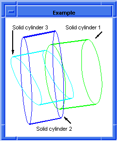
Figure. solid:cylinder
|
[Top]
solid:manifold?
- Action
- Verifies if a Scheme object is a manifold solid.
Filename- scm/scmext/cstr/sld_scm.cpp
APIs- api_manifold_class
Syntax- (solid:manifold? object)
Arg Types-
Returns- boolean
- Arguments
- object is an input scheme-object.
; solid:manifold?
; Create a solid manifold to query.
(define body1 (solid:block (position 0 0 0)
(position 40 40 40)))
;; body1
; Verify body1 is manifold.
(solid:manifold? body1)
;; #t
(part:clear)
;; #t
; Create a nonmanifold solid to query.
; Start with a block
(define blank (solid:block 0 0 0 40 40 40))
;; blank
; Make another block rotated about one edge.
(define tool (entity:transform (entity:copy blank)
(transform:rotation (position 0 0 0)
(gvector 0 0 1) 180)))
;; tool
; Unite the two blocks along their common edge to form body2.
(define body2 (solid:unite blank tool))
;; body2
; Verify body2 is non-manifold.
(solid:manifold? body2)
;; #f
|
[Top]
solid:massprop
- Action
- Obsolete: Use body:massprops instead.
Analyzes the mass properties of a solid.
Filename- scm/scmext/cstr/sld_scm.cpp
APIs- None
Syntax- (solid:massprop entity [integer-type=0 [thickness] tolerance=1
{{position=center} | {x=center-x y=center-y
z=center-z}} direction=z-axis])
Arg Types-
Returns- (position
| gvector
| real
| integer
| string ...)
Description
The argument entity must be a solid body to compute the mass properties. The optional
integer-type specifies the type of calculation to perform. The argument tolerance
specifies the accuracy desired. Set the requested tolerance (accuracy) to the desired relative error as a percentage.
For example, entering 1 requests a maximum error of one percent. Note that with the corresponding API,
api_body_mass_pr,
the accuracy should be passed as the decimal value: thus, using a tolerance of 1 in Scheme
with (solid:massprop) equates to calling api_body_mass_pr with a value
for the req_rel_accy parameter of 0.01.
The optional argument position specifies a point on the projection
plane for the moment and can be defined with either of two syntax formats. The first
syntax defines position by placing the xyz coordinates in "position" statements
enclosed in parentheses. However, the second syntax format defines the xyz coordinates
without using the "position" statements or the additional set of parentheses (as
shown in the example below). The two formats are otherwise identical and accomplish the
same.
The optional argument direction specifies the normal to the projection
plane for the moments; the default is the z-axis of the active work coordinate
system.
Valid values include:
0= Volume and tolerance
only.
1= Volume, tolerance,
center of mass, principal moments, and principal axes.
2= Volume, center of
mass, principal moments, principal axes, inertial tensor.
3= Volume and tolerance
only, using thickness for double-sided faces
4= Volume, tolerance and
center of mass, using thickness for double-sided faces
5= Volume, center of
mass, principal moments, principal axes, inertia tensor, using thickness for double-sided
faces.
For types 3-5 inclusive, a non-negative thickness argument is required
(after the type, before the tolerance if given), which is used to ascribe mass properties
to any double-sided faces that the body contains. For types 0-2, double-sided sheets are
ignored - they are treated as having zero volume, hence no mass and no influence on the
center of mass or inertia. This is equivalent to using types 3-5 with a thickness of zero.
Wire bodies are always treated as having zero volume and no influence on the center of
mass or inertia.
- Arguments
- entity must be a solid body to compute the mass properties.
integer-type specifies the type of calculation to perform.
thickness specifies the thickness required.
tolerance specifies the accuracy desired.
position specifies a point on the projection plane for the moment.
x, y, z are the positional arguments.
direction specifies the normal to the projection plane for the moments.
; solid:massprop
; Create a solid block.
(define block1
(solid:block 0 0 0 15 15 15))
;; block1
; Determine the mass properties of the block
; using various methods.
(solid:massprop block1)
;; (("volume" . 3375) ("accuracy achieved" . 0))
(solid:massprop block1 1)
;; (("volume" . 3375) ("accuracy achieved" . 0)
;; ("center of mass" . #[position 7.5 7.5 7.5]))
(solid:massprop block1 2)
;; (("volume" . 3375) ("accuracy achieved" . 0)
;; ("center of mass" . #[position 7.5 7.5 7.5])
;; ("principal moment x" . 126562.5)
;; ("principal axis x" . #[gvector 1 0 0])
;; ("principal moment y" . 126562.5)
;; ("principal axis y" . #[gvector 0 1 0])
;; ("principal moment z" . 126562.5)
;; ("principal axis z" . #[gvector 0 0 1])
;; ("inertia tensor" 506250 189843.75 189843.75
;; 189843.75 506250 189843.75 189843.75
;; 189843.75 506250))
(solid:massprop block1 1 0.03 6 3 8 (gvector 0 0 1))
;; (("volume" . 3375) ("accuracy achieved" . 0)
;; ("center of mass" . #[position 7.5 7.5 7.5]))
|
[Top]
solid:prism
- Action
- Creates a solid prism.
Filename- scm/scmext/cstr/sld_scm.cpp
APIs- api_make_prism
Syntax- (solid:prism height major-radius minor-radius nsides)
Arg Types-
Returns- entity
Description
Creates an nsides-sided prism where n is greater than or equal to three. The prism is
centered about the origin with its height along the z-axis, the major-radius
along the x-axis, and the minor-radius along the y-axis. If height is zero, the
resulting body consists of just one polygonal-sided sheet face, lying in the xy
plane.
- Arguments
- height height along the z-axis.
major-radius radius along
the x-axis.
minor-radius radius along
the y-axis.
nsides number of sides of the prism where n is greater than or equal to
three.
; solid:prism
; Create a solid prism.
(define prism (solid:prism 20 40 40 6))
;; prism
; OUTPUT Example
(render)
;; ()
; OUTPUT Rendered Prism
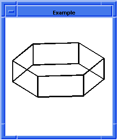  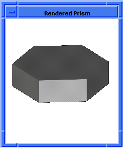
Figure. solid:prism
|
[Top]
solid:pyramid
- Action
- Creates a solid pyramid.
Filename- scm/scmext/cstr/sld_scm.cpp
APIs- api_make_pyramid
Syntax- (solid:pyramid height major-radius minor-radius nsides
[top])
Arg Types-
Returns- entity
Errors- Either major-radius or minor-radius is less than resabs or height is greater than zero and less than resabs or top is less than -resabs or nsides is less than 3.
Description
Creates a solid pyramid. The number of sides must be greater than or equal to three.
The prism is centered about the origin with its height along the z-axis, the
major-radius along the x-axis, and the minor-radius along the y-axis. The argument
top specifies the major axis length at the top of the pyramid. If the height is zero, the
resulting body consists of just one polygonal-sided sheet face, lying in the xy
plane.
- Arguments
- height is a height along the z-axis.
major-radius radius along the x-axis.
minor-radius radius along the y-axis.
nsides number of sides of the pyramid where n is greater than or equal
to three.
top specifies the major axis length at the top of the pyramid.
; solid:pyramid
; Create a solid pyramid.
(define pyramid (solid:pyramid 20 40 40 4 10))
;; pyramid
; OUTPUT Example
(render)
;; ()
; OUTPUT Rendered Pyramid
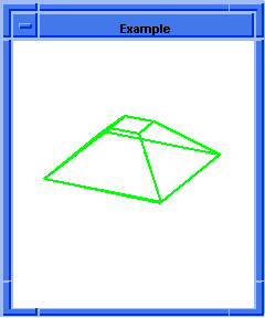  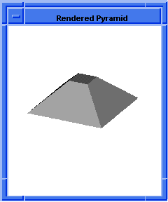
Figure. solid:pyramid
|
[Top]
solid:sphere
- Action
- Creates a sphere centered at the specified position.
Filename- scm/scmext/cstr/sld_scm.cpp
APIs- api_solid_sphere
Syntax- (solid:sphere {center-position | {center-x center-y
center-z}} radius)
Arg Types-
Returns- entity
Description
Creates a sphere centered at the specified position. center-position specifies the
center position of the sphere. There are two syntax formats available for defining the
center-position. The first (original) syntax format defines the center-position by placing
the xyz coordinates in a "position" statement enclosed in parentheses (as shown
in the example below with creating sphere1). However, the second syntax format defines the
center position xyz coordinates without using the "position" statement or the
additional set of parentheses (as shown in the example below with defining sphere2 and
sphere3). The two formats are otherwise identical.
- Arguments
- center-position specifies the center position of the sphere
center-x, center-y, center-z is the syntax for the positional argument
center-position.
radius determines the size of the sphere.
; solid:sphere
; Create first sphere. Use "position" syntax format
; for defining the positions.
; Create solid sphere1.
(define sphere1
(solid:sphere (position -4 -4 0) 1.5))
;; sphere1
; Create 2nd sphere.Use alternate position argument
; format. Define radius.
(define sphere2
(solid:sphere -30 0 0 15))
;; sphere2
; Create solid sphere 3.
; Define 2nd sphere using alternate position argument
; format. Define radius.
(define sphere3 (solid:sphere 10 10 10 5)))
;; sphere3
; OUTPUT Example
(render)
;; OUTPUT Rendered Spheres
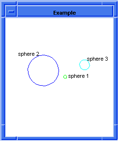  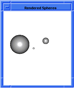
Figure. solid:sphere
|
[Top]
solid:torus
- Action
- Creates a solid torus.
Filename- scm/scmext/cstr/sld_scm.cpp
APIs- api_solid_torus
Syntax- (solid:torus {center-position | {center-x center-y
center-z}} major-radius minor-radius)
Arg Types-
Returns- entity
Description
This extension creates a solid torus of given radii centered at the origin. The torus
is defined in the xy plane of the active coordinate system and oriented using the
active coordinate system's normal gvector.
The argument center-position specifies the center location of the
torus. There are two syntax formats available for this argument. The first (original)
syntax format defines the center-position by placing it in a "position"
statement enclosed in parentheses (as shown in the example below with creating torus1).
However, the second format defines the xyz coordinates of the center position without
using the "position" statement or the additional set of parentheses (as shown in
the example below with defining torus2 and torus3). The two formats are otherwise
identical.
The argument major-radius specifies the distance from the center to the
spine curve lying in this plane. It is specified around a circle having the minor axis. It
is swept to define the torus.
Three shapes of tori may be specified: donut, apple, or lemon depending
on the relative magnitudes of the major and minor radii. If the major-radius is greater
than the minor-radius, the torus is a donut. If the major-radius is positive but smaller
than the minor-radius, the torus is an apple. If the major-radius is negative, the torus
is a lemon.
- Arguments
- center-position specifies the center position of the torus.
center-x, center-y, center-z is the syntax for the positional argument
center-position..
major-radius specifies the distance from the center to the spine curve
lying in this plane.
minor-radius is the minor radius of the torus.
; solid:torus
; Create solid torus 1.
(define torus1
(solid:torus (position -10 -5 -10) 7 3))
;; torus1
; Create solid torus 2.
(define torus2
(solid:torus 10 15 20 10 5))
;; torus2
; OUTPUT Example
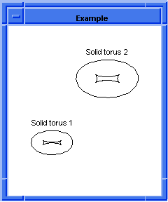
Figure. solid:torus
|
[Top]
solid:wiggle
- Action
- Creates a rectangular block with a spline surface top.
Filename- scm/scmext/cstr/sld_scm.cpp
APIs- api_wiggle
Syntax- (solid:wiggle width depth height
{wiggle-type | shape1 shape2 shape3 shape4})
Arg Types-
Returns- entity
Description
Constructs a rectangular block with a wiggly top, for simple testing of sculptured
surfaces. If height is 0, it constructs a sheet body, which contains one single-sided
wiggly face.
- It constructs four splines for the edges. Each is a cubic B-spline with
two spans, passing through three collinear points. The shape is specified by the
appropriate integer argument, as follows:
0= straight line.- 1= "s" shape,
starting at low parameter value with a 45 degree upward (positive z) tangent, and
ending at high parameter in the same direction.
- 2= double hump, starting
going upwards and ending downwards.
- -1= same as 1, but inverted.
- -2= same as 2, but inverted.
- The wiggle edge shapes are set as:
shape1
= low v-parameter- shape2
= high v-parameter
- shape3
= low u-parameter
- shape4
= high u-parameter
The asymmetric (wiggle-type "anti") option sets the shape boundaries to
1, -2, 2, and 1, and the symmetric (wiggle-type "sym") option sets the boundaries to 1, -2,
-2, and -1.
- Arguments
- width of a rectangular block with a wiggly top.
depth of a rectangular block with a wiggly top.
height of a rectangular block with a wiggly top.
wiggle-type is a type of wiggle.
shape1 is a shape of a wiggle having low v-parameter.
shape2 is a shape of a wiggle having high v-parameter.
shape3 is a shape of a wiggle having low u-parameter.
shape4 is a shape of a wiggle having high u-parameter.
; solid:wiggle
; Create solid wiggle 1.
(define wiggle1 (solid:wiggle 25 25 25 "anti"))
;; wiggle1
; Set a color for wiggle1
(entity:set-color wiggle1 2)
;; ()
; Create solid wiggle 2.
(define wiggle2 (solid:wiggle 40 40 40 1 -1 2 -2))
;; wiggle2
; Set a color for wiggle2
(entity:set-color wiggle2 3)
;; ()
; OUTPUT Example
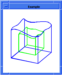
Figure. solid:wiggle
|
[Top]
splgrid
- Action
- Creates a spline grid structure data type.
Filename- scm/scmext/cstr/sgrd_scm.cpp
APIs- None
Syntax- (splgrid)
Arg Types-
Returns- splgrid
Description
This extension creates a data structure used for holding the spline surface grid
information needed to create a spline surface. It determines a spline face in terms of an
array of positions. A spline face is defined in uv space. Therefore, the splgrid is
defined as an array with u and v indices. The splgrid data structure
contains: the number of u and v indices, the tolerance, the specified grid
array, the tangent vectors starting on u, the tangent vectors ending on u,
the tangent vectors starting on v, and the tangent vectors ending on v.
A face can be created using the data from the spline grid data
structure. The points defined and other tangents are interpolated to create the face using
the face:spline-grid command.
; splgrid
; Create a spline grid.
(define grid1 (splgrid))
;; grid1
; Define a spline grid.
(define grid2 (splgrid))
;; grid2
(define print (splgrid:print grid1))
; Num_u 0, Num_v 0
; Tolerance: 0.000001
; Grid Array:
; Tangent Vectors u-start:
; Vector list has not been established
; Tangent Vectors u-end:
; Vector list has not been established
; Tangent Vectors v-start:
; Vector list has not been established
; Tangent Vectors v-end:
; Vector list has not been established
;; print
|
[Top]
splgrid:copy
- Action
- Copies a spline grid structure data type.
Filename- scm/scmext/cstr/sgrd_scm.cpp
APIs- None
Syntax- (splgrid:copy grid)
Arg Types-
Returns- splgrid
Description
Makes a copy of a spline grid structure data type. The argument grid specifies the
spline grid object to copy.
A face can be created using the data from the spline grid data
structure. The points defined and other tangents are interpolated to create the face using
the face:spline-grid command.
- Arguments
- grid is an input spline grid.
; splgrid:copy
; Define a spline grid.
(define grid1 (splgrid))
;; grid1
; Copy a splgrid object.
(define grid2 (splgrid:copy grid1))
;; grid2
|
[Top]
splgrid:point-item
- Action
- Gets a single point from a list of points of a spline grid data structure.
Filename- scm/scmext/cstr/sgrd_scm.cpp
APIs- None
Syntax- (splgrid:point-item grid row column)
Arg Types-
Returns- position
Description
Gets a single point from a list of points of a spline grid data structure. The argument
row specifies the u row index of the grid. The argument column specifies the v
column index of the grid.
- Arguments
- grid is an input spline grid.
row specifies the u row index of the grid.
column specifies the v column index of the grid.
; splgrid:point-item
; Define a spline grid.
(define grid1 (splgrid))
;; grid1
; Define a list of points.
(define points1 (list
(position -10 -10 20) (position -5 0 10)
(position -20 20 30) (position -20 -15 10)
(position -30 -10 0) (position -30 25 -30)
(position 0 -10 -20) (position 5 -12 -30)
(position 0 15 15) (position 30 -6 -5)
(position 25 -10 0) (position 30 25 -30)
(position 10 -10 10) (position 25 -10 20)
(position 20 20 30)))
;; points1
; Set a list of points that define the spline grid.
(define gridlist
(splgrid:set-point-list grid1 points1 3 3))
;; gridlist
; Get a single point from the list of points.
(splgrid:point-item grid1 0 0)
;; #[position -10 -10 20]
; Change a single point in the list of points.
(define griditem (splgrid:set-point-item grid1 0 0
(position 30 30 30)))
;; griditem
; Get a single point from the list of points.
(splgrid:point-item grid1 0 0)
;; #[position 30 30 30]
|
[Top]
splgrid:print
- Action
- Prints the splgrid data.
Filename- scm/scmext/cstr/sgrd_scm.cpp
APIs- None
Syntax- (splgrid:print grid)
Arg Types-
Returns- splgrid
- Arguments
- grid is an input spline grid.
; splgrid:print
; Define a spline grid.
(define grid1 (splgrid))
;; grid1
; Define a list of points.
(define points1 (list
(position -50 -50 0) (position 0 -50 50)
(position 50 -50 0) (position -50 0 50)
(position 0 0 100) (position 50 0 50)
(position -50 50 0) (position 0 50 50)
(position 50 50 0)))
;; points1
; Set a list of points that define the spline grid.
(define gridlist
(splgrid:set-point-list grid1 points1 3 3))
;; gridlist
; Print splgrid data.
(define print (splgrid:print grid1))
; Num_u 3, Num_v 3
; Tolerance: 0.000001
; Grid Array:
; -50.000000-50.0000000.000000
; 0.000000 -50.00000050.000000
; 50.000000 -50.0000000.000000
;
; -50.0000000.000000 50.000000
; 0.000000 0.000000 100.000000
; 50.000000 0.000000 50.000000
;
; -50.00000050.000000 0.000000
; 0.000000 50.000000 50.000000
; 50.000000 50.000000 0.000000
;
; Tangent Vectors u-start:
; Vector list has not been established
; Tangent Vectors u-end:
; Vector list has not been established
; Tangent Vectors v-start:
; Vector list has not been established
; Tangent Vectors v-end:
; Vector list has not been established
;; print
|
[Top]
splgrid:set-point-item
- Action
- Modifies a single point in a list of points of a spline grid.
Filename- scm/scmext/cstr/sgrd_scm.cpp
APIs- None
Syntax- (splgrid:set-point-item grid row column value)
Arg Types-
Returns- splgrid
Description
The argument grid specifies which spline grid is set for use. The argument row
specifies the u row index of the grid. The argument column specifies the v
column index of the grid. The argument value specifies the object to place at that index
of the grid.
- Arguments
- grid specifies which spline grid is set for use.
row specifies the u row index of the grid.
column specifies the v column index of the grid.
value specifies the object to place at that index of the grid.
; splgrid:set-point-item
; Define a spline grid.
(define grid1 (splgrid))
;; grid1
; Define a list of points.
(define points1 (list
(position -50 -50 0) (position 0 -50 50)
(position 50 -50 0) (position -50 0 50)
(position 0 0 100) (position 50 0 50)
(position -50 50 0) (position 0 50 50)
(position 50 50 0)))
;; points1
; Set a list of points that define the spline grid.
(define gridlist
(splgrid:set-point-list grid1 points1 3 3))
;; gridlist
; Get a single point from the list of points.
(splgrid:point-item grid1 0 0)
;; #[position -50 -50 0]
; Change a single point in the list of points.
(define griditem (splgrid:set-point-item grid1 0 0
(position 30 30 30)))
;; griditem
(define gridprint (splgrid:print grid1))
; Num_u 3, Num_v 3
; Tolerance: 0.000001
; Grid Array:
; 30.000000
30.000000 30.000000
; 0.000000
-50.000000 50.000000
; 50.000000 -50.000000
0.000000
; -50.000000
0.000000 50.000000
; 0.000000
0.000000 100.000000
; 50.000000
0.000000 50.000000
; -50.000000 50.000000
0.000000
; 0.000000
50.000000 50.000000
; 50.000000
50.000000 0.000000
; Tangent Vectors u-start:
; Vector list has not been established
; Tangent Vectors u-end:
; Vector list has not been established
; Tangent Vectors v-start:
; Vector list has not been established
; Tangent Vectors v-end:
; Vector list has not been established
;; gridprint
|
[Top]
splgrid:set-point-list
- Action
- Sets a list of points that define a spline grid into a spline grid data
structure.
Filename- scm/scmext/cstr/sgrd_scm.cpp
APIs- None
Syntax- (splgrid:set-point-list grid list rows columns)
Arg Types-
Returns- splgrid
Description
Grid points are actual points on the defined surface. Think of the points as a grid or
mesh that lies on the surface. A mathematical description is developed that interpolates
(or approximates) each grid point to a defined tolerance.
The argument list specifies a list of positions in the specified grid.
The argument rows specifies the u row index of the grid. The argument columns
specifies the v column index of the grid.
- Arguments
- grid is a point of the defined surface.
list specifies a list of positions in the specified grid.
rows specifies the u row index of the grid.
columns specifies the v column index of the grid.
; splgrid:set-point-list
; Define a spline grid.
(define grid1 (splgrid))
;; grid1
; Define a list of points.
(define points1 (list
(position -50 -50 0) (position 0 -50 50)
(position 50 -50 0) (position -50 0 50)
(position 0 0 100) (position 50 0 50)
(position -50 50 0) (position 0 50 50)
(position 50 50 0)))
;; points1
; Set a list of points that define the spline grid.
(define gridlist
(splgrid:set-point-list grid1 points1 3 3))
;; gridlist
; To view what was entered.
(define gridprint (splgrid:print grid1))
; Num_u 3, Num_v 3
; Tolerance: 0.000001
; Grid Array:
; 30.000000
30.000000 30.000000
; 0.000000
-50.000000 50.000000
; 50.000000 -50.000000
0.000000
; -50.000000
0.000000 50.000000
; 0.000000
0.000000 100.000000
; 50.000000
0.000000 50.000000
; -50.000000 50.000000
0.000000
; 0.000000
50.000000 50.000000
; 50.000000
50.000000 0.000000
; Tangent Vectors u-start:
; Vector list has not been established
; Tangent Vectors u-end:
; Vector list has not been established
; Tangent Vectors v-start:
; Vector list has not been established
; Tangent Vectors v-end:
; Vector list has not been established
;; gridprint
|
[Top]
splgrid:set-tolerance
- Action
- Sets the point tolerance that is used when approximating a spline surface from a
grid of points.
Filename- scm/scmext/cstr/sgrd_scm.cpp
APIs- None
Syntax- (splgrid:set-tolerance grid value)
Arg Types-
Returns- splgrid
Arguments
value specifies the point fit tolerance value of the specified grid.
; splgrid:set-tolerance
; Define a spline grid.
(define grid1 (splgrid))
;; grid1
; Set the point tolerance for a spline grid.
(splgrid:set-tolerance grid1 0.01)
;; #[splgrid 400ab298]
; Get the point tolerance for a spline grid.
(splgrid:tolerance grid1)
;; 0.01
; To view what was entered.
(splgrid:print grid1)
; Tolerance: 0.010000
; Grid Array:
; Tangent Vectors u-start:
; Vector list has not been established
; Tangent Vectors u-end:
; Vector list has not been established
; Tangent Vectors v-start:
; Vector list has not been established
; Tangent Vectors v-end:
; Vector list has not been established
;; #[splgrid 401b1018]
|
[Top]
splgrid:set-u-tanvec-item
- Action
- Sets a single vector in the starting or ending tangent vector list, in u,
of a spline surface.
Filename- scm/scmext/cstr/sgrd_scm.cpp
APIs- None
Syntax- (splgrid:set-u-tanvec-item grid index value
start-or-end)
Arg Types-
Returns- splgrid
Description
The argument index specifies the index into the list. The argument value specifies a
new gvector value. The argument start-or-end specifies whether the start list (#t) or the
end list (#f) is used for the grid.
- Arguments
- grid is an input grid.
index specifies the index into the list.
start-or-end specifies whether the start list (#t) or the end list (#f)
is used for the grid.
value specifies a new gvector value.
; splgrid:set-u-tanvec-item
; Define a spline grid.
(define grid1 (splgrid))
;; grid1
; Define a list of points.
(define points1 (list
(position -50 -50 0) (position 0 -50 50)
(position 50 -50 0) (position -50 0 50)
(position 0 0 100) (position 50 0 50)
(position -50 50 0) (position 0 50 50)
(position 50 50 0)))
;; points1
; Set a list of points that define the spline grid.
(define gridlist
(splgrid:set-point-list grid1 points1 3 3))
;; gridlist
; Define a list of start vectors.
(define startvecs (list (gvector 1 0 1)
(gvector 1 0 1) (gvector 1 0 1)))
;; startvecs
; Set the starting tangent vectors
; of the spline surface.
(define gridlist2
(splgrid:set-u-tanvec-list grid1 startvecs #t))
;; gridlist2
; Change the tangent vector of the spline surface.
(define griditem (splgrid:set-u-tanvec-item grid1
1 (gvector 1 1 1) #t))
;; griditem
; To view what was entered.
(splgrid:print grid1)
; Num_u 3, Num_v 3
; Tolerance: 0.000001
; Grid Array:
; -50.000000 -50.000000
0.000000
; 0.000000
-50.000000 50.000000
; 50.000000 -50.000000
0.000000
; -50.000000
0.000000 50.000000
; 0.000000
0.000000 100.000000
; 50.000000
0.000000 50.000000
; -50.000000 50.000000
0.000000
; 0.000000
50.000000 50.000000
; 50.000000
50.000000 0.000000
; Tangent Vectors u-start:
; 0.707107
0.000000 0.707107
; 0.577350
0.577350 0.577350
; 0.707107
0.000000 0.707107
; Tangent Vectors u-end:
; Vector list has not been established
; Tangent Vectors v-start:
; Vector list has not been established
; Tangent Vectors v-end:
; Vector list has not been established
;; #[splgrid 40219cc0]
|
[Top]
splgrid:set-u-tanvec-list
- Action
- Sets the tangent vector list for the starting or ending boundary conditions, in u,
of a spline surface.
Filename- scm/scmext/cstr/sgrd_scm.cpp
APIs- None
Syntax- (splgrid:set-u-tanvec-list grid list start-or-end)
Arg Types-
Returns- splgrid
Description
Sets the tangent vector list for the starting or ending boundary conditions, in u,
of a spline surface. These tangent vectors indicate the shape of the surface at its end
points or boundaries. The argument list specifies a list of tangent gvectors. The argument
start-or-end specifies that the start list (#t) or the end list (#f) is used in the grid.
Sets the grid points before setting the tangent vectors for proper error
checking.
- Arguments
- grid is an input grid.
list specifies a list of tangent gvectors.
start-or-end specifies that the start list (#t) or the end list (#f) is
used in the grid.
; splgrid:set-u-tanvec-list
; Define a spline grid.
(define grid1 (splgrid))
;; grid1
; Define a list of points.
(define points1 (list
(position -50 -50 0) (position 0 -50 50)
(position 50 -50 0) (position -50 0 50)
(position 0 0 100) (position 50 0 50)
(position -50 50 0) (position 0 50 50)
(position 50 50 0)))
;; points1
; Set a list of points that define the spline grid.
(define gridlist
(splgrid:set-point-list grid1 points1 3 3))
;; gridlist
; Define a list of start vectors.
(define startvecs (list (gvector 1 0 1)
(gvector 1 0 1) (gvector 1 0 1)))
;; startvecs
; Set the starting tangent vectors
; of the spline surface.
(define gridlist2
(splgrid:set-u-tanvec-list grid1 startvecs #t))
;; gridlist2
; Define a list of end vectors.
(define endvecs (list (gvector 1 0 -1)
(gvector 1 0 -1) (gvector 1 0 -1)))
;; endvecs
; Set the ending tangent vectors
; of the spline surface.
(define gridlist3
(splgrid:set-u-tanvec-list grid1 endvecs #f))
;; gridlist3
; To view what was entered.
(splgrid:print grid1)
; Num_u 3, Num_v 3
; Tolerance: 0.000001
; Grid Array:
; -50.000000 -50.000000
0.000000
; 0.000000
-50.000000 50.000000
; 50.000000 -50.000000
0.000000
; -50.000000
0.000000 50.000000
; 0.000000
0.000000 100.000000
; 50.000000
0.000000 50.000000
; -50.000000 50.000000
0.000000
; 0.000000
50.000000 50.000000
; 50.000000
50.000000 0.000000
; Tangent Vectors u-start:
; 0.707107
0.000000 0.707107
; 0.707107
0.000000 0.707107
; 0.707107
0.000000 0.707107
; Tangent Vectors u-end:
; 0.707107
0.000000 -0.707107
; 0.707107
0.000000 -0.707107
; .707107
0.000000 -0.707107
; Tangent Vectors v-start:
; Vector list has not been established
; Tangent Vectors v-end:
; Vector list has not been established
;; #[splgrid 5952478]
|
[Top]
splgrid:set-v-tanvec-item
- Action
- Sets a single vector in the starting or ending tangent vector list, in v,
of a spline surface.
Filename- scm/scmext/cstr/sgrd_scm.cpp
APIs- None
Syntax- (splgrid:set-v-tanvec-item grid index value
start-or-end)
Arg Types-
Returns- splgrid
Description
Sets a single vector in the starting or ending tangent vector list, in v, of a
spline surface. The argument index specifies the index into the list. The argument gvector
specifies a new gvector value. The argument start-or-end specifies that the start list
(#t) or the end list (#f) is used in the grid.
- Arguments
- grid is an input grid.
index specifies the index into the list.
value specifies a new gvector value.
start-or-end specifies that the start list (#t) or the end list (#f) is
used in the grid.
; splgrid:set-v-tanvec-item
; Define a spline grid.
(define grid1 (splgrid))
;; grid1
; Define a list of points.
(define points1 (list
(position -50 -50 0) (position 0 -50 50)
(position 50 -50 0) (position -50 0 50)
(position 0 0 100) (position 50 0 50)
(position -50 50 0) (position 0 50 50)
(position 50 50 0)))
;; points1
; Set a list of points that define the spline grid.
(define gridlist
(splgrid:set-point-list grid1 points1 3 3))
;; gridlist
; Define a list of start vectors.
(define startvecs (list (gvector 0 1 1)
(gvector 0 1 1) (gvector 0 1 1)))
;; startvecs
; Set the starting tangent vectors
; of the spline surface.
(define gridlist2
(splgrid:set-v-tanvec-list grid1 startvecs #t))
;; gridlist2
; Change the tangent vector of the spline surface.
(define griditem (splgrid:set-v-tanvec-item grid1
0 (gvector 1 1 1) #t))
;; griditem
; To view what was entered.
(splgrid:print grid1)
; Num_u 3, Num_v 3
; Tolerance: 0.000001
; Grid Array:
; -50.000000 -50.000000
0.000000
; 0.000000
-50.000000 50.000000
; 50.000000 -50.000000
0.000000
; -50.000000
0.000000 50.000000
; 0.000000
0.000000 100.000000
; 50.000000
0.000000 50.000000
; -50.000000 50.000000
0.000000
; 0.000000
50.000000 50.000000
; 0.000000
50.000000 0.000000
; Tangent Vectors u-start:
; Vector list has not been established
; Tangent Vectors u-end:
; Vector list has not been established
; Tangent Vectors v-start:
; 0.577350
0.577350 0.577350
; 0.000000
0.707107 0.707107
; 0.000000
0.707107 0.707107
; Tangent Vectors v-end:
; Vector list has not been established
;; #[splgrid 4021a0c0]
|
[Top]
splgrid:set-v-tanvec-list
- Action
- Sets the tangent vector list for the starting or ending boundary conditions, in v,
of a spline surface.
Filename- scm/scmext/cstr/sgrd_scm.cpp
APIs- None
Syntax- (splgrid:set-v-tanvec-list grid list start-or-end)
Arg Types-
Returns- splgrid
Description
Sets the tangent vector list for the starting or ending boundary conditions, in v,
of a spline surface. The argument list specifies a list of tangent gvectors. The argument
start-or-end specifies that the start list (#t) or the end list (#f) is used in the grid.
- Arguments
- grid is an input grid.
list specifies a list of tangent gvectors.
start-or-end specifies that the start list (#t) or the end list (#f) is
used in the grid.
; splgrid:set-v-tanvec-list
; Define a spline grid.
(define grid1 (splgrid))
;; grid1
; Define a list of points.
(define points1 (list
(position -50 -50 0) (position 0 -50 50)
(position 50 -50 0) (position -50 0 50)
(position 0 0 100) (position 50 0 50)
(position -50 50 0) (position 0 50 50)
(position 50 50 0)))
;; points1
; Set a list of points that define the spline grid.
(define gridlist
(splgrid:set-point-list grid1 points1 3 3))
;; gridlist
; Define a list of start vectors.
(define startvecs (list (gvector 0 1 1)
(gvector 0 1 1) (gvector 0 1 1)))
;; startvecs
; Set the starting tangent vectors
; of the spline surface.
(define gridlist2
(splgrid:set-v-tanvec-list grid1 startvecs #t))
;; gridlist2
; Define a list of end vectors.
(define endvecs (list (gvector 0 1 -1)
(gvector 0 1 -1) (gvector 0 1 -1)))
;; endvecs
; Set the ending tangent vectors
; of the spline surface.
(define gridlist3
(splgrid:set-v-tanvec-list grid1 endvecs #f))
;; gridlist3
; To view what was entered.
(splgrid:print grid1)
; Num_u 3, Num_v 3
; Tolerance: 0.000001
; Grid Array:
; -50.000000 -50.000000
0.000000
; 0.000000
-50.000000 50.000000
; 50.000000 -50.000000
0.000000
; -50.000000
0.000000 50.000000
; 0.000000
0.000000 100.000000
; 50.000000
0.000000 50.000000
; -50.000000 50.000000
0.000000
; 0.000000
50.000000 50.000000
; 50.000000
50.000000 0.000000
; Tangent Vectors u-start:
; Vector list has not been established
; Tangent Vectors u-end:
; Vector list has not been established
; Tangent Vectors v-start:
; 0.000000
0.707107 0.707107
; 0.000000
0.707107 0.707107
; 0.000000
0.707107 0.707107
; Tangent Vectors v-end:
; 0.000000
0.707107 -0.707107
; 0.000000
0.707107 -0.707107
; 0.000000
0.707107 -0.707107
;; #[splgrid 4021aa60]
|
[Top]
splgrid:tolerance
- Action
- Gets the point tolerance that is used when approximating a spline surface from a
grid of points.
Filename- scm/scmext/cstr/sgrd_scm.cpp
APIs- None
Syntax- (splgrid:tolerance grid)
Arg Types-
Returns- real
Description
This extension returns the current fit point tolerance.
- Arguments
- grid is an input grid.
; splgrid:tolerance
; Define a new spline grid.
(define newgrid (splgrid))
;; newgrid
; Find the tolerance setting.
(splgrid:tolerance newgrid)
;; 1e-06
; To view what was entered.
(splgrid:print newgrid)
; Num_u 0, Num_v 0
; Tolerance: 0.000001
; Grid Array:
; Tangent Vectors u-start:
; Vector list has not been established
; Tangent Vectors u-end:
; Vector list has not been established
; Tangent Vectors v-start:
; Vector list has not been established
; Tangent Vectors v-end:
; Vector list has not been established
;; #[splgrid 40210228]
|
[Top]
splgrid:u-points
- Action
- Gets the number of points (columns) in the u-direction of a spline surface
grid.
Filename- scm/scmext/cstr/sgrd_scm.cpp
APIs- None
Syntax- (splgrid:u-points grid)
Arg Types-
Returns- integer
- Arguments
- grid is an input grid.
; splgrid:u-points
; Define a spline grid.
(define grid1 (splgrid))
;; grid1
; Define a list of points.
(define points1 (list
(position -50 -50 0) (position 0 -50 50)
(position 50 -50 0) (position -50 0 50)
(position 0 0 100) (position 50 0 50)
(position -50 50 0) (position 0 50 50)
(position 50 50 0)))
;; points1
; Set a list of points that define the splgrid.
(define gridlist
(splgrid:set-point-list grid1 points1 3 3))
;; gridlist
; Get number of points in u of a spline grid.
(splgrid:u-points grid1)
;; 3
; To view what was entered.
(splgrid:print grid1)
; Num_u 3, Num_v 3
; Tolerance: 0.000001
; Grid Array:
; -50.000000 -50.000000
0.000000
; 0.000000
-50.000000 50.000000
; 50.000000 -50.000000
0.000000
; -50.000000
0.000000 50.000000
; 0.000000
0.000000 100.000000
; 50.000000
0.000000 50.000000
; -50.000000 50.000000
0.000000
; 0.000000
50.000000 50.000000
; 50.000000
50.000000 0.000000
; Tangent Vectors u-start:
; Vector list has not been established
; Tangent Vectors u-end:
; Vector list has not been established
; Tangent Vectors v-start:
; Vector list has not been established
; Tangent Vectors v-end:
; Vector list has not been established
;; #[splgrid 40210350]
|
[Top]
splgrid:u-tanvec-item
- Action
- Gets a single vector from the starting or ending tangent vector list, in u,
of a spline surface.
Filename- scm/scmext/cstr/sgrd_scm.cpp
APIs- None
Syntax- (splgrid:u-tanvec-item grid index start-or-end)
Arg Types-
Returns- gvector
Description
Gets a single vector from the starting or ending tangent vector list, in u, of a
spline surface. The argument index specifies the list index. The argument start-or-end is
#t to specify start, or #f to specify the end list. This extension returns the unitized
tangent gvector.
- Arguments
- grid is an input grid.
index specifies the list index.
start-or-end is #t to specify start, or #f to specify the end
list.
; splgrid:u-tanvec-item
; Define a spline grid.
(define grid1 (splgrid))
;; grid1
; Define a list of points.
(define points1 (list
(position -50 -50 0) (position 0 -50 50)
(position 50 -50 0) (position -50 0 50)
(position 0 0 100) (position 50 0 50)
(position -50 50 0) (position 0 50 50)
(position 50 50 0)))
;; points1
; Set a list of points that define the splgrid.
(define gridlist
(splgrid:set-point-list grid1 points1 3 3))
;; gridlist
; Get number of points in u of a spline grid.
(splgrid:u-points grid1)
;; 3
; Define a list of start vectors.
(define startvecs (list (gvector 1 0 1)
(gvector 1 0 1) (gvector 1 0 1)))
;; startvecs
; Set the starting tangent vectors
; of the spline surface.
(define gridlist2
(splgrid:set-u-tanvec-list grid1 startvecs #t))
;; gridlist2
; To view what was entered.
(splgrid:print grid1)
; Num_u 3, Num_v 3
; Tolerance: 0.000001
; Grid Array:
; -50.000000 -50.000000
0.000000
; 0.000000
-50.000000 50.000000
; 50.000000 -50.000000
0.000000
; -50.000000
0.000000 50.000000
; 0.000000
0.000000 100.000000
; 50.000000
0.000000 50.000000
; -50.000000 50.000000
0.000000
; 0.000000
50.000000 50.000000
; 50.000000
50.000000 0.000000
; Tangent Vectors u-start:
; 0.707107
0.000000 0.707107
; 0.707107
0.000000 0.707107
; 0.707107
0.000000 0.707107
; Tangent Vectors u-end:
; Vector list has not been established
; Tangent Vectors v-start:
; Vector list has not been established
; Tangent Vectors v-end:
; Vector list has not been established
;; #[splgrid 40211ba8]
; Get a spline grid's u tangent vector.
(splgrid:u-tanvec-item grid1 1 #t)
;; #[gvector 0.707106781186547 0 0.707106781186547]
|
[Top]
splgrid:v-points
- Action
- Gets the number of points (rows) in the v-direction of a spline surface
grid.
Filename- scm/scmext/cstr/sgrd_scm.cpp
APIs- None
Syntax- (splgrid:v-points grid)
Arg Types-
Returns- integer
- Arguments
- grid is an input grid.
; splgrid:v-points
; Define a spline grid.
(define grid1 (splgrid))
;; grid1
; Define a list of points.
(define points1 (list
(position -50 -50 0) (position 0 -50 50)
(position 50 -50 0) (position -50 0 50)
(position 0 0 100) (position 50 0 50)
(position -50 50 0) (position 0 50 50)
(position 50 50 0)))
;; points1
; Set a list of points that define the splgrid.
(define gridlist
(splgrid:set-point-list grid1 points1 3 3))
;; gridlist
; To view what was entered.
(splgrid:print grid1)
; Num_u 3, Num_v 3
; Tolerance: 0.000001
; Grid Array:
; -50.000000 -50.000000
0.000000
; 0.000000
-50.000000 50.000000
; 50.000000 -50.000000
0.000000
; -50.000000
0.000000 50.000000
; 0.000000
0.000000 100.000000
; 50.000000
0.000000 50.000000
; -50.000000 50.000000
0.000000
; 0.000000
50.000000 50.000000
; 50.000000
50.000000 0.000000
; Tangent Vectors u-start:
; Vector list has not been established
; Tangent Vectors u-end:
; Vector list has not been established
; Tangent Vectors v-start:
; Vector list has not been established
; Tangent Vectors v-end:
; Vector list has not been established
;; #[splgrid 40211658]
; Get number of points in v of a spline grid.
(splgrid:v-points grid1)
;; 3
|
[Top]
splgrid:v-tanvec-item
- Action
- Gets a single vector from the starting or ending tangent vector list, in v,
of a spline surface.
Filename- scm/scmext/cstr/sgrd_scm.cpp
APIs- None
Syntax- (splgrid:v-tanvec-item grid index start-or-end)
Arg Types-
Returns- gvector
Description
Gets a single vector from the starting or ending tangent vector list, in v, of a
spline surface. The argument index specifies the list index. The argument start-or-end is
#t to specify start, or #f to specify the end list. This extension returns the unitized
tangent gvector.
- Arguments
- grid is an input grid.
index specifies the list index.
start-or-end is #t to specify start, or #f to specify the end list.
This extension returns the unitized tangent gvector.
; splgrid:v-tanvec-item
; Define a spline grid.
(define grid1 (splgrid))
;; grid1
; Define a list of points.
(define points1 (list
(position -50 -50 0) (position 0 -50 50)
(position 50 -50 0) (position -50 0 50)
(position 0 0 100) (position 50 0 50)
(position -50 50 0) (position 0 50 50)
(position 50 50 0)))
;; points1
; Set a list of points that define the splgrid.
(define gridlist
(splgrid:set-point-list grid1 points1 3 3))
;; gridlist
; Get number of points in u of a spline grid.
(splgrid:u-points grid1)
;; 3
; Define a list of start vectors.
(define startvecs (list (gvector 1 0 1)
(gvector 1 0 1) (gvector 1 0 1)))
;; startvecs
; Set the starting tangent vectors
; of the spline surface.
(define gridlist2
(splgrid:set-v-tanvec-list grid1 startvecs #t))
;; gridlist2
; To view what was entered.
(splgrid:print grid1)
; Num_u 3, Num_v 3
; Tolerance: 0.000001
; Grid Array:
; -50.000000 -50.000000
0.000000
; 0.000000
-50.000000 50.000000
; 50.000000 -50.000000
0.000000
; -50.000000
0.000000 50.000000
; 0.000000
0.000000 100.000000
; 50.000000
0.000000 50.000000
; -50.000000 50.000000
0.000000
; 0.000000
50.000000 50.000000
; 50.000000
50.000000 0.000000
; Tangent Vectors u-start:
; Vector list has not been established
; Tangent Vectors u-end:
; Vector list has not been established
; Tangent Vectors v-start:
; 0.707107
0.000000 0.707107
; 0.707107
0.000000 0.707107
; 0.707107
0.000000 0.707107
; Tangent Vectors v-end:
; Vector list has not been established
;; #[splgrid 40211ac0]
; Get a spline grid's v tangent vector.
(splgrid:v-tanvec-item grid1 1 #t)
;; #[gvector 0.707106781186547 0 0.707106781186547]
|
[Top]
splgrid?
- Action
- Determines if a Scheme object is of the type spline grid data structure.
Filename- scm/scmext/cstr/sgrd_scm.cpp
APIs- None
Syntax- (splgrid? object)
Arg Types-
Returns- boolean
Description
This extension tests a Scheme object to determine if it is a spline grid data
structure.
A face can be created using the data from the spline grid data
structure. The points defined and other tangents are interpolated to create the face using
the face:spline-grid command.
- Arguments
- object is an input scheme-object.
; splgrid?
; Define a splgrid.
(define grid1 (splgrid))
;; grid1
; Determine if the splgrid is actually a splgrid.
(splgrid? grid1)
;; #t
|
[Top]
splsurf
- Action
- Creates a spline surface data type.
Filename- scm/scmext/cstr/ssrf_scm.cpp
APIs- None
Syntax- (splsurf)
Arg Types-
Returns- splsurf
Description
This extension creates a data structure for holding information required to create a
spline surface.
The rational_u and rational_v indicate whether control points have an
associated weight value for the u,v parameter space. The degree_u and degree_v
represent the largest exponent value of the u and v parameter space
polynomials that describes the surface. The form_u and form_v specifies an open (0), a
closed (1), or a periodic (2) surface. The pole_u and pole_v specifies surface
singularities: (0) No singularity at the minimum or maximum boundary; (1) Singularity at
the minimum boundary; (2) Singularity at maximum boundary; and (3) Singularity at both
boundaries. The Nctl_u and Nctl_v specifies the number of control points in the u
and v parameter space. The Knot_U and Knot_V specifies the number of knot values in
the u and v parameter space. The Control Vertices define the important
vertices that aid in describing a spline surface. Few, if any, parts of a curve actually
pass through (interpolate) an individual control point. Instead, the control points act as
bounding polygon for an individual curve segment or piece of the spline curve.
A face can be created using the data from the spline surface data
structure. The points defined and the polynomial data create the face using the
face:spline-ctrlpts command.
; splsurf
; Create a spline surface.
(splsurf)
;; #[splsurf bbf9C0]
; Define a spline surface.
(define surface1 (splsurf))
;; surface1
; Print splsurf data.
(splsurf:print surface1)
; rational_u 0, rational_v 0
; degree_u 3, degree_v 3
; form_u 0, pole_u 0, form_v 0, pole_v 0
; Nctl_u 0, Nctl_v 0
; Knot U : 0 :
; Knot V : 0 :
; Control Vertices : 0 :
;; #[splsurf bbf9C0]
|
[Top]
splsurf:copy
- Action
- Copies a spline surface data type.
Filename- scm/scmext/cstr/ssrf_scm.cpp
APIs- None
Syntax- (splsurf:copy surface)
Arg Types-
Returns- splsurf
- Arguments
- surface is an input surface argument.
; splsurf:copy
; Define a spline surface.
(define surf1 (splsurf))
;; surf1
; Copy a spline surface.
(define surf2 (splsurf:copy surf1))
;; surf2
|
[Top]
splsurf:ctrlpt-count
- Action
- Gets the number of control points from a spline surface.
Filename- scm/scmext/cstr/ssrf_scm.cpp
APIs- None
Syntax- (splsurf:ctrlpt-count surface)
Arg Types-
Returns- integer
Description
Returns the number of control points from a spline surface.
- Arguments
- surface is an input surface argument.
; splsurf:ctrlpt-count
; Define a spline surface.
(define surface1 (splsurf))
;; surface1
; Define a list of control points.
(define ctrlpoints1 (list
(position -10 -10 20) (position -5 0 10)
(position -20 20 30) (position -20 -15 10)
(position -30 -10 0) (position -30 25 -30)
(position 0 -10 -20) (position -5 -12 -30)
(position 0 15 15) (position 30 -6 -5)
(position 25 -10 0) (position 30 25 -30)
(position 10 -10 10) (position 25 -10 20)
(position 20 20 30)))
;; ctrlpoints1
; Set the list of control points.
(define surflist (splsurf:set-ctrlpt-list surface1
ctrlpoints1 5 3))
;; surflist
; Get the number of control points.
(splsurf:ctrlpt-count surface1)
;; 15
|
[Top]
splsurf:ctrlpt-item
- Action
- Gets a single control point from a list of points of a spline surface.
Filename- scm/scmext/cstr/ssrf_scm.cpp
APIs- None
Syntax- (splsurf:ctrlpt-item surface row column)
Arg Types-
Returns- position
Description
This extension returns the position of a control point or vertex for a spline surface.
The argument row specifies the control point index in u parameter space. The
argument column specifies the control point index in v parameter space.
- Arguments
- surface is an input surface argument.
row specifies the control point index in u parameter space.
column specifies the control point index in v parameter space.
; splsurf:ctrlpt-item
; Define a spline surface.
(define surface1 (splsurf))
;; surface1
; Define a list of control points.
(define ctrlpoints1 (list
(position -10 -10 20) (position -5 0 10)
(position -20 20 30) (position -20 -15 10)
(position -30 -10 0) (position -30 25 -30)
(position 0 -10 -20) (position -5 -12 -30)
(position 0 15 15) (position 30 -6 -5)
(position 25 -10 0) (position 30 25 -30)
(position 10 -10 10) (position 25 -10 20)
(position 20 20 30)))
;; ctrlpoints1
; Set the list of control points.
(define surflist
(splsurf:set-ctrlpt-list surface1
ctrlpoints1 5 3))
;; surflist
; Get a control point from the spline surface.
(splsurf:ctrlpt-item surface1 1 2)
;; #[position -30 25 -30]
; Get another control point from the spline surface.
(splsurf:ctrlpt-item surface1 2 1)
;; #[position -5 -12 -30]
|
[Top]
splsurf:param
- Action
- Gets a u or v parameter value for a spline surface.
Filename- scm/scmext/cstr/ssrf_scm.cpp
APIs- None
Syntax- (splsurf:param surface param-str)
Arg Types-
Returns- integer
Description
This extension returns the value for the desired parameter string, given by the
argument param-str. The valid parameter strings are "u_degree",
"u_rational", "u_form", "u_pole", "u_ctrlpts",
"v_degree", "v_rational", "v_form", "v_pole", or
"v_ctrlpts" in quotation marks.
The "u_degree" or "v_degree" represents the largest
exponent value of the polynomial that describes the surface. The "u_rational"
or "v_rational" indicate whether each control point has an
associated weight value.
The "u_pole", "u_ctrlpts", "v_pole", and
"v_ctrlpts" represent unique features of a surface. The pole_u and pole_v
specifies surface singularities: (0) No singularity at the minimum or maximum boundary;
(1) Singularity at the minimum boundary; (2) Singularity at maximum boundary; and (3)
Singularity at both boundaries. The Nctl_u and Nctl_v specifies the number of control
points in the u and v parameter space. For example, a "sphere" is
closed and periodic in form about its equator; it has pole singularities at its minimum
and maximum longitudinal values.
- Arguments
- surface is an input surface argument.
param-str is the value of the desired parameter string.
; splsurf:param
; Define a spline surface.
(define surface1 (splsurf))
;; surface1
; Find a spline surface's polynomial
; degree in u.
(splsurf:param surface1 "u_degree")
;; 3
; Determine if the curve is rational in v.
(splsurf:param surface1 "v_rational")
;; 0
|
[Top]
splsurf:print
- Action
- Prints spline surface data.
Filename- scm/scmext/cstr/ssrf_scm.cpp
APIs- None
Syntax- (splsurf:print surface)
Arg Types-
Returns- splsurf
Description
Prints spline surface data. The argument surface specifies the spline surface to use.
The rational_u and rational_v indicate whether control points have an
associated weight value for the u,v parameter space. The degree_u and degree_v
represent the largest exponent value of the u and v parameter space
polynomials that describes the surface. The form_u and form_v specifies an open (0), a
closed (1), or a periodic (2) surface. The pole_u and pole_v specifies surface
singularities: (0) No singularity at the minimum or maximum boundary; (1) Singularity at
the minimum boundary; (2) Singularity at maximum boundary; and (3) Singularity at both
boundaries. The Nctl_u and Nctl_v specifies the number of control points in the u
and v parameter space. The Knot_U and Knot_V specifies the number of knot values in
the u and v parameter space. The Control Vertices define the important
vertices that aid in describing a spline surface. Few, if any, parts of a curve actually
pass through (interpolate) an individual control point. Instead, the control points act as
bounding polygon for an individual curve segment or piece of the spline curve.
- Arguments
- surface specifies the spline surface to use.
; splsurf:print
; Define a spline surface.
(define surface1 (splsurf))
;; surface1
; Define a list of control points.
(define ctrlpoints1 (list
(position -10 -10 20) (position -5 0 10)
(position -20 20 30) (position -20 -15 10)
(position -30 -10 0) (position -30 25 -30)
(position 0 -10 -20) (position -5 -12 -30)
(position 0 15 15) (position 30 -6 -5)
(position 25 -10 0) (position 30 25 -30)
(position 10 -10 10) (position 25 -10 20)
(position 20 20 30)))
;; ctrlpoints1
; Set the list of control points.
(define surflist
(splsurf:set-ctrlpt-list surface1
ctrlpoints1 5 3))
;; surflist
; Print splsurf data.
(splsurf:print surface1)
; rational_u 0, rational_v 0
; degree_u 3, degree_v 3
; form_u 0, pole_u 0, form_v 0, pole_v 0
; Nctl_u 0, Nctl_v 0
; Knot U : 0 :
; Knot V : 0 :
; Control Vertices : 15 :
; -10.000000-10.000000 20.000000
; -5.000000 0.000000 10.000000
; -20.00000020.000000 30.000000
; -20.000000-15.000000 10.000000
; -30.000000-10.000000 0.000000
; -30.00000025.000000 -30.000000
; 0.000000 -10.000000 -20.000000
; -5.000000 -12.000000 -30.000000
; 0.000000 15.000000 15.000000
; 30.000000 -6.000000 -5.000000
; 25.000000 -10.000000 0.000000
; 30.000000 25.000000 -30.000000
; 10.000000 -10.000000 10.000000
; 25.000000 -10.000000 20.000000
; 20.000000 20.000000 30.000000
;; #[splsurf 400b27a8]
|
[Top]
splsurf:set-ctrlpt-item
- Action
- Modifies a single control point in a list of points of a spline surface.
Filename- scm/scmext/cstr/ssrf_scm.cpp
APIs- None
Syntax- (splsurf:set-ctrlpt-item surface row column value)
Arg Types-
Returns- splsurf
Description
Modifies a single control point or vertex in a list of points of a spline surface. The
argument row specifies the parameter space index in u. The argument column
specifies the parameter space index in v. The argument value is the new point value
of the control point. This extension returns the spline surface.
- Arguments
- surface is an input surface argument.
row specifies the parameter space index in u.
column specifies the parameter space index in v.
value is the new point value of the control point.
; splsurf:set-ctrlpt-item
; Define a spline surface.
(define surface1 (splsurf))
;; surface1
; Define a list of control points.
(define ctrlpoints1 (list
(position -10 -10 20) (position -5 0 10)
(position -20 20 30) (position -20 -15 10)
(position -30 -10 0) (position -30 25 -30)
(position 0 -10 -20) (position -5 -12 -30)
(position 0 15 15) (position 30 -6 -5)
(position 25 -10 0) (position 30 25 -30)
(position 10 -10 10) (position 25 -10 20)
(position 20 20 30)))
;; ctrlpoints1
; Set the list of control points.
(define surflist (splsurf:set-ctrlpt-list surface1
ctrlpoints1 5 3))
;; surflist
; Get a control point on the spline surface.
(splsurf:ctrlpt-item surface1 1 2)
;; #[position -30 25 -30]
; Set that control point to a new control point.
(define surfitem
(splsurf:set-ctrlpt-item surface1 1 1
(position 1 2 3)))
;; surfitem
; Get the value of the changed control point.
(splsurf:ctrlpt-item surface1 1 1)
;; #[position 1 2 3]
|
[Top]
splsurf:set-ctrlpt-list
- Action
- Sets a list of control points for a spline surface into a splsurf data structure.
Filename- scm/scmext/cstr/ssrf_scm.cpp
APIs- None
Syntax- (splsurf:set-ctrlpt-list surface list row column)
Arg Types-
Returns- splsurf
Description
Sets a list of control points for a spline surface into a splsurf data structure.
Control points define a curve or set of curves that describe a spline surface. Few, if
any, parts of a curve actually pass through (interpolate) an individual control point.
Instead, the control points act as bounding polygon for an individual curve segment or
piece of the spline curve.
The argument list specifies a list of positions of control points. The
arguments row and column specify the number of control points in the u and v
parameter space.
- Arguments
- surface is an input surface argument.
list specifies a list of positions of control points.
row and column specify the number of control points in the u and
v parameter space.
; splsurf:set-ctrlpt-list
; Define a spline surface.
(define surface1 (splsurf))
;; surface1
; Define a list of control points.
(define ctrlpoints1 (list
(position -10 -10 20) (position -5 0 10)
(position -20 20 30) (position -20 -15 10)
(position -30 -10 0) (position -30 25 -30)
(position 0 -10 -20) (position -5 -12 -30)
(position 0 15 15) (position 30 -6 -5)
(position 25 -10 0) (position 30 25 -30)
(position 10 -10 10) (position 25 -10 20)
(position 20 20 30)))
;; ctrlpoints1
; Set the list of control points.
(define surflist (splsurf:set-ctrlpt-list surface1
ctrlpoints1 5 3))
;; surflist
|
[Top]
splsurf:set-u-knot-item
- Action
- Modifies a single knot value, in u, for a spline surface.
Filename- scm/scmext/cstr/ssrf_scm.cpp
APIs- None
Syntax- (splsurf:set-u-knot-item surface index value)
Arg Types-
Returns- splsurf
Description
The argument index specifies the index into the list of knots on the spline surface
given by the argument surface. The argument value specifies the new knot value.
- Arguments
- surface is an input surface argument.
index specifies the index into the list of knots on the spline surface
given by the argument surface.
value specifies the new knot value.
; splsurf:set-u-knot-item
; Define a spline surface.
(define surface1 (splsurf))
;; surface1
; Define a list of knots.
(define knots1 (list 0 0 0 0 0.5 1 1 1 1))
;; knots1
; Set the list of knots for the spline surface.
(define surflist
(splsurf:set-u-knot-list surface1 knots1 9))
;; surflist
; Change a u-knot item.
(define surfitem
(splsurf:set-u-knot-item surface1 3 0.5))
;; surfitem
; Get the u-knot item.
(splsurf:u-knot-item surface1 3)
;; 0.5
|
[Top]
splsurf:set-u-knot-list
- Action
- Sets a list of knots, in u, for a spline surface.
Filename- scm/scmext/cstr/ssrf_scm.cpp
APIs- None
Syntax- (splsurf:set-u-knot-list surface list count)
Arg Types-
Returns- splsurf
Description
Knots are parametric space entities that tie together the individual spline curve
segments which describe the entire curve shape. Knots can have uniform spacing, in
parameter space, indicating uniform curve length, or they can have nonuniform spacing and
nonuniform curve length for a more precise, smoother looking curve.
- Arguments
- surface is an input surface argument.
list specifies a list of knots.
count specifies the number of knots in the list.
; splsurf:set-u-knot-list
; Define a spline surface.
(define surface1 (splsurf))
;; surface1
; Define a list of knots.
(define knots1 (list 0 0 0 0 0.5 1 1 1 1))
;; knots1
; Set the list of knots for the spline surface.
(define surflist
(splsurf:set-u-knot-list surface1 knots1 9))
;; surflist
|
[Top]
splsurf:set-u-param
- Action
- Modifies a u parameter value for a spline surface.
Filename- scm/scmext/cstr/ssrf_scm.cpp
APIs- None
Syntax- (splsurf:set-u-param surface degree rational form pole)
Arg Types-
Returns- splsurf
Description
The argument degree specifies the polynomial degree. The argument rational specifies
rational or irrational. The argument form specifies open (0), closed (1), or periodic (2)
surface. The argument pole specifies surface singularities.
- Valid values for pole are:
0= No singularity at the
minimum or maximum boundary- 1= Singularity at the
minimum boundary
- 2= Singularity at maximum
boundary
- 3= Singularity at both
boundaries
- Arguments
- surface is an input surface argument.
degree specifies the polynomial degree.
rational specifies rational or irrational.
form specifies open (0), closed (1), or periodic (2) surface.
pole specifies surface singularities.
; splsurf:set-u-param
; Define a spline surface.
(define surface1 (splsurf))
;; surface1
; Set a spline surface's u parameter.
(define surfparam
(splsurf:set-u-param surface1 3 0 0 0))
;; surfparam
|
[Top]
splsurf:set-v-knot-item
- Action
- Modifies a single knot value, in v, for a spline surface.
Filename- scm/scmext/cstr/ssrf_scm.cpp
APIs- None
Syntax- (splsurf:set-v-knot-item surface index value)
Arg Types-
Returns- splsurf
Description
The argument index specifies the index into the list of knots on the spline surface,
given by the argument surface. The argument value specifies the new knot value.
- Arguments
- surface is an input surface argument.
index specifies the index into the list of knots on the spline surface,
given by the argument surface.
value specifies the new knot value.
; splsurf:set-v-knot-item
; Define a spline surface.
(define surface1 (splsurf))
;; surface1
; Define a list of knots.
(define knots1 (list 0 0 0 1 1 1))
;; knots1
; Set the list of knots for the spline surface.
(define surflist
(splsurf:set-v-knot-list surface1 knots1 6))
;; surflist
; Change a v-knot item.
(define surfitem
(splsurf:set-v-knot-item surface1 2 0.5))
;; surfitem
; Get the v-knot item.
(splsurf:v-knot-item surface1 3)
;; 1
|
[Top]
splsurf:set-v-knot-list
- Action
- Sets a list of knots, in v, for a spline surface.
Filename- scm/scmext/cstr/ssrf_scm.cpp
APIs- None
Syntax- (splsurf:set-v-knot-list surface list count)
Arg Types-
Returns- splsurf
Description
Sets a list of knots, in v, for a spline surface. The argument surface specifies
the spline surface. The argument list specifies a list of knots. The argument count
specifies the number of knots in the list.
- Arguments
- surface is an input surface argument.
list specifies a list of knots.
count specifies the number of knots in the list.
; splsurf:set-v-knot-list
; Define a spline surface.
(define surface1 (splsurf))
;; surface1
; Define a list of knots.
(define knots1 (list 0 0 0 1 1 1))
;; knots1
; Set the list of knots, in v.
(define surflist
(splsurf:set-v-knot-list surface1 knots1 6))
;; surflist
|
[Top]
splsurf:set-v-param
- Action
- Modifies a v parameter value for a spline surface.
Filename- scm/scmext/cstr/ssrf_scm.cpp
APIs- None
Syntax- (splsurf:set-v-param surface degree rational form pole)
Arg Types-
Returns- splsurf
Description
The argument degree specifies the polynomial degree. The argument rational specifies
rational or irrational. The argument form specifies an open (0), a closed (1), or a
periodic (2) surface.
- The argument pole specifies surface singularities. Valid values are:
0= No singularity at the
minimum or maximum boundary- 1= Singularity at the
minimum boundary
- 2= Singularity at maximum
boundary
- 3= Singularity at both
boundaries
- Arguments
- surface is an input surface argument.
degree specifies the polynomial degree.
rational specifies rational or irrational.
form specifies an open (0), a closed (1), or a periodic (2) surface.
pole specifies surface singularities.
; splsurf:set-v-param
; Define a spline surface.
(define surface1 (splsurf))
;; surface1
; Set a spline surface's v parameter.
(define surfparam
(splsurf:set-v-param surface1 2 0 0 0))
;; surfparam
|
[Top]
splsurf:set-weight-item
- Action
- Modifies a single weight in a list of weights for the control points of a
rational spline surface.
Filename- scm/scmext/cstr/ssrf_scm.cpp
APIs- None
Syntax- (splsurf:set-weight-item surface row column value)
Arg Types-
Returns- splsurf
Description
Modifies a single weight in a list of weights for the control points of a rational
spline surface. The argument row specifies the parameter space index in u. The
argument column specifies the parameter space index in v. The argument value
specifies the new weight value.
- Arguments
- surface is an input surface argument.
row specifies the parameter space index in u.
column specifies the parameter space index in v.
value specifies the new weight value.
; splsurf:set-weight-item
; Define a spline surface.
(define surface1 (splsurf))
;; surface1
; Define a list of control points.
(define ctrlpoints1 (list
(position -10 -10 20) (position -5 0 10)
(position -20 20 30) (position -20 -15 10)
(position -30 -10 0) (position -30 25 -30)
(position 0 -10 -20) (position -5 -12 -30)
(position 0 15 15) (position 30 -6 -5)
(position 25 -10 0) (position 30 25 -30)
(position 10 -10 10) (position 25 -10 20)
(position 20 20 30)))
;; ctrlpoints1
; Set the list of control points.
(define surflist (splsurf:set-ctrlpt-list surface1
ctrlpoints1 5 3))
;; surflist
; Make the spline surface irrational in u.
(define surfparam
(splsurf:set-u-param surface1 3 1 0 0))
;; surfparam
; Add weight values to middle control points.
(define weights
(list 1 1 1 1 0.5 1 1 1.5 1 1 0.5 1 1 1 1))
;; weights
; Set the list of weights.
(define surflist2
(splsurf:set-weight-list surface1 weights))
;; surflist2
; Change the weight of a weight item.
(define surfitem
(splsurf:set-weight-item surface1 0 1 0.5))
;; surfitem
; Get the new weight value.
(splsurf:weight-item surface1 0 1)
;; 0.5
|
[Top]
splsurf:set-weight-list
- Action
- Sets a list of weights for the control points of a rational spline surface.
Filename- scm/scmext/cstr/ssrf_scm.cpp
APIs- None
Syntax- (splsurf:set-weight-list surface list)
Arg Types-
Returns- splsurf
Description
Sets a list of weights for the control points of a rational spline surface. A list of
weights can only be described for a rational spline surface. Each weight value is
associated with a single control point and pushes the surface away or pulls the surface
toward the control point. For an irrational spline surface, all weight values are 1. The
argument surface specifies the spline surface. The argument list specifies the list of
weights.
The rational_u and rational_v indicate whether control points have an
associated weight value for the u,v parameter space. The degree_u and degree_v
represent the largest exponent value of the u and v parameter space
polynomials that describes the surface. The form_u and form_v specifies an open (0), a
closed (1), or a periodic (2) surface. The pole_u and pole_v specifies surface
singularities: (0) No singularity at the minimum or maximum boundary; (1) Singularity at
the minimum boundary; (2) Singularity at maximum boundary; and (3) Singularity at both
boundaries. The Nctl_u and Nctl_v specifies the number of control points in the u
and v parameter space. The Knot_U and Knot_V specifies the number of knot values in
the u and v parameter space. The Control Vertices define the important
vertices that aid in describing a spline surface. Few, if any, parts of a curve actually
pass through (interpolate) an individual control point. Instead, the control points act as
bounding polygon for an individual curve segment or piece of the spline curve.
- Arguments
- surface is an input surface argument.
list specifies the list of weights.
; splsurf:set-weight-list
; Define a spline surface.
(define surface1 (splsurf))
;; surface1
; Define a list of control points.
(define ctrlpoints1 (list
(position -10 -10 20) (position -5 0 10)
(position -20 20 30) (position -20 -15 10)
(position -30 -10 0) (position -30 25 -30)
(position 0 -10 -20) (position -5 -12 -30)
(position 0 15 15) (position 30 -6 -5)
(position 25 -10 0) (position 30 25 -30)
(position 10 -10 10) (position 25 -10 20)
(position 20 20 30)))
;; ctrlpoints1
; Set the list of control points.
(define surflist (splsurf:set-ctrlpt-list surface1
ctrlpoints1 5 3))
;; surflist
; Make the spline surface irrational in u.
(define surfparam
(splsurf:set-u-param surface1 3 1 0 0))
;; surfparam
; Add weight values to middle control points.
(define weights
(list 1 1 1 1 0.5 1 1 1.5 1 1 0.5 1 1 1 1))
;; weights
; Set the list of weights.
(define surflist2
(splsurf:set-weight-list surface1 weights))
;; surflist2
(splsurf:print surface1)
; rational_u 1, rational_v 0
; degree_u 3, degree_v 3
; form_u 0, pole_u 0, form_v 0, pole_v 0
; Nctl_u 5, Nctl_v 3
; Knot U : 0 :
; Knot V : 0 :
; Control Vertices : 15 :
; -10.000000-10.00000020.000000 1.000000
; -5.000000 0.000000 10.000000 1.000000
; -20.00000020.000000 30.000000 1.000000
; -20.000000-15.00000010.000000 1.000000
; -30.000000-10.0000000.000000 0.500000
; -30.00000025.000000 -30.0000001.000000
; 0.000000 -10.000000-20.0000001.000000
; -5.000000 -12.000000-30.0000001.500000
; 0.000000 15.000000 15.000000 1.000000
; 30.000000 -6.000000 -5.000000 1.000000
; 25.000000 -10.0000000.000000 0.500000
; 30.000000 25.000000 -30.0000001.000000
; 10.000000 -10.00000010.000000 1.000000
; 25.000000 -10.00000020.000000 1.000000
; 20.000000 20.000000 30.000000 1.000000
;; #[splsurf 401fb350]
|
[Top]
splsurf:u-knot-count
- Action
- Gets the number of knots, in u, for a spline surface.
Filename- scm/scmext/cstr/ssrf_scm.cpp
APIs- None
Syntax- (splsurf:u-knot-count surface)
Arg Types-
Returns- integer
- Arguments
- surface is the input surface argument.
; splsurf:u-knot-count
; Define a spline surface.
(define surface1 (splsurf))
;; surface1
; Define a list of knots.
(define knots1 (list 0 0 0 0 0.5 1 1 1 1))
;; knots1
; Set the list of knots, in u.
(define surflist
(splsurf:set-u-knot-list surface1 knots1 9))
;; surflist
(splsurf:u-knot-count surface1)
;; 9
|
[Top]
splsurf:u-knot-item
- Action
- Gets a single knot value, in u, for a spline surface.
Filename- scm/scmext/cstr/ssrf_scm.cpp
APIs- None
Syntax- (splsurf:u-knot-item surface index)
Arg Types-
Returns- real
- Arguments
- surface is the input surface argument.
index is a position in the knot vector counting multiple knots.
; splsurf:u-knot-item
; Define a spline surface.
(define surface1 (splsurf))
;; surface1
; Define a list of knots.
(define knots1 (list 0 0 0 0 0.5 1 1 1 1))
;; knots1
; Set the list of knots, in u.
(define surflist
(splsurf:set-u-knot-list surface1 knots1 9))
;; surflist
; Get the knot values.
(splsurf:u-knot-item surface1 0)
;; 0
(splsurf:u-knot-item surface1 4)
;; 0.5
(splsurf:u-knot-item surface1 6)
;; 1
|
[Top]
splsurf:v-knot-count
- Action
- Gets the number of knots, in v, for a spline surface.
Filename- scm/scmext/cstr/ssrf_scm.cpp
APIs- None
Syntax- (splsurf:v-knot-count surface)
Arg Types-
Returns- integer
- Arguments
- surface is an input surface argument.
; splsurf:v-knot-count
; Define a spline surface.
(define surface1 (splsurf))
;; surface1
; Define a list of knots.
(define knots1 (list 0 0 0 1 1 1))
;; knots1
; Set the list of knots, in v.
(define surflist
(splsurf:set-v-knot-list surface1 knots1 6))
;; surflist
(splsurf:v-knot-count surface1)
;; 6
|
[Top]
splsurf:v-knot-item
- Action
- Gets a single knot value, in v, for a spline surface.
Filename- scm/scmext/cstr/ssrf_scm.cpp
APIs- None
Syntax- (splsurf:v-knot-item surface index)
Arg Types-
Returns- real
Description
index specifies the index into the list of knots. This extension returns the knot
value.
- Arguments
- surface is an input surface argument.
index specifies the index into the list of knots.
; splsurf:v-knot-item
; Define a spline surface.
(define surface1 (splsurf))
;; surface1
; Define a list of knots.
(define knots1 (list 0 0 0 1 1 1))
;; knots1
; Set the list of knots, in v.
(define surflist
(splsurf:set-v-knot-list surface1 knots1 6))
;; surflist
; Get the knot values.
(splsurf:v-knot-item surface1 0)
;; 0
(splsurf:v-knot-item surface1 3)
;; 1
(splsurf:v-knot-item surface1 5)
;; 1
|
[Top]
splsurf:weight-item
- Action
- Gets a single weight value from a list of weights for the control points of a
rational spline surface.
Filename- scm/scmext/cstr/ssrf_scm.cpp
APIs- None
Syntax- (splsurf:weight-item surface row column)
Arg Types-
Returns- real
Description
The argument row specifies the parameter (row) index in u. The argument column
specifies the parameter (column) index in v. This extension returns the weight
value.
- Arguments
- surface is an input surface argument.
row specifies the parameter (row) index in u.
column specifies the parameter (column) index in v.
; splsurf:weight-item
; Define a spline surface.
(define surface1 (splsurf))
;; surface1
; Define a list of control points.
(define ctrlpoints1 (list
(position -10 -10 20) (position -5 0 10)
(position -20 20 30) (position -20 -15 10)
(position -30 -10 0) (position -30 25 -30)
(position 0 -10 -20) (position -5 -12 -30)
(position 0 15 15) (position 30 -6 -5)
(position 25 -10 0) (position 30 25 -30)
(position 10 -10 10) (position 25 -10 20)
(position 20 20 30)))
;; ctrlpoints1
; Set the list of control points.
(define surflist
(splsurf:set-ctrlpt-list surface1
ctrlpoints1 5 3))
;; surflist
; Make the spline surface irrational in u.
(define surfparam
(splsurf:set-u-param surface1 3 1 0 0))
;; surfparam
; Add weight values to middle control points.
(define weights
(list 1 1 1 1 0.5 1 1 1.5 1 1 0.5 1 1 1 1))
;; weights
; Set the list of weights.
(define surflist2
(splsurf:set-weight-list surface1 weights))
;; surflist2
(splsurf:weight-item surface1 0 0)
;; 1
(splsurf:weight-item surface1 1 1)
;; 0.5
(splsurf:weight-item surface1 2 1)
;; 1.5
|
[Top]
splsurf?
- Action
- Determines if a Scheme object is a spline surface data structure.
Filename- scm/scmext/cstr/ssrf_scm.cpp
APIs- None
Syntax- (splsurf? object)
Arg Types-
Returns- boolean
Description
This extension returns #t if a Scheme object is a spline surface data structure;
otherwise, it returns #f.
- Arguments
- object is an input scheme-object.
; splsurf?
; Define a spline surface.
(define surface1 (splsurf))
;; surface1
; Determine if an object is a spline surface.
(splsurf? surface1)
;; #t
|
[Top]
text
- Action
- Creates a text entity.
Filename- scm/scmext/cstr/cstr_scm.cpp
APIs- api_create_text
Syntax- (text position text-string [font] [size])
Arg Types-
Returns- text
Description
Text entities contain simple text strings and are always displayed parallel to the
viewing plane. Their string contents, origin position, font, size, and color can be
manipulated. Applying a transform to the entity moves the point of origin without changing
the size of the text.
- Arguments
- position specifies the origin of the text string, which is located at
the left edge of the left-most (leading) character in the string, at the baseline on which
the character sits. Certain characters, such as "g", have descenders that drop
below the baseline.
text-string specifies the string to be displayed, which is enclosed in
quotes.
size is an integer that specifies the size of the font in points.
(Usually, business correspondence uses 10 or 12 point fonts.) If the exact size font
cannot be found, the font nearest in size is used. When searching for a font, the size
specified as part of font is discarded and replaced with the size specified in size.
font specifies a text font to be used, which is enclosed in quotes. The
name of the font is interpreted by the current windowing driver. For example, if the
system is running X Windows, available fonts are those listed by running the xlsfonts
tool. If the specified font name is not a perfect match, this extension inserts wildcards
into the font at various places to search for an approximate match.
X Windows specifies fonts as the foundry, the family, the weight,
the slant, the set-width, any additional style, the pixel size, the point size, the x-resolution,
the y-resolution, the spacing, the average width, the registry, and the encoding.
For example:- -adobe-courier-medium-r-normal--8-80-75-75-m-50-iso8859-1
The only fields used in this extension are family, weight, slant, and
set-width. In the preceding example, these fields are the substring:- courier-medium-r-normal
; text
; Create a text-string in 20-point
; Century Schoolbook Bold Italic.
(define words1 (text (position -40 0 -5)
"Schoolbook Bold-Italics 20pt"
"new century schoolbook-bold-i-normal" 20))
;; words1
; Create a text-string in 30-point Courier Bold.
(define words2 (text (position -30 0 -20)
"Courier Bold 30 pt"
"courier-bold-r-normal" 30))
;; words2
; Create a text-string in 25-point Helvetica Medium.
(define words3 (text (position -20 0 20)
"Helvetica Medium 25pt"
"helvetica-medium-r-normal" 25))
;; words3
; OUTPUT Example
Figure. text
|
[Top]
tolerant?
- Action
- Checks to see if an entity is tolerant or has tolerant topology.
Filename- scm/scmext/cstr/tmod_scm.cpp
APIs- None
Syntax- (tolerant? check-entity)
Arg Types-
Returns- boolean
- Arguments
- check-entity is an input entity.
; tolerant?
; Create something with tolerant topology
(define block1 (solid:block
(position 0 0 0) (position 50 50 50)))
;; block1
(tolerant:fix (entity:edges block1))
;; (#[entity 15 1] #[entity 16 1] #[entity 17 1]
;; #[entity 18 1] #[entity 19 1] #[entity 20 1]
;; #[entity 21 1] #[entity 22 1] #[entity 23 1]
;; #[entity 24 1] #[entity 25 1] #[entity 26 1])
(tolerant? (car (entity:edges block1)))
;; #t
|
[Top]
tolerant:fix
- Action
- Modifies all of the edges or coedges to make them tolerant.
Filename- scm/scmext/cstr/tmod_scm.cpp
APIs- api_replace_edge_with_tedge,
api_replace_vertex_with_tvertex,
api_update_tolerance
Syntax- (tolerant:fix entity)
Arg Types-
Returns- tedge
| tvertex
- Arguments
- entity is an input entity.
; tolerant:fix
; Create something with tolerant topology
(define block1 (solid:block
(position 0 0 0) (position 50 50 50)))
;; block1
(tolerant:fix (entity:edges block1))
;; (#[entity 15 1] #[entity 16 1] #[entity 17 1]
;; #[entity 18 1] #[entity 19 1] #[entity 20 1]
;; #[entity 21 1] #[entity 22 1] #[entity 23 1]
;; #[entity 24 1] #[entity 25 1] #[entity 26 1])
; Check for tolerant topology
(tolerant? (car (entity:edges block1)))
;; #t
|
[Top]
tolerant:move
- Action
- Moves geometry in the direction specified.
Filename- scm/scmext/cstr/tmod_scm.cpp
APIs- None
Syntax- (tolerant:move edge vector)
Arg Types-
Returns- entity
- Arguments
- edge is an input argument of type EDGE.
vector is a magnitude and direction in which the geometry has to be
moved.
; tolerant:move
; Create something with tolerant topology
(define block1 (solid:block
(position 0 0 0) (position 50 50 50)))
;; block1
(define zoom (zoom-all))
;; zoom
(define edge1 (car (entity:edges block1)))
;; edge1
(define tol-edge (edge:tolerant edge1))
;; tol-edge
; OUTPUT Original
(define move (tolerant:move tol-edge
(gvector 15 0 -15)))
;; move
; OUTPUT Result
Figure. tolerant:move
|
[Top]
tolerant:none
- Action
- Modifies all tedges or tcoedges to make them exact.
Filename- scm/scmext/cstr/tmod_scm.cpp
APIs- api_replace_tedge_with_edge,
api_replace_tvertex_with_vertex
Syntax- (tolerant:none entity [ao])
Arg Types-
Returns- entity
| vertex
- Arguments
- entity is an input entity.
-
ao contains journaling and versioning information.
; tolerant:none
; create topology to illustrate this command.
(define block1 (solid:block
(position 0 0 0) (position 50 50 50)))
;; block1
(tolerant:fix (entity:edges block1))
;; (#[entity 15 1] #[entity 16 1] #[entity 17 1]
;; #[entity 18 1] #[entity 19 1] #[entity 20 1]
;; #[entity 21 1] #[entity 22 1] #[entity 23 1]
;; #[entity 24 1] #[entity 25 1] #[entity 26 1])
; Check for tolerant topology
(tolerant? (car (entity:edges block1)))
;; #t
(tolerant:none (entity:tedges block1))
;; (#[entity 27 1] #[entity 28 1] #[entity 29 1]
;; #[entity 30 1] #[entity 31 1] #[entity 32 1]
;; #[entity 33 1] #[entity 34 1] #[entity 35 1]
;; #[entity 36 1] #[entity 37 1] #[entity 38 1])
; Check for tolerant topology
(tolerant? (car (entity:edges block1)))
;; #f
|
[Top]
tolerant:optimize
- Action
- Minimizes all TVERTEX
tolerant on edges.
Filename- scm/scmext/cstr/tmod_scm.cpp
APIs- api_optimize_tvertex_tolerance
Syntax- (tolerant:optimize entity [ao])
Arg Types-
Returns- boolean
- Arguments
- entity is an input entity.
-
ao contains journaling and versioning information.
; tolerant:optimize
; Create topology to illustrate this command.
(define block1 (solid:block
(position 0 0 0) (position 50 50 50)))
;; block1
(tolerant:fix (entity:edges block1))
;; (#[entity 15 1] #[entity 16 1] #[entity 17 1]
;; #[entity 18 1] #[entity 19 1] #[entity 20 1]
;; #[entity 21 1] #[entity 22 1] #[entity 23 1]
;; #[entity 24 1] #[entity 25 1] #[entity 26 1])
; Check for tolerant topology
(map tolerant:optimize (entity:edges block1)))
;; #t
|
[Top]
tolerant:optimized?
- Action
- Checks to see if the tolerance on an edge is optimized.
Filename- scm/scmext/cstr/tmod_scm.cpp
APIs- None
Syntax- (tolerant:optimized? check-entity)
Arg Types-
Returns- boolean
- Arguments
- check-entity is an input entity.
; tolerant:optimized?
; Create a block with tolerant topology
(define block1 (solid:block
(position 0 0 0) (position 50 50 50)))
;; block1
(tolerant:fix (entity:edges block1))
;; (#[entity 15 1] #[entity 16 1] #[entity 17 1]
;; #[entity 18 1] #[entity 19 1] #[entity 20 1]
;; #[entity 21 1] #[entity 22 1] #[entity 23 1]
;; #[entity 24 1] #[entity 25 1] #[entity 26 1])
(map tolerant:optimized? (entity:edges block1)))
;; #t
|
[Top]
tolerant:report
- Action
- Returns the vertex and edge with the largest tolerances on the specified entity.
Filename- scm/scmext/cstr/tmod_scm.cpp
APIs- api_get_tedges,
api_get_tvertices
Syntax- (tolerant:report entity)
Arg Types-
Returns- string
- Arguments
- entity is an input entity.
; tolerant:report
; Create a block with tolerant topology
(define block1 (solid:block (position 0 0 0)
(position 50 50 50)))
;; block1
; get list of all edge entities in block1.
(define edge1 (car (entity:edges block1)))
;; edge1
; Replace edge with tolerant edge.
(define tol-edge (edge:tolerant edge1))
;; tol-edge
; Move geometry to defined direction.
(define move (tolerant:move tol-edge
(gvector 5 0 5)))
;; move
; Get the vertex and edge with largest tolerances.
(tolerant:report block1)
; Vertex tolerance = 5.000000e+000
; Edge tolerance = 7.071068e+000
;; (#[entity 16 1] #[entity 15 1])
|
[Top]
tolerant:update
- Action
- Updates all tedges or tcoedges tolerance.
Filename- scm/scmext/cstr/tmod_scm.cpp
APIs- api_get_tedges,
api_get_tvertices
Syntax- (tolerant:update entity)
Arg Types-
Returns- boolean
- Arguments
- entity is an input entity.
; tolerant:update
; create topology to illustrate this command.
(define block1 (solid:block
(position 0 0 0) (position 50 50 50)))
;; block1
(tolerant:fix (entity:edges block1))
;; (#[entity 15 1] #[entity 16 1] #[entity 17 1]
;; #[entity 18 1] #[entity 19 1] #[entity 20 1]
;; #[entity 21 1] #[entity 22 1] #[entity 23 1]
;; #[entity 24 1] #[entity 25 1] #[entity 26 1])
; Check for tolerant topology
(tolerant? (car (entity:edges block1)))
;; #t
(tolerant:update (entity:tedges block1))
;; (#[entity 27 1] #[entity 28 1] #[entity 29 1]
;; #[entity 30 1] #[entity 31 1] #[entity 32 1]
;; #[entity 33 1] #[entity 34 1] #[entity 35 1]
;; #[entity 36 1] #[entity 37 1] #[entity 38 1])
; Check for tolerant topology
(tolerant? (car (entity:edges block1)))
;; #f
|
[Top]
vertex:fillet
- Action
- Creates a fillet blend on two vertices.
Filename- scm/scmext/cstr/edge_scm.cpp
APIs- api_fillet_vertex
Syntax- (vertex:fillet vertex radius [edge1 edge2] [ao])
Arg Types-
Returns- boolean
Description
Defining the two edges to be filleted is optional.
- Arguments
- vertex is the fillet point.
radius is the fillet radius.
edge1 and edge2 are edges to be filleted.-
ao contains journaling and versioning information.
; vertex:fillet
; Create edges to be blended.
(define edge1
(edge:circular-diameter
(position 0 0 0) (position 20 0 0)))
;; edge1
(define edge2
(edge:circular-diameter
(position -20 0 0) (position 20 0 0)))
;; edge2
(define list (wire-body (list edge1 edge2)))
;; list
(define edges (list-ref (entity:vertices list) 1))
;; edges
; OUTPUT Original
; blend edges
(vertex:fillet edges 5)
;; #t
; OUTPUT Result
Figure. vertex:fillet
|
[Top]
vertex:get-tolerance
- Action
- Returns the tolerance on a TVERTEX.
Filename- scm/scmext/cstr/tmod_scm.cpp
APIs- None
Syntax- (vertex:get-tolerance vertex [force-update])
Arg Types-
Returns- real
Errors- Vertex not tolerant. The tolerance is recomputed when the logical force_update is
present and TRUE.
- Arguments
- vertex is an input argument of type vertex.
force-update forces tolerance to be re-calculated.
; vertex:get-tolerance
; Create something with tolerant topology
(define b (solid:block (position -25 -25 -25)
(position 25 25 25)))
;; b
; make a tolerant vertex with non-zero tolerance
; (by making a tolerant edge)
(define edge (pick:edge (ray (position 0 0 0)
(gvector 1 0 1))))
;; edge
(define tol-edge (edge:tolerant edge))
;; tol-edge
(define move (tolerant:move tol-edge
(gvector 5 0 5)))
;; move
(define tol-vertex (car (entity:vertices tol-edge)))
;; tol-vertex
(vertex:get-tolerance tol-vertex)
;; 7.07106781186548
|
[Top]
vertex:tolerant
- Action
- Replaces a vertex with a tolerant vertex.
Filename- scm/scmext/cstr/tmod_scm.cpp
APIs- api_replace_vertex_with_tvertex
Syntax- (vertex:tolerant vertex [ao])
Arg Types-
Returns- entity
Description
The argument vertex specifies a vertex to be converted to a tolerant vertex.
- Arguments
- vertex is an input argument of type vertex.
-
ao contains journaling and versioning information.
; vertex:tolerant
; Define a block.
(define block1 (solid:block (position 0 0 0)
(position 50 50 50)))
;; block1
(define tol-vertex (car (entity:vertices block1)))
;; tol-vertex
; tol-vertex => #[entity 2 1]
; Define a tolerant vertex
(define vertex1 (vertex:tolerant tol-vertex))
;; vertex1
|
[Top]
wire-body
- Action
- Creates a wire body from a list of edges.
Filename- scm/scmext/cstr/wire_scm.cpp
APIs- api_make_ewire
Syntax- (wire-body entity-list [ao])
Arg Types-
Returns- wire-body
- Arguments
- entity-list consists of a single EDGE
entity or list of EDGE entities. Each entity in
the entity-list must be a curve. The curves must connect end to end and cannot
self-intersect. A wire may be open or closed.
-
ao contains journaling and versioning information.
; wire-body
; Create a wire-body from a list of edges.
; Create edge 1.
(define edge1
(edge:circular (position 0 0 0) 25 0 180))
;; edge1
; Set the color for edge 1
(entity:set-color edge1 2)
;; ()
; Create edge 2.
(define edge2 (edge:circular
(position 0 0 0) 25 180 270))
;; edge2
; Set the color for edge 2
(entity:set-color edge2 3)
;; ()
; Create edge 3.
(define edge3 (edge:linear (position 0 0 0)
(position 25 0 0)))
;; edge3
; Set the color for edge 3
(entity:set-color edge3 4)
;; ()
; OUTPUT Original
(define wirebody (wire-body (list edge3
edge1 edge2)))
;; wirebody
; OUTPUT Result
Figure. wire-body
|
[Top]
wire-body:group
- Action
- Groups a set of wires into a wire-body.
Filename- scm/scmext/cstr/wire_scm.cpp
APIs- api_make_ewires
Syntax- (wire-body:group entity-list [ao])
Arg Types-
Returns- entity
Description
Groups a set of wires into a wire-body.
- Arguments
- entity-list specifies the list of wire entities.
ao contains journaling and versioning information.
; wire-body:group
(part:clear)
(define ao (acisoptions:set "journal"(acis_journal:set "file" "snapshot_makeewires")))
(acis_journal:start ao)
(define e1 (edge:linear (position 0 0 0) (position 1 0 0)))
(define e2 (edge:linear (position 1 1 0) (position 0 1 0)))
(define e3 (edge:linear (position 0 0 0) (position -0.5 0.5 0)))
(define e4 (edge:linear (position 1 1 0) (position 1.5 0.5 0)))
(define e5 (edge:linear (position 0 0 0) (position -0.5 -0.5 0)))
(define e6 (edge:linear (position 1 0 0) (position 1.5 -0.5 0)))
(define e7 (edge:linear (position 2 1 0) (position 1.5 0.5 0)))
(define e8 (edge:linear (position 0 1 0) (position -0.5 1.5 0)))
(define e9 (edge:linear (position -1 0 0) (position -0.5 0.5 0)))
(define e10 (edge:linear (position -0.5 -0.5 0) (position 1.5 -0.5 0)))
(define out (wire-body:group (list e1 e2 e3 e4 e5 e6 e7 e8 e9 e10 ) ao))
(acis_journal:end ao)
|
[Top]
wire-body:kwire
- Action
- Creates a planar wire specified by a sequence of points and "bulge"
factors.
Filename- scm/scmext/cstr/wire_scm.cpp
APIs- api_build_wire
Syntax- (wire-body:kwire [vector] position {bulge position}*)
Arg Types-
Returns- wire-body
Description
Creates a planar wire specified by a sequence of points and "bulge" factors.
If the points lie in a plane other than the xy-plane, a vector normal to the plane
must be specified.
A bulge is either a conventional "K-curve" bulge factor (the
ratio of the distance of the midpoint of the arc from the chord to the half length of the
chord) or an angle in degrees, being the angle subtended by the arc at its center. In each
case a positive value means an counterclockwise arc, a negative value a clockwise one. The
distinction between the bulge and the angle is made by looking at the value. Any absolute
value less than or equal to 1 is assumed to be a bulge, otherwise an angle.
If the ith bulge factor is 0.0, the points i
and i+1 are joined by a straight line, otherwise by a circular arc.
If the first and last positions are the same, the wire is closed. No
checks for other self-intersections of the body are made. If given, normal specifies the
normal of the plane in which each curved edge lies; if not, a default normal of (0, 0, 1)
is used.
Checks ensure that the chord of each edge is perpendicular to the given
normal and that no edge chord is shorter than resabs.
- Arguments
- vector specifies the plane containing wires.
position is the start and end of circular arc.
bulge is either a conventional "K-curve" bulge factor or an
angle in degrees.
; wire-body:kwire
; Create a kwire with a normal parallel to the Z
; axis.
(define kwire (wire-body:kwire (gvector 0 0 1)
(position 40 50 0)
180 (position -50 40 0) 0
(position -40 -35 0)
90 (position 45 -35 0)))
;; kwire
|
[Top]
wire-body:length
- Action
- Gets the length of a wire.
Filename- scm/scmext/cstr/wire_scm.cpp
APIs- api_wire_len
Syntax- (wire-body:length wire [ao])
Arg Types-
Returns- real
- Arguments
- wire is an input wire.
-
ao contains journaling and versioning information.
; wire-body:length
; Create edge 1.
(define edge1
(edge:circular
(position 0 0 0) 25 0 180))
;; edge1
; Create edge 2.
(define edge2
(edge:circular
(position 0 0 0) 25 180 270))
;; edge2
; Create edge 3.
(define edge3
(edge:linear
(position 0 0 0) (position 25 0 0)))
;; edge3
; Create a wire-body.
(define wirebody
(wire-body (list edge3 edge1 edge2)))
;; wirebody
; Find the length of the wire-body.
(wire-body:length wirebody)
;; 142.809724509617
|
[Top]
wire-body:points
- Action
- Creates a wire body from a list of positions.
Filename- scm/scmext/cstr/wire_scm.cpp
APIs- api_make_wire
Syntax- (wire-body:points plist [ao])
Arg Types-
Returns- wire-body
- Arguments
- wire-body is an input wire body.
-
ao contains journaling and versioning information.
; wire-body:points
; Create a wire-body from a list of positions
(define point (wire-body:points (list
(position 0 0 0) (position 40 0 0)
(position 40 40 0) (position 40 40 40))))
;; point
|
[Top]
wire-body:polygon
- Action
- Creates a regular polygon wire-body.
Filename- scm/scmext/cstr/wire_scm.cpp
APIs- api_make_polygon
Syntax- (wire-body:polygon center start normal
side-length sides on-center output-string [ao])
Arg Types-
Returns- entity
- Arguments
- center is the center of the polygon to be made. (default is (0,0,0)).
start is the vector from center to a vertex or the center of an edge of
the polygon (default is (10,0,0)).
normal is a gvector normal to the plane of the polygon (default is
(0,0,1)).
side-length determines the length of the sides of the polygon. When
side-length is supplied as a real number (0.0, 1.0 etc.), the order of the arguments is
irrelevant except that the start vector must precede the normal vector. The side-length
would not be used if its value is less than resabs, (default is 0.0 - i.e., ignore this
value). If side-length is greater than resabs, then the length of the start vector is
ignored and only the direction is considered.
sides is the number of sides the polygon should have. (default is 6).
on-center is TRUE when the start is a vector to the center of an edge
and FALSE when the start is a vector to a vertex (default is FALSE).
output-string provides output informing the
user of all supplied arguments as well as the arguments actually used.
Limitations-
The start vector must be non-zero (default is (10, 0, 0)).
The normal vector must be non-zero (default is (0, 0, 1)).
The start and normals must span a two dimensional space.
The number of sides must be at least 3 (default is 6).
-
ao contains journaling and versioning information.
; wire-body:polygon
; Create a wire body polygon.
(define polygon1 (wire-body:polygon (position 0 0 0)
(gvector 10 0 0) (gvector 0 0 1) 6 #t))
;; polygon1
; Set a color for one.
(entity:set-color polygon1 4)
;; ()
; OUTPUT original
; Create another wire body polygon.
(define polygon2 (wire-body:polygon (position 0 0 0)
(gvector 10 0 0) (gvector 0 0 1) 6 #f))
;; polygon2
; set a color for two.
(entity:set-color polygon2 5)
;; ()
; OUTPUT Result
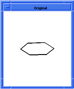  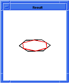
Figure. wire-body:polygon
|
[Top]
wire-body:unbranch
- Action
- Splits a branched wire body into its component branches.
Filename- scm/scmext/cstr/wire_scm.cpp
APIs- api_get_edges
Syntax- (wire-body:unbranch entity-list)
Arg Types-
Returns- entity
| (entity ...)
- Arguments
- entity-list is a list of input entities.
; wire-body:unbranch
; Create topology to demonstrate command.
(define edge1
(edge:circular
(position 0 0 0) 25 0 180))
;; edge1
; Create edge 2.
(define edge2
(edge:circular
(position 0 0 0) 25 180 270))
;; edge2
; Create edge 3.
(define edge3
(edge:linear
(position 0 0 0) (position 25 0 0)))
;; edge3
; Create a wire-body.
(define wirebody
(wire-body (list edge3 edge1 edge2)))
;; wirebody
; Display information concerning entity.
(edge:types)
; entity: (entity 16 1)
; edge:(entity 17 1)
edge_type:straight
; edge:(entity 18 1)
edge_type:circle
; edge:(entity 19 1)
edge_type:circle
;; #t
; Split wirebody.
(define split (wire-body:unbranch wirebody))
;; split
; Display information on unbranched entity.
(edge:types)
; entity: (entity 16 1)
; edge:(entity 17 1)
edge_type:straight
; edge:(entity 18 1)
edge_type:circle
; edge:(entity 19 1)
edge_type:circle
; entity: (entity 20 1)
; edge:(entity 21 1)
edge_type:straight
; edge:(entity 22 1)
edge_type:circle
; edge:(entity 23 1)
edge_type:circle
;; #t
|
[Top]
wire:reverse
- Action
- Reverses the sense of a wire.
Filename- scm/scmext/cstr/wire_scm.cpp
APIs- api_reverse_wire
Syntax- (wire:reverse wire [ao])
Arg Types-
Returns- wire
- Arguments
- wire is an input wire argument.
-
ao contains journaling and versioning information.
; wire:reverse
; Create a wire-body
(define body1
(wire-body (edge:linear (position 0 0 0)
(position 40 0 0))))
;; body1
; Get a list of wires
(define wires1 (entity:wires body1))
;; wires1
; Reverse the sense of the wire
(define reverse (wire:reverse (car wires1)))
;; reverse
|
[Top]
© 1989-2007 Spatial Corp., a Dassault Systèmes company. All rights reserved.