Scheme Extensions |
|
|
Technical Article |
Scheme is a public domain programming language, based on the LISP language, that uses an interpreter to run commands. ACIS provides extensions (written in C++) to the native Scheme language that can be used by an application to interact with ACIS through its Scheme Interpreter. The C++ source files for ACIS Scheme extensions are provided with the product. Spatial's Scheme based demonstration application, Scheme ACIS Interface Driver Extension (Scheme AIDE), also uses these Scheme extensions and the Scheme Interpreter. |
axis-start | position |
axis-end | position |
start-dir | gvector |
radius | real |
thread-distance | real |
handedness | boolean |
ao | acis-options |
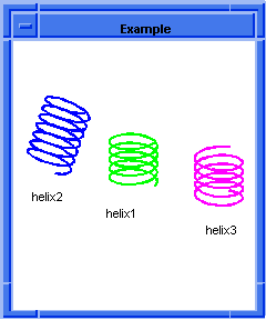
; edge:helix ; Create a helical edge. (define axis-start1 (position 0 0 0)) ;; axis-start1 (define axis-end1 (position 0 0 10)) ;; axis-end1 (define start-dir1 (gvector 1 0 0)) ;; start-dir1 (define radius1 5) ;; radius1 (define thread-distance1 2) ;; thread-distance1 (define helix1 (edge:helix axis-start1 axis-end1 start-dir1 radius1 thread-distance1)) ;; helix1 ; Create another helical edge. (define helix2 (edge:helix (position -20 0 0) (position -20 10 10) (gvector 0 1 0) 5 2 #f)) ;; helix2 ; And one more. (define helix3 (edge:helix (position 20 0 0) (position 20 0 10) (gvector 0 1 0) 5 2 #f)) ;; helix3 ; OUTPUT Example Figure. edge:helix |
[Top]
face | face |
distance | real |
apply-transform | boolean |
ao | acis-options |
Description
This extension creates a new face that is offset a specified distance from a
given face.
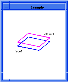
; face:offset ; Create a face. (define face1 (face:plane (position 0 0 0) 30 30)) ;; face1 ; Create a face offset. (define offset1 (face:offset face1 5)) ;; offset1 ; OUTPUT Example Figure. face:offset |
[Top]
base_wire | wire |
offset_options | wire_offset_options |
ao | acis-options |
Description
This command performs an offset operation to the given base wire with the
parameters specified by the given wire offset options.
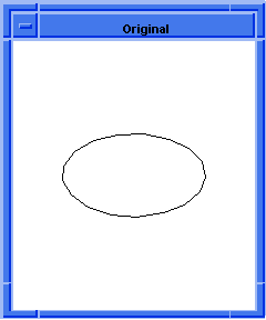
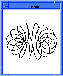
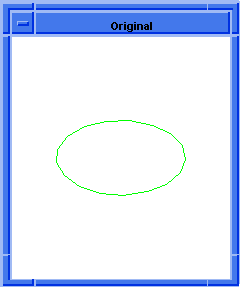
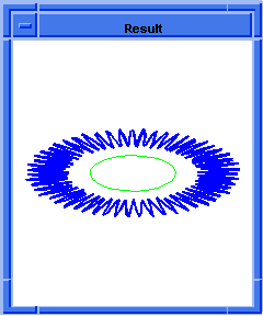
; wire-body:offset ; Create a wire-body by offsetting a wire by ; a given distance. ; Create edge 1. (define edge1 (edge:circular (position 10 0 0) 10)) ;; edge1 ; Create a wire-body from the edges. (define wirebody1 (wire-body (list edge1))) ;; wirebody1 ; OUTPUT Original ; Offset a wire-body outside the original wire-body. (define offset (wire-body:offset wirebody1 5 "2*x")) ;; offset ; OUTPUT Result Figure. wire-body:offset ; Another example using laws.(part:clear) ;; #t (define edge1 (edge:circular (position 0 0 0) 20)) ;; edge1 ; OUTPUT Original (define wirebody2 (wire-body edge1)) ;; wirebody2 (define offset1 (wire-body:offset wirebody2 "20+10*cos(x*10)")) ;; offset1 ; OUTPUT Result Figure. wire-body:offset - Using Laws to Define Geometry |
[Top]
wire | wire |
offset-distance | real |
direction | par-pos | gvector |
ao | acis-options |
Description
The function expects a body containing at least one independent wire that is
not connected to any faces. If the body contains multiple independent wires,
each independent wire in the body will be offset and united with the offsets of
the others.
This function offsets a single wire of a multi-wire body.
; wire-body:offset1 (define e1(edge:linear (position 0 0 0) (position 10 0 0))) (define e2(edge:linear (position 10 0 0) (position 20 0 0))) (define WB(wire-body (list e1 e2))) (define x-vec(gvector 0 1 0)) (define offset1 (wire-body:offset1 WB 5 x-vec)) |
[Top]
wire | wire |
offset-distance | real |
transf | transform |
direction | par-pos | gvector |
ao | acis-options |
Description
The function expects a body containing at least one independent wire that is
not connected to any faces. If the body contains multiple independent wires,
each independent wire in the body will be offset and united with the offsets of
the others.
This function offsets a single wire of a multi-wire body.
; wire-body:offset2 (define e1(edge:linear (position 0 0 0) (position 10 0 0))) (define e2(edge:linear (position 10 0 0) (position 0 10 0))) (define WB(wire-body (list e1 e2))) (define x-vec(gvector 0 1 0)) (define offset1 (wire-body:offset2 WB 5 (transform:rotation (position 0 0 0) (gvector -3 0 0) 45) x-vec)) |
[Top]
name-of-option | string |
value | string | law | real | gvector |
options | wire_offset_options |
gap_type
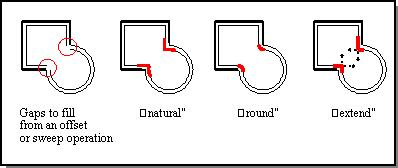
specifies the type of gap to be placed when the offsets of adjacent,
non-tangential wire edges do not touch at a common vertex. The type can be "n",
"r", or "e" ("N", "R", "E"), which represents natural, arc, or linear gap fill,
respectively. Presently, the gap type "natural" might be done with a linear
extension if curvature extension cannot be achieved. Also the gap types
"linear" and "natural" might be done with an "arc" extension if the gap cannot
be filled by the intersection of the two extended neighboring offset curve
segments. A warning is issued if the gap_type is changed.
distance
can be either a double value or a law, which specifies the offset distance.
trim
is a Boolean value to indicate if self intersections are to be removed. Default
value is true.
overlap
is a Boolean value to indicate if overlapping segments are to be removed.
Default value is true.
keep_minimum_topology
is a Boolean value to indicate if additional edges are allowed in a gap fill.
Currently when filling a gap linearly or with an arc, additional edges are
added at the gap. If keep_minimum_topology is true, the additional gap fill
edges will not be added. If this leads to an unconnected offset curve, an error
will be issued. Default value is false.
plane_normal
is the option that specifies the normal vector of the wire plane, which is the
plane where the wire body lies. Because wire offset is a 2D offset, the wire
body must lie on a plane. Default value is computed plane normal by an ACIS
internal function.
twist_law
specifies whether to use the twist law. Default value is no law (that is, no
twist); thus, the offset curve becomes simply a function of the given
offset-distance-law at the curve parameter x. In such a case and if the
offset-distance-law is a constant, the unitized cross product T x N specifies
the positive direction for the offset. If the twist-law is specified, the given
equation determines where the offset curve at curve parameter x lies in three
dimensional space. Twisting is about the tangent vector T of the wire curve and
in the plane created by T x N and N. The twist-law specifies the angle in the
TxN and N plane for the offset curve. (The twist-law evaluates to a number that
is input as radians to the cos and sin law functions.) For example, if the
offset-distance-law is the constant 2 and the twist-law is simply the law
function "x", then the result is a helix of radius 2 that winds around wire.
Note: All the options are optional, except distance,
which must be specified for a successful wire offsetting operation. If an
option is not specified, the default one is used.
(define wopts (wire-offset:options "distance" -2)) (define wopts (wire-offset:options "distance" -2 "gap_type" "N" "trim" #t "wire_normal" (gvector 0 0 -1))) (define wopts (wire-offset:options "distance" "x/4 + 20" "twist_law" "x")) |
[Top]
© 1989-2007 Spatial Corp., a Dassault Systèmes company. All rights reserved.