
| |
Thickening |
| <<< Hollowing | Chapters | Introduction To Model Editing >>> |
Thickening is the process of offsetting all the faces in a sheet body in order to create a solid body. Parasolid provides thickening functionality so that you can model thin-walled parts, for example sheet metal parts, in your application.
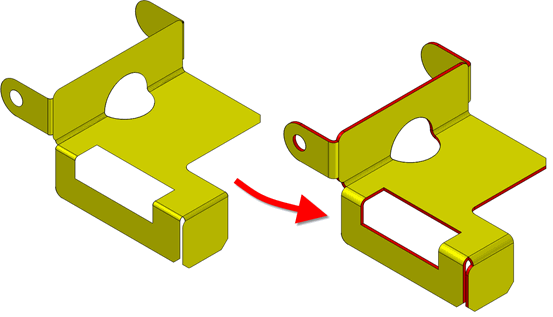
Figure 60-1 Thickening a sheet body into a solid body
Sheets may be thickened from either or both sides, along the surface normal. All faces in the sheet body can be thickened by the same amount, or different distances can be specified for different faces. Only manifold sheets can be thickened.
Side faces are created during thickening using one of the following methods:
In the first two of these methods, analytic geometry is used where possible, and ruled B-surfaces are used otherwise. Some edge geometry on the sheet boundary may have to be approximated by SP-curves in order to generate boundary curves on the offset faces.
Parasolid’s offsetting functionality is fundamental to the thickening operation. This means that certain topological changes are possible when thickening, such as deleting faces that become degenerate by offsetting. Figure 60-2 shows an example.
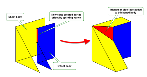
Figure 60-2 Thickening a sheet body, resulting in a topological change
By default, Parasolid creates triangular side faces when thickening sheets with sharp internal (i.e. non-boundary) edges, such that the two faces adjacent to the edge do not meet smoothly.
In general, the changes to topology and geometry that are permitted during thickening operations are similar to those permitted for offsetting operations. See Section 58.11, “Changes to topology and geometry”, for more details.
Thickening fails on valid sheet bodies that have a point contact vertex, such as the example shown in Figure 60-3. Thickening this sheet body would create an invalid solid body that contains a non-manifold edge.
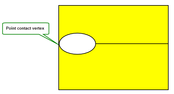
Figure 60-3 Thickening a sheet body with a point contact vertex
|
Note: This functionality offers partial support for facet geometry. |
You can thicken a sheet body to form a solid body using PK_BODY_thicken_3. This function receives a
body
, together with offset information which it uses to generate the appropriate thickened body.
Unlike offsetting and hollowing, where a single offset distance is specified, PK_BODY_thicken_3 receives two offsets:
front_default
and
back_default
. The sheet body is then thickened by offsetting in both directions by the specified amount, as shown in
Figure 60-4.
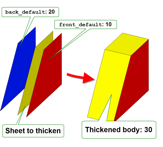
Figure 60-4 Thickening a body using front and back offsets
Under some circumstances it may be necessary to replace exact edge geometry with tolerant geometry. Parasolid uses the supplied
tolerance
when calculating approximate geometry.
The following table provides a summary of the options available in PK_BODY_thicken_3. Default values are set such that all faces in the sheet body are thickened by the amount specified in the arguments to PK_BODY_thicken_3.
|
A group of options that are used to specify that certain faces in the body should be thickened by different amounts than those specified in the |
|
|
|
Options that allow you to thicken a body in a direction other than the direction of the surface normals of the body’s faces. See Section 60.4, “Specifying a punch direction for side faces” for details. |
edges n_edges surfaces n_surfaces |
Options to let you supply side surfaces to use for certain areas of the thickened body, rather than allowing Parasolid to generate those surfaces automatically. See Section 60.5, “Supplying side surfaces to use when thickening”, for more details. |
|
The method by which self-intersections are removed when thickening. This is the same option as available in Parasolid’s offsetting functionality. See Section 60.6, “Dealing with self-intersecting surfaces” for more details. |
report_sx |
Whether to report such self-intersections in the Parasolid report. See Section 60.6, “Dealing with self-intersecting surfaces”. Also available in all hollowing and offsetting operations. |
fix_degens report_fix_degens |
Whether to fix degeneracies in the input body before the thicken operation. Whether to report such degeneracies in the Parasolid report. See Section 58.4, “Dealing with degenerate faces”, for more details. Also available in all hollowing and offsetting operations. |
blend_edges blend_radius |
Whether to produce blend faces when offsetting edges, together with the radius of the blend faces to produce. See Section 60.7, “Creating blends from offset edges”. |
ortho_vx_split |
Whether to split laminar vertices orthogonally to surface geometry during the offset part of the thicken operation, so as to avoid triangular side faces. See Section 60.8, “Controlling triangular side faces”. |
n_pierce_faces pierce_faces |
An array of faces that are removed from the thickened body, rather than being offset. This may result in a disjoint solid body. See Section 60.9, “Piercing faces”. |
offset_step |
Whether to create side faces along smooth edges that are affected by the thicken operation. See Section 60.10, “Step faces along smooth edges”. |
grow |
How to heal models when features of different convexity overflow each other. See Section 60.11, “Controlling the growth of overflowing faces”. Also available in all hollowing and offsetting operations. |
update |
Update switch to maintain consistency when rebuilding models built in older versions of Parasolid. See Section 62.5.2, “Update control”, for information. Default: PK_local_ops_update_default_c. |
By default, PK_BODY_thicken_3 thickens a body by offsetting all the faces in the body by the specified
front_default
and
back_default
. If you wish, you can specify that certain faces in the body are offset by different distances, by supplying alternative offsets for those faces. You do this using the following options:
By default, side faces are created in the direction of the surface normals. You can thicken faces in a different direction using the
method
and
punch_dir
options. To use these options:
method
to PK_thicken_method_punch_c.
punch_dir
.Parasolid then creates side faces in the punch_dir direction instead of the direction of the surface normals, as shown in Figure 60-5. Alternatively, side faces can be generated based on side surfaces you supply yourself, as described in Section 60.5, “Supplying side surfaces to use when thickening”.
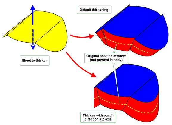
Figure 60-5 Specifying a punch direction for side faces
Instead of letting Parasolid generate side surfaces, you can use the
edges
and
surfaces
options to supply your own, in order to influence the final appearance of the thickened body. To supply side surfaces, you either:
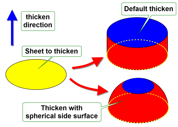
Figure 60-6 Specifying side surfaces to use during thicken operations
If you specify a single side surface, then
n_surfaces
should be 1, and
edges
and
n_edges
should be left at their default values. If you supply several side surfaces, then
n_surfaces
and
n_edges
must have the same value. The first side surface supplied in
surfaces
is then used on the first edge supplied in
edges
, the second side surface is used on the second edge, and so on.
|
Note: In all cases, each of the laminar edges must lie on the supplied side surface that is used for that edge when thickening. |
If
n_surfaces
is 0 (the default), then edges and surfaces are ignored. Parasolid generates new side surfaces for every laminar edge in the body according to the value of the
method
option and, if relevant, the specified
punch_dir
.
Sometimes, thickening a sheet may create self-intersecting surfaces on either the side face, or the offset face itself. These can be repaired, as follows:

Figure 60-7 Replacing self-intersecting side surfaces during thickening
offset_method
is set to PK_offset_method_sx_repair_2_c. See
Figure 60-8.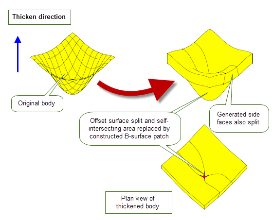
Figure 60-8 Replacing self-intersecting offset surfaces during thickening
See Section 58.3, “Removing self-intersections”, for information about removal of self-intersections in offsetting and hollowing.
When you thicken a body, you can optionally choose to round off the edges of the body that are offset during the thicken operation.
To do this, you can use the
blend_edges
and
blend_radius
options available in PK_BODY_thicken_3, which let you replace offset edges in a hollowed body with constant-radius rolling-ball blends.
You use these options in the same way as the identical options available in offsetting operations, and they are subject to the same constraints. See Section 58.8, “Creating blends from offset edges”, for more information.
Figure 60-9 illustrates the configurations in which edges are offset to blend faces.
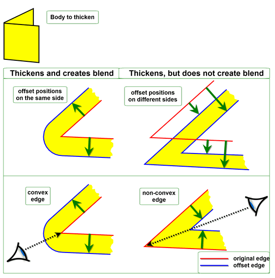
Figure 60-9 Constraints for replacing offset edges with blends
An example of this functionality is illustrated in Figure 60-10.
In cases where three or more edge-derived blends meet at a common vertex, a blend is derived from that vertex, as shown in Figure 60-10. Except for the face indicated in this example, each face in the sheet body is offset by a value equal to the specified blend radius.
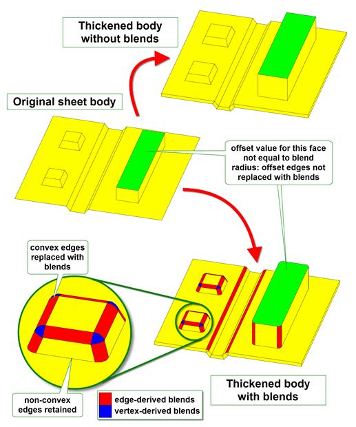
Figure 60-10 Creating blends from offset edges and vertices
Blends can be created from offset edges in all hollowing and thickening operations. The
blend_edges
and
blend_radius
options are available in the following options structures:
Note: The
blend_edges
value PK_EDGE_offset_blend_convex_c is not supported for mixed edges. |
Sometimes, a laminar vertex needs to be split during a thicken operation. By default, the new vertex is trimmed back to the laminar edge, leading to a triangular face in the resulting thickened body. However, it is sometimes preferable to produce a thickened body that contains no triangular faces, as shown in
Figure 60-11. You can achieve this effect in many cases by setting the
ortho_vx_split
option to PK_LOGICAL_true. This option ensures that any appropriate vertices are split orthogonally to the face of the other laminar edge, often eliminating the need to create a triangular face.
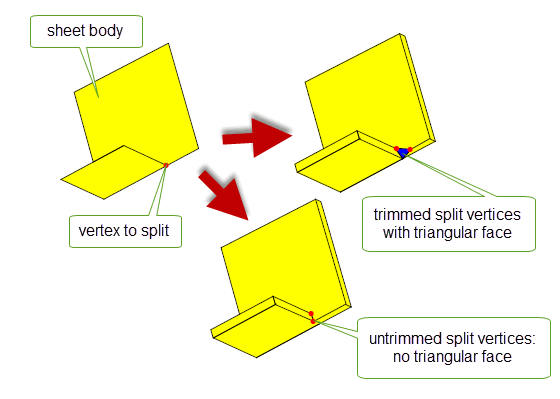
Figure 60-11 Controlling triangular side faces during thickening
Similar control is available for Parasolid’s offsetting functionality: see Section n, “PK_FACE_offset_o_t”.
Sometimes, you might want to designate that some faces in the thickened body should be treated as pierce faces, similar to the pierce faces used in hollow operations (described in Section 59.3). If you specify one or more pierce faces in a thicken operation, then those faces are removed from the resulting thickened body, rather than being thickened themselves. This is equivalent to specifying that some faces should be offset by zero.
You specify pierce faces for thickening using the
n_pierce_faces
and
pierce_faces
options.
In Figure 60-12, two faces of the original sheet have been pierced during the thickening operation.

Figure 60-12 Two faces pierced
|
Note: Using this option may result in a disjoint body. Unlike offsetting, thickening does not contain a specific option to control whether disjoint bodies should be created or not. |
When you thicken the faces in a body by different amounts, you can sometimes get undesirable results if the body contains faces that are joined smoothly. You can address this problem by requesting that Parasolid creates side faces between any smoothly joined faces that are thickened by different amounts.
The
offset_step
option determines whether side faces (or step faces) are created when offsetting a face that is joined smoothly to its neighboring faces. This option takes the following values:
In general, you should use PK_offset_step_all_c if you want to create side faces.
Figure 60-13 shows the behaviour when two smoothly-joined faces are thickened using different front offset distances for each face.
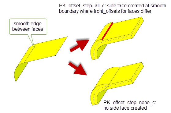
Figure 60-13 Step faces created between faces with different offset distances
Figure 60-14 illustrates the use of
offset_step
in conjunction with
n_pierce_faces
and
pierce_faces
; the same operation is shown from two different angles. The pierced face is smoothly connected to its neighboring faces and
offset_step
has been set to PK_offset_step_all_c. As a result, four step faces are created, corresponding to the front and back offsets of each common edge.
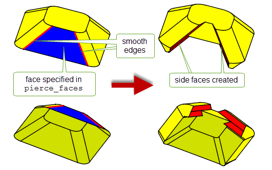
Figure 60-14 Side faces created at smooth joins both front and back
|
Note: Creating step faces at smooth edges splits the end vertices of those edges. You can supply a maximum of two different thicken distances (including zero) for the faces that share that vertex. |
When features with different convexities overflow each other as a result of thickening, you can control which of the clashing features is grown to heal the model using the
grow
option.
Figure 60-15 shows a simple example of the effects that you can achieve using this functionality.

Figure 60-15 Controlling the growth of overflowing features with different convexity
This option is available in a range of different functional areas, including local operations, hollowing, and thickening. For a full description, see Section 72.5.5, “Controlling the growth of overflowing faces”.
| <<< Hollowing | Chapters | Introduction To Model Editing >>> |