
 |
Offsetting |
| <<< Introduction To Offsetting Operations | Chapters | Hollowing >>> |
Offsetting, hollowing and thickening are related modeling operations in common use in CAD/CAM systems.
These operations are used to model, for example, objects for injection molding or casting, or thin walled aerodynamic parts.
Parasolid provides interfaces that let you hollow and thicken bodies in one function call; Parasolid offsets all the required faces by the specified distance automatically, rather than requiring you to specify each offset face individually. However, in addition, you have direct access to the offsetting functionality that is fundamental to hollowing and thickening operations, for your own purposes. Figure 58-1 shows a simple example in which a chain of faces have been offset in a body in order to create a new set of faces.
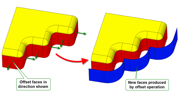
Figure 58-1 Offsetting faces in a body
This chapter describes the offsetting functionality that is available.
|
Note: This functionality offers partial support for facet geometry. |
For examples of these functionalities, see the code examples in the
C++\Code Examples\Modelling\LOP\Hollow
Offset
Thicken
folder, located in
example_applications
in your Parasolid installation folder.
You can offset all of the faces in a body by using PK_BODY_offset_2. This function receives a
body
and offsets all the faces in that body by the specified
offset
. The offset distance can be positive or negative:
You can optionally choose to offset a subset of those faces by different distances (including zero) by specifying the
offset_faces
and
offset_values
options.
Alternatively, you can offset a specific set of faces in a body using PK_FACE_offset_2. This function receives a set of
faces
, together with a set of
offsets
, and offsets each face by the corresponding offset.
Both functions allow you to further control the resulting offset body using the following options:
|
Note: Most of these options are also available for hollowing and/or thickening operations. This is indicated throughout the rest of this chapter as appropriate. |
allow_disjoint |
Whether to allow the creation of disjoint bodies as part of the operation. Setting this to PK_LOGICAL_true can sometimes produce results that might otherwise fail or give an undesired result. |
check_fa_fa |
Whether to check for face-face inconsistencies. Also available in all hollowing and thickening operations. |
offset_method |
Which method to use when removing self-intersections in the resulting body. See Section 58.3, “Removing self-intersections”. Also available in all hollowing and thickening operations. |
report_sx |
Whether to report such self-intersections in the Parasolid report. See Section 58.3, “Removing self-intersections”. Also available in all hollowing and thickening operations. |
offset_step |
Whether to create side faces, or step faces, in the resulting body. See Section 58.5, “Creating offset steps”. Also available in all hollowing and thickening operations. |
ortho_vx_split |
How to split laminar vertices when offsetting. See Section n, “PK_FACE_offset_o_t”. Also available in thickening operations. |
track_del |
Whether to track partially tightly-curved faces that are deleted when offsetting. See Section 58.7, “Tracking the deletion of partially tight-curved faces”. |
|
Whether to fix degeneracies in the input body prior to offsetting. Whether to report such degeneracies in the Parasolid report. See Section 58.4, “Dealing with degenerate faces”. Also available in all hollowing and thickening operations. |
blend_edges blend_radius |
Whether to create blend faces from edges that are offset, and the radius to use for those blend faces. See Section 58.8, “Creating blends from offset edges” |
grow |
How to heal models when features of different convexity overflow each other. See Section 58.9, “Controlling the growth of overflowing faces”. Also available in all hollowing and thickening operations. |
vertex_limit edge_limit |
How to constrain the maximum tolerance used by each vertex or edge, as appropriate. See Section 58.10, “Constraining edge and vertex tolerance when offsetting”. |
update |
Update switch to maintain consistency when rebuilding models built in older versions of Parasolid. See Section 62.5.2, “Update control”, for information. Default: PK_local_ops_update_default_c. |
Parasolid provides two offset functions, one that operates on an entire body, and one that operates on specific faces within a body. Both functions provide identical options, including the ability to offset different faces by different amounts, or to choose not to offset a given face at all. So which function should you choose?
These two functions use the same underlying functionality. Both are provided by Parasolid to provide the flexibilty to customise your usage of these in your application as much as possible. For example there are situations where it might be advantageous to use one or the other in your application code.
Ultimately, there is no preferred method. Both functions are provided by Parasolid to ensure that you have as much choice as possible.
Creating accurate offset surfaces can sometimes introduce self-intersections which can cause problems with the associated offset, hollow, or thicken operation. Parasolid can remove such self-intersections, and heal any resulting holes. If
report_sx
is set to PK_LOGICAL_true, information regarding the faces that have been repaired to remove self-intersections is saved in the Parasolid report. See Chapter 11, “Using Reports”, for more information about the Parasolid report mechanism.
Faces whose offsets are completely self-intersecting are healed by intersecting neighboring surfaces.
Faces whose offsets are partially self-intersecting are healed using one of the following methods:
These solutions are illustrated in Figure 58-2.
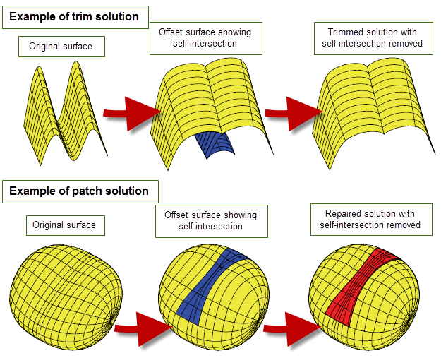
Figure 58-2 Removing self-intersections during offsetting operations
You can control which method is used to remove self-intersections using the
offset_method
option, which can take the following values:
The
offset_method
field is available in the following options structures:
|
Note: For offsetting and hollowing facet geometry the method for repairing self-intersections is ignored, because self-intersections are automatically repaired or removed. |
When you offset a body, you can optionally choose to repair any degeneracies on the surfaces
of the body, using the
fix_degens
option. This takes the following values:
In addition, if
report_fix_degens
is set to PK_LOGICAL_true, then information about any repairs that have been carried out is saved in the Parasolid report. Each individual repair is saved as a record of
type
PK_REPORT_record_type_1_c, and contains the following information:
status |
This has the value PK_REPORT_1_fa_fix_degens_c if degeneracies have been fixed. |
old_items |
Original faces that were repaired, followed by the original surface. In the case where the original surface was an offset surface, this is followed by the underlying B-surface. |
new_items |
The repaired B-surface, followed by the corresponding offset surfaces, followed by the corresponding faces on the resultant offset body. |
No reports of this type are returned if
fix_degens
is left at its default value, or if no surfaces were repaired during the operation.
The default value of
report_fix_degens
is PK_LOGICAL_false.
See Chapter 11, “Using Reports”, for more information about the Parasolid report mechanism.
In some cases, offsetting faces in a body requires the creation of additional side faces perpendicular to the faces being offset, as shown in Figure 58-3. This may be necessary either to improve the appearance of the final model, or to successfully offset the faces at all.
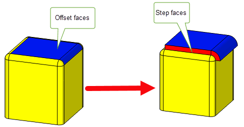
Figure 58-3 Creating step faces during offsetting
Such side faces are known as offset steps, and they can be created whenever the boundary edge (i.e. the edge between a face being offset and a face that is not offset) is smooth, as shown in Figure 58-4.
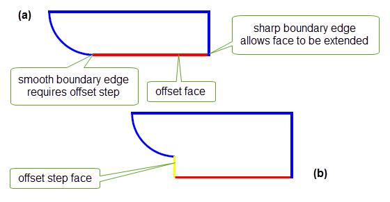
Figure 58-4 Cross-section of body (a) before and (b) after offsetting using an offset step face
You can create offset steps using the
offset_step
option, which takes the following values:
|
Note: Creating step faces at smooth edges splits the end vertices of those edges. You can supply a maximum of two different offset distances (including zero) for the faces that share that vertex. |
The
offset_step
option offers similar behaviour to the
transform_step
option in PK_FACE_change. See Section 72.4.3.2, “Creating step faces when performing rotations or translations”, for more information.
Offset steps can be created in all hollowing and thickening operations. The
offset_step
field is available in the following options structures:
If a laminar vertex needs to be split during an offset operation, you can control whether the split vertex is trimmed back to the laminar edge, or whether the vertex is split orthogonally to the face of the other laminar edge. This can lead to different results in the offset body, as shown in Figure 58-5.
To split appropriate vertices orthogonally to the surrounding geometry, set the
ortho_vx_split
option to PK_LOGICAL_true.
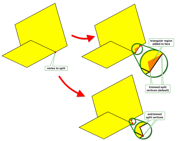
Figure 58-5 Controlling how offset faces are trimmed
As well as offsetting, you can control trimming during thicken operations. The
ortho_vx_split
option is available for the following functions:
See Section 60.8, “Controlling triangular side faces”, for details on using this functionality with thickening operations.
When you offset tightly curved faces in a body , they are liable to be deleted: for instance, if you offset a blend face by a distance greater than the blend radius, it will be deleted from the resulting body. For faces that are entirely tightly curved, users of your application will probably expect this behaviour. However, the same behaviour is true of faces that are only partially tightly-curved, and your users may not expect this.
To help mitigate against any undesired results you can choose to track any partially tightly-curved faces that are deleted during offset operations. Doing this makes it easy for your application to identify partially tightly-curved faces when rolling back after an offset operation.
To track partially tightly-curved faces, set
track_del
to PK_offset_track_del_sx_repair_c. Any faces that are removed from the offset body because they contain tightly-curved regions have a record in the
track_records
returned by the offset operation, and the
track
field of that record is set to PK_TOPOL_track_delete_c.
Note: Faces that are removed from the offset body because they are entirely tightly-curved do not have corresponding track records, even when
track_del
is PK_offset_track_del_sx_repair_c. |
The
track_del
option is available in the following options structures:
When you offset faces in a body, you can optionally choose to round off the edges between adjacent offset faces during the offset operation.
To do this, offsetting operations provide the
blend_edges
and
blend_radius
options to let you replace edges between adjacent offset faces in a body with constant-radius rolling-ball blends. To use this functionality, set
blend_edges
to PK_EDGE_offset_blend_convex_c and specify a suitable
blend_radius
value.
When you perform an offset, edges are replaced by blends of the specified radius, subject to the following constraints:
blend_radius
.Any offset edges in the body that do not satisfy these constraints are offset as normal, and no blend is created.
Figure 58-6 illustrates the second and third of these constraints.
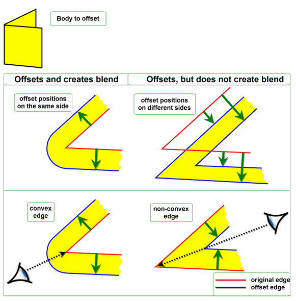
Figure 58-6 Constraints for replacing offset edges with blends
An example of this functionality is shown in Figure 58-7.
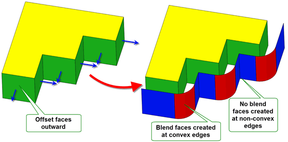
Figure 58-7 Creating blends from offset edges
Blends can be created from offset edges in all hollowing and thickening operations. The
blend_edges
and
blend_radius
options are available in the following options structures:
Note: The
blend_edges
value PK_EDGE_offset_blend_convex_c is not supported for mixed edges. |
When features with different convexities overflow each other as a result of offsetting, you can control which of the clashing features is grown to heal the model using the
grow
option.
Figure 58-8 shows a simple example of the effects that you can achieve using this functionality.
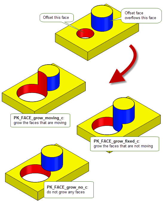
Figure 58-8 Controlling the growth of overflowing features with different convexity
This option is available in a range of different functional areas, including local operations, hollowing, and thickening. For a full description, see Section 72.5.5, “Controlling the growth of overflowing faces”.
Offsetting operations can sometimes produce large tolerances on vertices or edges that exceed both the tolerance specified for the operation and the original model tolerances. You can use the
vertex_limit
and
edge_limit
options to control whether or not to allow these large tolerances.
These options take values as shown in the table below. Note that
vertex_limit
takes values of the form PK_VERTEX_limit and
edge_limit
takes values of the form PK_EDGE_limit, though the meanings are similar for each option.
|
Do not limit the tolerance applied to vertices or edges during offset operations. This is the default, but may sometimes result in undesirably large tolerances in the result. |
|
|
Allow any tolerance to be applied to vertices or edges. In addition, record any vertices or edges for which a large tolerance has been set via the reporting mechanism, as follows:
See Chapter 11, “Using Reports”, for more information about the Parasolid reporting mechanism. |
|
|
Limit the vertex or edge tolerances set by Parasolid and fail the offset operation if these limits are not satisfied. Note: In cases where both PK_EDGE_limit_yes_c and PK_VERTEX_limit_yes_c are set, if the operation fails, then the local status returned is PK_local_status_ed_large_tol_c, even if the operation has also failed due to a vertex tolerance that does not satisfy the limits. |
Parasolid does not allow total freedom of topology changes during offsetting operations, but does support a wide spectrum of permissible changes. These were discussed in Section 62.4, “Topology changes”.
When the faces to be offset are from a sheet body, it is possible that a tolerant body is produced from the original exact body, because some edge geometry at the boundary has to be approximated by SP-curves in order to generate the boundary curve. To solve this case, Parasolid approximates the bounding edges with SP-curves to a tolerance that is less than or equal to the tolerance supplied by your application.
Figure 58-9 illustrates a case of offsetting two faces whose underlying geometry is free-form. In this example Parasolid created new edge geometry where the offset surfaces intersected. For outward offsets (positive) this can mean extending the underlying surface(s) so that the offset surfaces meet, as shown.
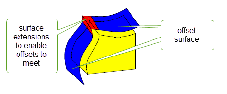
Figure 58-9 Offset surfaces extended
You can use PK_EDGE_offset_on_body to offset any set of connected edges in a given direction within their owning body. Edges can either be on a manifold body or on a general body so long as the edge to be offset lies in a locally manifold part of the body. Figure 58-10 shows an example of this.
If the offset operation encounters a non-manifold edge or vertex, the operation will fail with a status of PK_offset_on_body_general_c which lists the non-manifold edges or vertices blocking the operation.
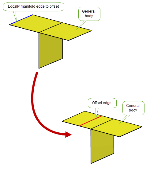
Figure 58-10 Offsetting an edge on a locally manifold general body
You can offset both laminar and non-laminar edges, and the resulting offset edges are imprinted on the body. If edges are offset so that they all lie beyond any of the faces in the body, then no edges are imprinted, and a suitable status value is returned. Laminar edges cannot be offset away from the body.
Each point on an edge is offset within its normal plane, and the offset distance is measured by arc-length along the intersection between the body’s faces and this normal plane. The offset can cross sharp edges on the body, and can cope with properties such as holes on the owning body. Figure 58-11 shows an example where a set of three edges have been offset on a sheet body that contains a hole and a sharp edge, such that the resulting set of four offset edges crosses both the sharp edge and the hole.
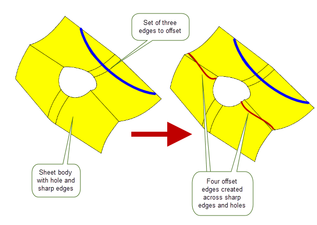
Figure 58-11 Offsetting edges in a body
For examples of this functionality, see the code example in the
C++\Code Examples\Modelling\Offset
Surface
folder, located in
example_applications
in your Parasolid installation folder.
If the offset operation results in gaps between the resultant edges, you can use either the
gap_fill
option or the
constrained_gap_fill
option to fill these gaps. Both these options share the following values:
|
Fill the gap between the offset curves with a round arc.This is illustrated in Figure 58-12. The offset edges are shown in red and the round arcs filling the gap are shown in black. |
|
|
Fill the gap between the offset curves with a tangent extension. This is illustrated in Figure 58-12. The offset edges are shown in red and the tangent extension edges are shown in black. |
|
|
Fill the gap between the offset curves with a natural curve extension as illustrated in Figure 58-13. |
You control which of these options to use with the
gap_fill_angle
option. This option takes a double constraint that defines an angular interval in radians
gap_fill
option is used. 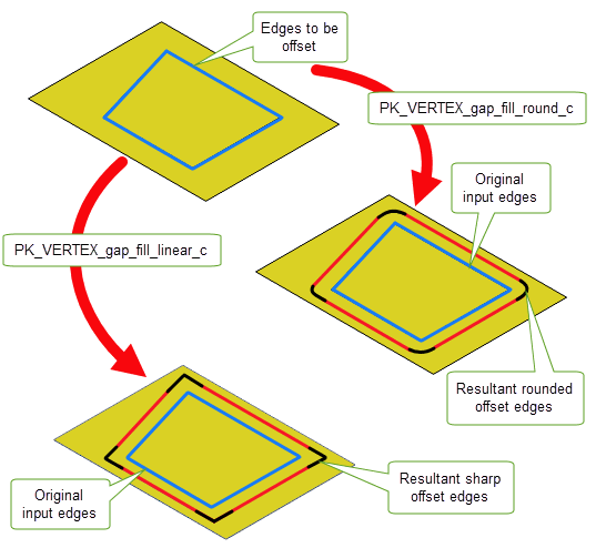
Figure 58-12 Offsetting non-g1 edges and filling the gaps between the resultant edges using the PK_VERTEX_gap_fill_round_c and PK_VERTEX_gap_fill_linear_c values of the
gap_fill
option
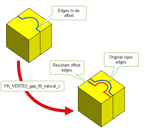
Figure 58-13 Offsetting non-g1 edges and filling the gaps between the resultant edges with the
gap_fill
option set to PK_VERTEX_gap_fill_natural_c.
If your application relies on reproducing behaviour when updating models built using earlier versions of Parasolid, you should use the
update
option in PK_EDGE_offset_on_body to preserve old behaviour and help eliminate differences in rebuild results. This option lets you disable some offsetting enhancements that have been added at different Parasolid versions. Doing this ensures that offsetting gives the same results in the latest version of Parasolid as in earlier versions. See PK_local_ops_update_t in the
PK Interface Programming Reference Manual for more information on this
update
option.
|
Note: The default value is PK_local_ops_update_default_c which uses all appropriate offsetting enhancements. Setting to a non-default value disables all appropriate offsetting enhancements. See Chapter 118, “Update Switches”, for more information on update switches. |
| <<< Introduction To Offsetting Operations | Chapters | Hollowing >>> |