
| |
Controlling Redundant Topology |
| <<< Euler Operations | Chapters | Splitting Topology >>> |
Bodies may sometimes contain edges or vertices that are not required for a complete, valid definition of the model. Such topology is referred to as redundant topology, and may include:
Parasolid provides you with functions to delete redundant topologies such as these from a body, or to identify them in order to take some other action (for example, to attach attributes to anything your application does not consider redundant). Dealing with redundant topology is often required before exporting data to another application. Figure 33-1 shows some simple examples of redundant topology on a body.
You can use the following functions to manage redundant topology in a body:
|
Identify and then delete redundant topology from a model, merging together entities that become mergeable as a result of the deletion. See Section 33.2, “Deleting redundant topology”. |
|
|
Identify any topological entities in a body that are redundant. See Section 33.3, “Identifying redundant topology”. |
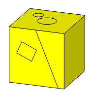
Figure 33-1 Redundant topology in a body
PK_TOPOL_delete_redundant_2 receives an array of
topols
together with a set of options. It deletes any topologies that are found to be redundant, and merges remaining topologies that become mergable as a result of this action. You can control the behaviour of the function using the following options:
max_topol_dimension |
Lets you control which topologies are regarded as redundant, according to the dimension of the topology. For instance, to remove only redundant vertices from a body, set |
scope |
Lets you specify the scope of the operation. This lets you control how sub-topologies on the boundaries of the specified Default: PK_redundant_merge_on_c. |
facet_geom_continuity |
Determines the level of geometric continuity between adjacent facet geometries that is necessary for topology to be considered redundant. See Section 33.2.2, “Controlling redundant topologies on facet geometry” for more information. Default: PK_continuity_g0_c. |
have_vertex_angle |
Whether a |
vertex_angle |
An angle used to determine whether an mvertex between two polyline edges of a mesh will be considered for redundancy. See Section 33.2.2, “Controlling redundant topologies on facet geometry” for more information. |
n_protected_topols protected_topols |
Lets you specify any topologies that you want to ensure are not deleted during the operation. |
|
Note: The facet_geom_continuity, have_vertex_angle, and vertex_angle options can only be used with facet geometry. |
The
scope
option can be used to control the number of topologies that are deleted. This is illustrated in
Figure 33-2, which shows a sheet body comprising three faces, containing several redundant edges and vertices. In the call to PK_TOPOL_redundant_2, the two faces shown in red are supplied as
topols
. Different values of
scope
produce different results for this example, as follows:
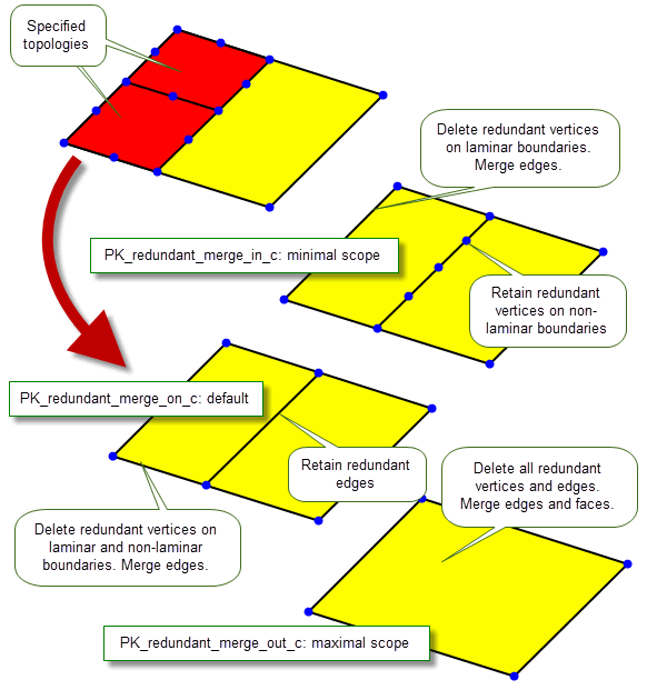
Figure 33-2 Specifying the scope when deleting redundant topologies
PK TOPOL_identify_redundant and PK TOPOL delete redundant 2 can be also be used to optimise redundant topology on facet bodies, but you are recommended to change the default settings of
facet_geom_continuity
,
have_vertex_angle
, and
vertex_angle
options to achieve the best results. Failure to do this can mean the removal of almost all topology from a facet body, which is not desirable as it can have a detrimental impact on the performance of subsequent modelling operations.
The
facet_geom_continuity
option controls the degree of continuity between adjacent facet geometries and determines whether topology is considered redundant. It takes the following values:
|
All manifold non-laminar edges between faces with mesh surfaces or wire edges in faces with mesh surfaces are considered redundant. All manifold mvertices between or on edges with polyline curves are considered redundant unless more than two non-redundant edges meet at the mvertices. Note: When using facet bodies, this value will remove all non-laminar manifold topology from the facet body. This typically results in a single-faced body with a single mesh surface. |
|
|
Edges on a facet body are considered redundant if the mvertices lying on the edge will not become sharp when the edge is removed. A sharp mvertex is one that does not have a unique normal, i.e the mfins at this mvertex do not share the same normal as returned from PK_MFIN_ask_mvx_normal. For more information on sharp mvertices, see Section 88.3.2.3, “Finding sharp mvertices in meshes”.
An mvertex between two polyline edges is considered for redundancy if either of the polyline edges belongs to the g1 edge chain of the other. You can check this by calling PK_EDGE_find_g1_edges with its |
Note: To achieve the best results using facet geometry, we strongly advise that you set
facet_geom_continuity
to PK_continuity_g1_c,
have_vertex_angle
to PK_LOGICAL_true and
vertex_angle
to an angular tolerance of your choice. |
If you want to take some action other than deleting redundant topologies, use PK_TOPOL_identify_redundant. This function receives an array of
topols
together with a set of options. It returns those topologies that are found to be redundant.
You might, for instance, use this function to attach an attribute to all topologies found to be redundant in a body, for later processing.
PK_TOPOL_identify_redundant lets you control its behaviour using the following options, some of which are identical to those found in PK_TOPOL_delete_redundant_2:
max_topol_dimension |
The maximum dimension of topologies to be identified. See Section 33.2, “Deleting redundant topology” for details. |
scope |
The scope of the operation. See Section 33.2.1, “Controlling the topologies to be deleted” for details. |
want_redundant_topols |
Whether or not to return the redundant topologies. If PK_LOGICAL_false, then only the number of redundant topologies is returned. |
propagate_redundancy |
Whether or not to identify dependent redundant topologies, i.e. topologies that are not themselves redundant, but would become redundant if other redundant topologies were removed. In Figure 33-3, the vertex at the intersection of the redundant edges is not itself redundant, but would become so if the redundant edges were deleted.
|
facet_geom_continuity |
Degree of continuity for use with facet geometry. See Section 33.2.2, “Controlling redundant topologies on facet geometry” for more information. Default: PK_continuity_g0_c. |
have_vertex_angle |
Whether a |
vertex_angle |
Angular tolerance for use with facet geometry. See Section 33.2.2, “Controlling redundant topologies on facet geometry” for more information. |
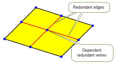
Figure 33-3 Identifying dependent redundant topologies
| <<< Euler Operations | Chapters | Splitting Topology >>> |