
 |
Identifying And Simplifying Model Details |
| <<< Deleting Entities | Chapters | Replacing The Surfaces Of Faces >>> |
Parasolid includes the following support for simplifying models:
|
Note: You can also use PK_BODY_identify_general to identify the characteristics of a body that cause it to be general. See Section 15.10, “Identifying general characteristics of a body”, for more information. |
Parasolid provides two functions that you can use to simplify the geometry in a body:
|
Note: This functionality supports models with a mixture of classic and facet geometry. However the geometry will only be simplified if it is classic. |
These functions attempt the following simplifications for the geometry shown:
These functions are particularly useful for simplifying all or part of a body after importing it into Parasolid. See Chapter 90, “Importing Data”, for more information.
You can use PK_BODY_find_facesets to find distinct sets of faces bounded by a given set of edges in a body. These facesets can then be deleted from the body, if desired, as described in Section 64.8, “Classifying model details”.
PK_BODY_find_facesets receives and returns the following arguments:
body |
|
n_edges edges |
The number of edges bounding the facesets, together with the array of edges bounding the facesets. |
options |
|
A structure containing the identified facesets, together with, optionally, the sets of edges that bound each faceset. |
The options that you can specify are as follows:
selector |
Specifies which facesets to return if one or more |
alternate |
Whether or not to return alternating facesets, starting with the supplied See Section 64.3.2, “Returning alternating facesets”, for more information. |
n_selecting_topol selecting_topol |
An array of topologies that are used to select which facesets are returned, together with the number of elements in the array. The precise facesets that are returned depends on the value of
If |
want_bounds |
Whether to return the bounding edges of each faceset. (Default: PK_LOGICAL_false) |
You can use the
selector
and
selecting_topol
options to choose exactly which facesets are returned by PK_BODY_find_facesets.
The
selector
option takes the following values:
This is illustrated in Figure 64-1.
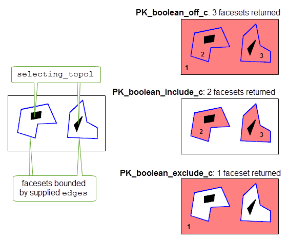
Figure 64-1 Choosing which facesets to return
If a given topology in
selecting_topol
belongs to several facesets, then they are all selected or not selected, depending on the value of
selector
.
Note: The above description applies only if
alternate
is PK_LOGICAL_false (the default). Section 64.3.2, “Returning alternating facesets”, describes the behaviour of
selector
and
selecting_topol
when alternate is PK_LOGICAL_true. |
If the
alternate
option is PK_LOGICAL_true, you can return alternate facesets in a body. The behaviour of this option depends on the value of
selector
, and requires that
selecting_topol
contains a single topological entity, which is used to identify the “root” faceset in a body from which alternating facesets are calculated.
Consider the body shown in Figure 64-2. The “root” faceset is the innermost faceset that contains the selecting topology.
selector
is PK_boolean_include_c, the “root” faceset is returned, the next outermost faceset is not returned, the next outermost faceset is returned, and so on.
selector
is PK_boolean_exclude_c, the “root” faceset is
not returned, the next outermost faceset
is returned, the next outermost faceset is not returned, and so on.
selector
is PK_boolean_off_c, all facesets are returned, regardless of the value of
alternate
.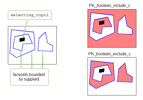
Figure 64-2 Returning alternating facesets
You can use the function PK_BODY_identify_details to identify specific types of details in a body. The function returns each detail of a specified type as a faceset, which you might then delete from the model as described in Section 64.8.
|
Note: This functionality supports models with a mixture of classic and facet geometry. However it will only identify details which are either classic holes or rubber faces. |
PK_BODY_identify_details receives and returns the following arguments:
body |
|
details n_details |
The types of detail you want to identify, together with the number of types of detail. |
options |
You should delete any redundant topology before calling this function, using PK_TOPOL_delete_redundant_2. See Section 33.1, “Introduction”, for more information.
A code example illustrating feature recognition functionality can be found in the
C++\Code Examples\Inquiries\Model Analysis\Feature Recognition
folder, located in the
example_applications
folder in your Parasolid installation folder.
The types of detail that you can identify are shown in the table. PK_BODY_identify_details returns a PK_identify_details_r_t structure that includes an array of identified
facesets
, together with an array of
details
. Each detail in the
details
array describes the type of detail represented by the corresponding faceset in the
facesets
array. The returned detail values may be any of the following:
|
A cylindrical hole with two closed ends (i.e. enclosing a cavity). |
A cylindrical hole contains at least one face with the following restrictions:
A cylindrical hole may also have additional components, so long as each component consists of an additional face with two loops and a ruled surface. Additional components make it possible to identify cylindrical holes that contain countersinks and counterbores.
Hole components are only considered to belong to the same hole if their axes are co-axial. You can use two options in PK_BODY_identify_details_o_t to control whether Parasolid considers hole components to be co-axial. Two components are considered to be co-axial:
tolerance
.
angle_tolerance
.This is illustrated in Figure 64-3.
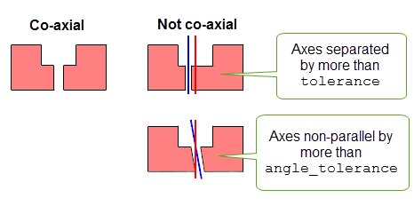
Figure 64-3 Identifying co-axial hole components (viewed in cross-section)
Cylindrical holes can be closed by any face that has a ruled surface, in particular a plane or cone. They may also be closed by a blend face, such as a face with a spherical surface.
You can use the
hole_cyl_radius
option in PK_BODY_identify_details_o_t to constrain PK_BODY_identify_details to only return cylindrical holes based on the size of the radius. See Section 64.7, “Constraining identification of details” for more information.
You can use the
hole_blended
and
hole_blend_radius
options in PK_BODY_identify_details_o_t to identify holes that include blend details. These options let you specify whether PK_BODY_identify_details should find holes that include blend faces, and to set constraints on the size of the blends in any holes that are identified.
hole_blended |
Whether to include blend faces when identifying hole details. This can take the following values:
|
hole_blend_radius |
A constraint further restricting which blend faces can be included when identifying holes. You must set this constraint if you want to identify holes that contain blends. See Section 64.7, “Constraining identification of details” for more information. |
You should use the
hole_blended
option to specify whether to include or exclude blends in holes from any cylindrical radius constraint you might have specified. For example, PK_hole_blended_in_c lets you identify all holes of a certain radius, together with any blends that might form part of the hole, regardless of the size of the blend itself.
In
Figure 64-4, if
hole_blended
is PK_hole_blended_in_c, then:
hole_cyl_radius
based on R (because R is the sum of the hole radius and the blend radius).
hole_cyl_radius
based on r.
If
hole_blended
is PK_hole_blended_out_c, then the blend faces are included in the identified hole in either case.
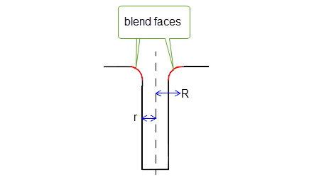
Figure 64-4 Including blends in hole radius constraints
You can find holes containing trimmed blends in addition to other blend faces by setting
hole_blended
to either PK_hole_blended_trimmed_in_c or PK_hole_blended_trimmed_out_c, as appropriate. A blend is considered to be trimmed when it does not meet at least one of its adjacent faces smoothly,.
Figure 64-5 shows a hole that includes trimmed blend components.
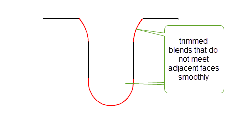
Figure 64-5 Identifying holes that include trimmed blend components
|
Note: As shown in
Figure 64-5, you can use PK_hole_blended_trimmed_in_c or PK_hole_blended_trimmed_out_c to identify blind holes with hemispherical end faces. However, such end faces do need to meet the other components of the hole smoothly. |
In cases where a hole does not enter a face at right angles, the blend spines of any associated blends are used when calculating whether the blends should be identified as part of the hole. This is shown in
Figure 64-6, where, if
hole_blended
is PK_hole_blended_in_c,
hole_cyle_radius
must be based on D/2.
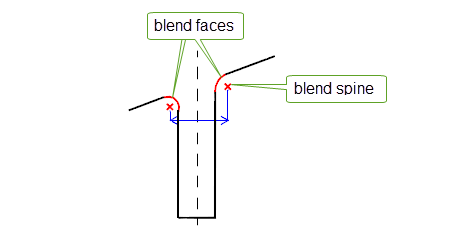
Figure 64-6 Including blends based on the blend spine
You can use the
hole_ortho
option to find only holes that can be drilled. A drillable hole is defined as a hole containing components that are either spun about the axis of the hole, or orthogonal to the hole, as shown in
Figure 64-7.
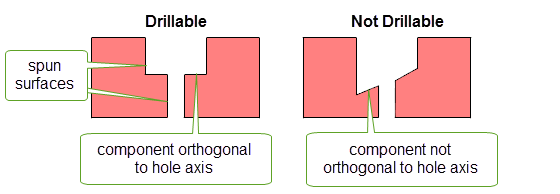
Figure 64-7 Identifying drillable holes (viewed in cross-section)
The
hole_ortho
option takes the following values:
|
Find only drillable holes. Holes that contain non-spun components that are not orthogonal to the axis are not returned. |
You can use the
angle_tolerance
option to set tolerance information to control what is considered orthogonal.
You can use the
hole_const_rad
option to find only holes that contain a constant-radius component, as shown in
Figure 64-8.
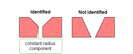
Figure 64-8 Identifying holes with constant-radius components
The
hole_const_rad
option takes the following values:
|
Find both holes that contain constant-radius components, and those that do not. (Default) |
|
|
Find only holes containing at least one constant-radius component. |
You can use the
tolerance
option to set tolerance information to control what is considered constant radius: the radii at each end of a hole component must differ by less than this value to be considered a constant-radius component.
You can use the
hole_perforated
option to also identify holes that contain perforations. A perforated hole is one which can contain inner boundaries of convex edges. Holes with perforations can be successfully identified, even if they contain redundant internal edges.
Figure 64-9 illustrates the type of perforated holes that PK_BODY_identify_details can recognise.
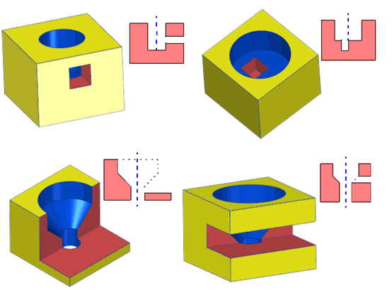
Figure 64-9 Examples of holes with perforations that can be identified
The
hole_perforated
option takes the following values:
Note: If you set
hole_perforated
to a non-default value, then
hole_ortho
must be PK_hole_ortho_yes_c. See Section 64.4.4 for details. |
You can use the
hole_open
option to also identify holes that contain open components. A hole with an open component is one where the spun faces of the hole (ignoring the end face of a blind hole) do not form a closed ring.
Figure 64-10 illustrates the type of open holes that PK_BODY_identify_details can recognise.
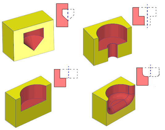
Figure 64-10 Examples of open holes that can be identified
As shown in the last example in Figure 64-10, blends can be connected to any component of an open hole, and do not need to be spun.
The
hole_open
option takes the following values:
Note: If you set
hole_open
to a non-default value, then
hole_perforated
must be PK_detail_perforated_yes_c. See Section 64.4.6 for details. |
If your application relies on reproducing behaviour when updating models created using earlier versions of Parasolid, you should use the
update
option to preserve old behaviour and help eliminate differences in rebuild results. This option lets you disable some hole identification enhancements that have been added at different Parasolid versions. Doing this ensures that hole identification gives the same results in the latest version of Parasolid as in earlier versions. See PK_hole_update_t in the
PK Interface Programming Reference Manual for more information on this
update
option.
|
Note: The default value is PK_hole_update_default_c which uses all appropriate hole identification enhancements. Setting to a non-default value disables all appropriate hole identification enhancements. |
You can use PK_FACE_identify_blends to identify blends within a body. This function lets you specify a number of constraints to control the characteristics of the blend faces that are returned.
PK_FACE_identify_blends identifies blend faces with manifold topology. The faces can be:
|
Note: This functionality partially supports the identification of mesh blends. |
PK_FACE_identify_blends receives and returns the following arguments:
n_faces faces |
The number of faces from which to search for blends, and the faces themselves. |
ident_type |
How to identify blends from the supplied |
options |
|
A return structure containing details about the blend facesets identified from the supplied |
The PK_FACE_identify_blends_o_t options structure contains the following fields:
limit_radii |
Control which blends are returned based on their radii. See Section 64.5.4, “Identifying blends based on radius” for information. Default: Return all identified blends, regardless of size. |
convexity |
Control which blends are returned based on their convexity. See Section 64.5.5, “Identifying blends based on convexity” for information. Default: Return all identified blends, regardless of convexity. |
allow_pi |
Control whether to identify blends that span pi radians. See Section 64.5.6, “Identifying blends based on span”, for information. Default: identify blends that span pi radians. |
tolerance |
A tolerance. This is used when checking the constraints specified by |
want_radii |
Whether to return the radius of each identified chain of blends. See Section 64.5.9, “Returned information” for information. Default: PK_LOGICAL_false. |
want_convexities |
Whether to return the convexity of each identified chain of blends. See Section 64.5.9, “Returned information” for information. Default: PK_LOGICAL_false. |
follow_branch |
Whether to limit propagation of blend chains at branch faces to the supplied faces. See Section 64.5.2, “Choosing how to identify blends”, for information. Default: PK_blend_follow_branch_yes_c |
propagation_angle have_propagation_angle |
Whether to propagate blend chains across sharp edges. See Section 64.5.3, “Propagating across sharp edges”, for information. Default: propagate across all sharp edges. |
optimise_chains |
Whether the blend chains are to be post-processed. See Section 64.5.10, “Optimising identified blend chains for subsequent operations”, for information. Default: PK_chain_optimise_none_c. |
update |
Update switch to maintain consistency when rebuilding models built in older versions of Parasolid. See Section 62.5.2, “Update control”, for information. Default: PK_local_ops_update_default_c. |
report_blends |
Whether to generate a Parasolid Report for blend faces that have been identified. See Section 64.5.8, “Reporting identified blend faces”, for more information. Default: PK_blend_report_blends_no_c. |
distant_unders |
Whether to identify blend faces with non-adjacent underlying faces. See Section 64.5.7, “Identifying blend faces with non-adjacent underlying faces”, for more information. Default: PK_blend_distant_unders_no_c. |
PK_FACE_identify_blends works by identifying and returning chains of connected blend faces. For each blend face in the supplied
faces
, PK_FACE_identify_blends can find other blend faces that are connected to it (whether or not they are in
faces
).
In a chain of blends, a branch face is a blend face that splits the chain into two or more branches.
You use the
ident_type
argument of PK_FACE_identify_blends to control how chains of blends are returned, with respect to the branch faces in the chain and the supplied
faces
. This can take one of the following values:
|
Only return chains of blends that are contained in the supplied |
|
|
Return a minimal chain of connected blends, excluding branch faces. This option looks for chains of blends starting from the supplied faces. If a branch face is identified outside the specified |
|
|
This is the same as PK_blend_identify_exc_chain_c, except that branch faces outside the specified faces are also included in the returned blends. |
|
|
Return a maximal chain of blends. This option makes the chains as long as possible. If a branch face is identified, it is included in the returned blend faces, and the function continues the chain of blends along each branch. |
|
|
Return chains of blends that are not within the supplied |
The difference between these values is illustrated in
Figure 64-11. Note in particular the difference between PK_blend_identify_inc_chain_c, which returns branch faces that are not in the supplied
faces
, and PK_blend_identify_exc_chain_c, which only returns branch faces if they are in the supplied
faces
.
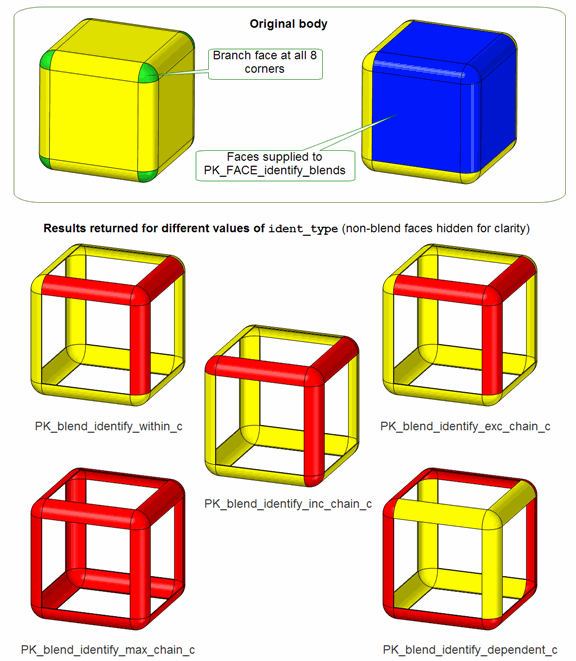
Figure 64-11 Choosing how to identify blends in the supplied set of faces
If you are returning a minimal chain of connected blends using either PK_blend_identify_inc_chain_c or PK_blend_identify_exc_chain_c, you can control the results returned even further using the
follow_branch
option. This option lets you control how the chain of blends propagates from branch faces, depending on whether or not you have supplied faces adjacent to those branch faces in the call to PK_FACE_identify_blends.
Figure 64-12 illustrates the behaviour of this option:
follow_branch
to PK_blend_follow_branch_no_c, chains are only propagated at branch faces if no faces adjacent to those branches have been supplied. If an adjacent face has been supplied (as in
Figure 64-12), then propagation at the branch face is limited to the faces supplied to PK_FACE_identify_blends.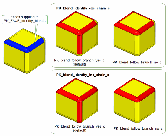
Figure 64-12 Choosing whether to follow branches when returning a minimal chain of connected blends
By default, blend chains propagate across any sharp edges. You can control this, either by prohibiting propagation across sharp edges entirely, or by limiting the angle at which an edge is considered to be sharp. To do this, set
have_propagation_angle
to PK_LOGICAL_true and specify the largest angle across which you want propagation to flow using the
propagation_angle
option.
Note: To prohibit propagation across sharp edges entirely, set
propagation_angle
to 0 and
have_propagation_angle
to PK_LOGICAL_true. |
PK_FACE_identify_blends lets you control whether or not a given chain of blends is returned based on its radius. These controls are available in the
limit_radii
field of PK_FACE_identify_blends_o_t. See Section 64.7, “Constraining identification of details”, for more details.
Note: PK_FACE_identify_blends only finds blends with a constant radius. It cannot be used to identify any blend whose radius varies by more than the
tolerance
specified in the options structure. |
You can use the
convexity
field in PK_FACE_identify_blends_o_t to ensure that only chains of blends with a particular convexity are returned. This can take the following values:
By default, PK_FACE_identify_blends returns faces that are blend-like and span pi radians. You can use the
allow_pi
option in PK_FACE_identify_blends_o_t to switch off this behaviour. In
Figure 64-13, the blend-like faces shown in red are returned by default, but are not returned if
allow_pi
is set to PK_LOGICAL_false.
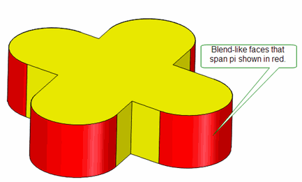
Figure 64-13 Controlling the identification of blend-like faces that span pi radians
You can identify blend faces with non-adjacent underlying faces using the
distant_unders
option. This option takes the following values:
|
Do not identify blend faces with non-adjacent underlying faces (Default). |
|
Note: Blend faces with non-adjacent underlying faces will only be correctly identified if there is also at least one adjacent underlying face. |
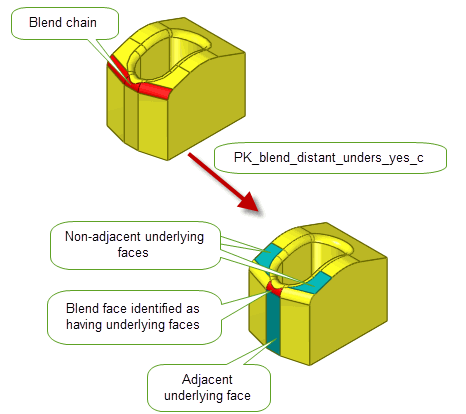
Figure 64-14 Identifying blend faces with non-adjacent underlying faces
You can use the
report_blends
option to control whether to generate a Parasolid Report for blend faces that have been identified, even if it they do not have underlying faces. It takes the following values:
|
A Parasolid Report of type PK_REPORT_record_type_3_c is generated indicating which blend faces have been identified and their underlying faces if present. |
|
This report contains additional information for blend faces to that returned in the PK_FACE_identify_blends_r_t return structure. See Section 64.5.9, “Returned information”, for more information.
See Chapter 11, “Using Reports”, for more information about the Parasolid Report mechanism.
You can control the information that PK_FACE_identify_blends returns using the
want_radii
and
want_convexities
fields in PK_FACE_identify_blends_o_t.
want_radii
is PK_LOGICAL_true, then the radius of each blend returned by PK_FACE_identify_blends is returned.
want_convexities
is PK_LOGICAL_true, then the convexity of each blend returned by PK_FACE_identify_blends is returned
In each case, the information is returned in the PK_FACE_identify_blends_r_t return structure as an array parallel to the
blend_facesets
array.
You can control whether blend chains are post-processed using the
optimise_chains
option. This has the following values:
|
Blend chains identified and processed to support reblending operations. |
You can use PK_FACE_find_blend_unders to identify the faces underlying a given constant radius blend face. This function receives a blend face (as identified by PK_FACE_identify_blends) and, optionally, a tolerance, and returns the array of faces that underlie the blend.
Figure 64-15 shows several blends (shown in red), together with the underlying faces that are returned by PK_FACE_find_blend_unders (shown in blue).
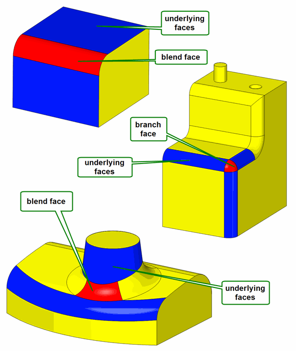
Figure 64-15 Finding the faces that underlie a blend
PK_FACE_find_blend_unders takes the following options:
tolerance |
The tolerance used to identify the received |
update |
Update switch to maintain consistency when rebuilding models built in older versions of Parasolid. See Section 62.5.2, “Update control”, for information. Default: PK_local_ops_update_default_c. |
PK_FACE_identify_blends and PK_BODY_identify_details contain powerful options to let you control whether or not a given detail is returned based on its radius. These controls are available in the following options:
limit_radii |
||
hole_cyl_radius |
||
hole_blend_radius |
Each of these options is a PK_double_constraint_t structure that contains two elements:
interval
containing a low and a high value.
interval
.
When the function finds a detail (for example, a hole), the radius of that detail is tested using the supplied
interval
and
comparison
. If the result of this comparison is true, then the function returns the detail. If the result is false, then the detail is not returned.
The comparison operations available are as follows:
Note: If the
details
supplied to PK_BODY_identify_details includes PK_detail_hole_cyl_c, then you must change the default setting for
hole_cyl_radius
in order to identify any cylindrical holes. |
|
Note: This functionality does not support facet geometry. |
You can use PK_FACE_classify_details to classify facesets according to the type of detail they represent. This function receives and returns the following arguments:
n_facesets facesets |
An array of facesets that you want to classify in terms of detail types. |
details |
An array of detail types by which to classify the given facesets. There should be one detail for each faceset provided. You can choose to classify the following detail types: |
options |
An options structure. See Section 64.8.1. |
results |
A structure containing an array of detail definitions that contain the following information:
See Section 64.8.2. |
|
Note: This functionality does not support facet geometry. |
The PK_FACE_classify_details_o_t options structure contains a
hole
sub-structure that contains options to control how holes are classified. The
hole
sub-structure contains the following options:
up |
For through-holes, this option specifies a vector that determines at which end of the through-hole to place the hole’s |
include_zero_depth |
Whether to include zero-depth components (i.e. components that are orthogonal to the hole’s axis) in hole components. This setting has no effect on the |
want_profiles |
Whether to return a profile for each hole component in the |
simplify_geom |
Whether to return original geometry or simplified geometry in the |
cb cb_context |
PK_FACE_classify_details provides support for callback functions so that you can return arbitrary information for each detail classified. This support is provided via the
You can use this callback functionality for any purpose you wish. A typical use would be to implement a system to automatically classify holes into the different types defined by your application, based on the components they contain. |
face_tracking |
Whether to track the faces that comprise hole components, in addition to surfaces.
By default, Parasolid only returns information about the surface that forms a hole component. This surface is returned by PK_FACE_classify_details in the
If |
PK_FACE_classify_details returns a
detail_defs
structure that maps each
detail_type
found to the
faces
that comprise that detail, and a sub-structure that contains data about each detail.
The
hole
sub-structure is used to return data about each hole detail classified, and includes the following information:
origin total_depth smallest_radius |
The origin (i.e. the position and orientation) of the hole detail described as an AXIS2 standard form, together with the total depth of all components in the hole, and the smallest radius of any of its components. The smallest radius is intended to represent the smallest drill size required for the hole: it therefore ignores the face that closes a hole, and it ignores any bottom blend in a closed hole. See Figure 64-16. |
profile |
If |
cb_result |
The integer return value of any callback function specified in |
n_components components |
The number of components in the hole detail, together with a structure that describes each component in terms of its type, depth, and a data parameter and entity associated with the component. See the documentation for PK_hole_comp_t for details about the data parameter and entity associated with each type of hole component. Figure 64-16 shows an imaginary hole that illustrates all the hole component types that can be classified. |
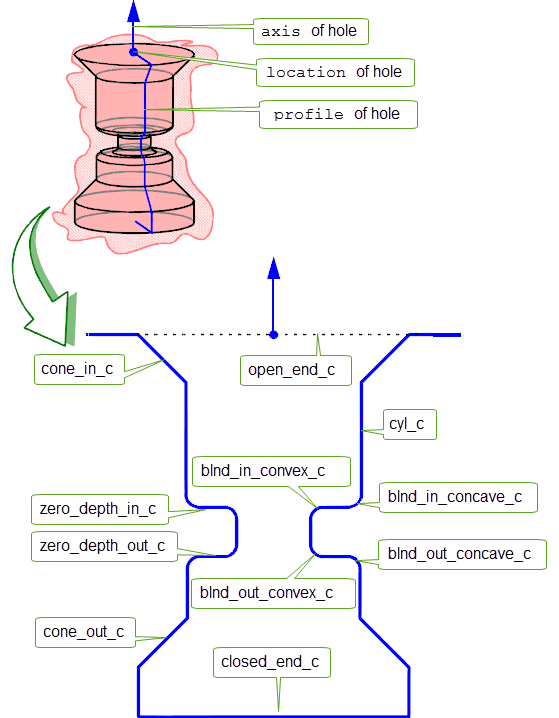
Figure 64-16 Classifications of hole components
| <<< Deleting Entities | Chapters | Replacing The Surfaces Of Faces >>> |