 |
Model Structure |
Model Structure
| <<< Parasolid Concepts | Chapters | Session and Local Precision >>> |
This chapter also discusses the relationships between topological and geometric entities (Section 3.6), including the way Parasolid represents edges and curves in models that use precisions other than the default Parasolid precision (Section 3.7). For more information about the use of precision in Parasolid, see Chapter 4, "Session and Local Precision".
You can find information about the connections between these entities using the many PK enquiry and output functions that are available. See Chapter 38, "Enquiry and Output Functions", for details.
|
Note: The general relationships between geometric, topological, and other entities are shown in Figure 2-1 in Section 2.2, "Entity classes, tokens and tags". You may find it useful to refer to this figure when reading the material in this chapter. |
Topological entities comprise all the entities that constitute the structure or skeleton of a model. All topological entities are within the superclass PK_CLASS_topol.
|
Note: You can find the immediate superclass of any class using PK_CLASS_ask_superclass. |
Bodies are fundamental to modeling with the PK. A body is composed of one or more components, where a component is a set of connected entities. The following types of component are available:
The following types of body are available:
| Type | Dim | Description |
|---|---|---|
|
One or more acorn components. An acorn body has one infinite void region, containing any number of shells, each of which contains only a single vertex. A minimum body is a special case of an acorn body containing exactly one isolated vertex. You can create a minimal body using PK_POINT_make_minimum_body . |
||
|
One or more wire components. A wire body has one infinite void region containing any number of shells, each of which contains a single set of connected edges. Figure 3-1 (a) illustrates valid and invalid wire bodies. |
||
|
One or more sheet components. A sheet body that contains only open components has one infinite void region containing any number of shells, each of which contains a single set of connected faces. For each closed component, there is an extra bounded void region representing the interior of the closed component. Figure 3-1 (b) illustrates valid and invalid sheet bodies. |
||
|
One or more solid components. Each solid component has a continuous bound volume. A solid body has one infinite void region, one solid region for each continuous solid volume, and one void region for each bounded continuous void volume. |
||
A body that contains more than one component is called a disjoint body.
For example, a disjoint sheet body would consist of several sheet components. Each sheet component would be composed of one or more connected faces which may be open or closed.
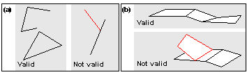
Figure 3-1 Valid and invalid wire (a) and sheet (b) bodies
Bodies can contain the following topological entities:
In addition, every face, edge and vertex in a body requires an attached geometric entity - a surface, curve or point - for a fully defined, valid model.
A region is an open connected subset of 3-dimensional space whose boundary is a collection of vertices, edges, and oriented faces. Regions are either solid or void (empty), and they may be non-manifold.
A body always has an infinite void region (which you can think of as all the space outside of the body itself), and the sum of all regions in a body comprises the whole of 3D space.
For example, the hollow cube shown in Figure 3-2 can be thought of as a collection of three regions:

Figure 3-2 Hollow cube consisting of three regions
Two regions may share a face, so that one region is on each side of the face. Figure 3-3 illustrates a partitioned general body with three regions, two of which are solid and share a common face (the partition face).

Figure 3-3 General body partitioned by an internal face
The shells in a region do not overlap or share faces, edges or vertices. A region may have no shells, in which case it represents all space (and is the only region in its body, which has no faces, edges or vertices).
A shell is a connected collection of oriented faces (each used by the shell on one or both sides of the face) and edges. A shell has:
Each pair consists of a face and a logical that indicates either the front (true) or the back (false) of the face. The front of the face is the side towards which the face normal points. The region to which the shell belongs lies on the indicated side of the face.
The edges represent 1-dimensional cuts in the shell's region (referred to as wireframe edges).
A shell may also consist of just a single vertex, referred to as an acorn vertex.
A face is a bounded subset of a surface, whose boundary is a collection of zero or more loops. It is a 2-dimensional analogy of a region.
A face with zero loops forms a closed entity such as a full spherical face.
A loop is a connected component of a face boundary. It is the 2-dimensional analogy of a shell. A loop can have:
The order of any fins represents the order that their owning edges are connected to each other via common vertices in the loop, taking the sense of each fin into account.
A loop may not contain the same edge more than once in each direction.
The direction of the loop is such that the face is locally on the left of the loop, when seen from above the face and looking in the direction of the loop. For more information about the direction of a loop, see Section 3.6.4, "Loop, fin and edge directions".
If the loop has any fins, the vertices must be connected to the edges which own the fins. If the loop has no fins, there must be only one vertex.
Consequently, a loop must be one of the following:
Parasolid distinguishes between several different types of loop. A loop's type depends on the underlying surface of the face to which the loop belongs.
Vertex loops and wire loops are generic return values that cover simple degenerate special cases; on solid and sheet bodies these loop types correspond to edges and vertices scribed inside a face, as shown in Figure 3-4.
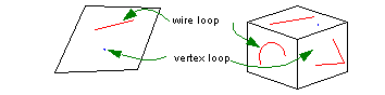
Figure 3-4 Vertex and wire loops
Each face on a non-periodic surface contains one outer loop (around the periphery of the face) and any number of inner loops (holes in the face). This is illustrated in Figure 3-5.
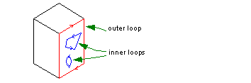
Figure 3-5 Outer and inner loops on a face
Closed loops that wind once around the periodic parameter space of cylindrical topology (i.e. bodies that are periodic in one parameter only) are known as winding loops.
To define the periphery of a face in a surface like this, you need either:
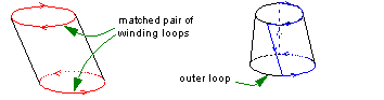
Figure 3-6 Defining cylindrical face peripheries using winding and outer loops
Like non-periodic faces, cylindrical topology can contain any number of inner loops.
Surfaces such as cones, that are periodic in one parameter and degenerate at one end, contain just one outer loop, and any number of inner loops. Inner loops are also winding if they surround the degeneracy, as shown in Figure 3-7. Such loops are known as inner singularity loops.
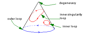
Figure 3-7 Loops in conic topology
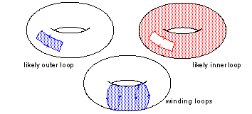
Surfaces that are periodic in both parameters, such as doughnut tori, can have winding loops that wind one or more times in either parameter. Any other loops form either the periphery of open regions (outer loops), or holes in the whole closed surface (inner loops).
Closed loops in spherical topology (closed in one parameter and degenerate in the other) split the whole surface in two. There are three types of closed loop on a spherical surface:
These types of loop apply to spherical topology in which the degeneracy is either smooth or sharp in 3D.
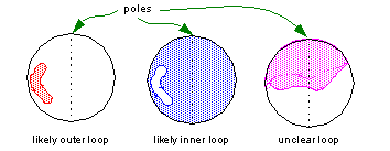
Figure 3-9 Loops on spherical topology
You can find the type of a given loop using PK_LOOP_ask_type.
A fin represents the oriented use of an edge by a loop. A fin has:
An edge is a bounded piece of a single curve. Its boundary is a collection of zero, one or two vertices. It is a 1-dimensional analogy of a region.
The ordering of the fins represents the spatial ordering of their owning faces about the edge, when applying the right-hand cork screw rule, i.e. looking in the direction of the edge the fin ordering is clockwise. For more information about the direction of a loop, see Section 3.6.4, "Loop, fin and edge directions".
An edge may have zero or any number of fins:
You can use PK_EDGE_ask_type to return information about any given edge.
If one of the vertices is null, then the other must be as well. When this is the case, the edge represents a whole periodic curve.
A vertex represents a point in space. It is the zero-dimensional analogy of a region. A vertex has a single point, which may be null
An assembly is a collection of instances, where each instance references
An assembly cannot directly or indirectly instance itself. Thus, the tree of assemblies and parts must not be cyclic, as illustrated in Figure 3-10.
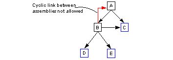
Figure 3-10 Cyclic and acyclic trees of assemblies and parts
An assembly can also have construction geometry, consisting of surfaces, curves and points that are attached directly to the assembly.
Use PK_ASSEMBLY_create_empty to create a new, empty assembly.
Use PK_ASSEMBLY_ask_part_transfs to return all the parts and transforms in a given assembly.
The transform must be a rigid motion. No scaling or rotation motion can be used.
An instance references its owning assembly, the part it instances, and a transform. If the transform is null, it is treated as the identity transform.
Use PK_INSTANCE_create to create a new instance. This function assumes that the part and transform referenced by the instance have already been created.
There are three classes of geometric entity: PK_CLASS_surf, PK_CLASS_curve, and PK_CLASS_point. All three have the immediate superclass PK_CLASS_geom.
The principle function of geometric entities is to specify the geometric relationships in body (referred to as principle geometry). In a completely defined part, these relationships are specified using geometric entities that are attached to topological entities, according to the relationships shown in Figure 3-11.
Geometric entities may also be attached directly to a body to form construction geometry, as a means of keeping relevant entities with the body. For example, you might want to attach a point to a body that represents its center of gravity. This is shown in Figure 3-11.
Geometric entities can also be manipulated independently of any body. Orphan geometry is geometry not attached to any topological entity, even a body. It is attached to the current partition instead. This is useful if you want to create geometry prior to using it in a body, for example, to create a surface before incorporating it into a body.
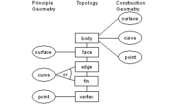
Figure 3-11 Geometric and topological entities
Surfaces are principally attached to faces, but may also be attached to bodies as construction geometry. Normally every face has an attached surface, but it may be detached temporarily as the model is being built or modified. The following types of surface are available in Parasolid:
All of the classes listed above have the immediate superclass PK_CLASS_surf.
Curves are principally attached to edges or fins of the model, and may also be attached to bodies as construction geometry. Curves occur in the following classes:
All of the classes above have the immediate superclass PK_CLASS_curve.
Points (PK_CLASS_point) are principally attached to vertices, and may also be attached to bodies as construction points. All points are Cartesian Points.
In order to reduce the overall size of a model, geometric entities can be shared where appropriate. Geometry sharing only occurs in a single body and works for the following cases:
The following types of session object are used for rollback management.
A partition is a collection of parts and other data whose state can be rolled back and forward within a session independently of other partitions, to assist your application with feature modeling. All topological and geometric entities in a given session are contained in some partition. A session may have only one partition, in which case all entities are in that partition.
The following objects relate to partitions, and are for use with rollback.
Pmarks are rollback marks set in a partition to record the state of the partition at that point. A partition can be rolled forward or backward to any pmark that has been set. Setting a pmark creates a delta.
Deltas record the changes required to move from one pmark to an adjacent one. They are output through the delta frustrum.
Marks record the state of the entire modeling session at a given point. A mark is set by creating a pmark in each partition.
|
Note: Partitions can also be saved and retrieved as a complete item. The file contains the partition's pmarks (and optionally its deltas) as well as the bodies being modeled in that partition. |
There are other Parasolid entities available that manipulate and attach additional data to a model, or define extra structure.
These are data structures that can be attached to any single topological or geometric entity, or any group. They contain fields of particular types that are specified in an attribute definition.
The data stored in attributes, and the existence of the attributes, is either automatically updated when their owning entities are involved in modeling operations, or can be controlled by the user via callbacks.
These are collections of entities within a body. They can refer to faces, edges, vertices, surfaces, curves and points, or a mixture of all of these classes. Groups are useful in feature modeling: for example, you can create a feature such as a boss and create a group that contains all the entities that constitute it. You can then identify the feature by attaching a single attribute to the group, rather than having to attach attributes to each of the individual entities.
Groups containing entities modified in modeling operations are automatically updated by the kernel.
These express geometric operations: translations, reflections etc. They may be used directly in the specification of certain modeling and rendering operations (such as creating assemblies). They are sometimes known as transformations.
This section discusses in more detail the relationships between topological entities and the geometric entities that can be attached to them.
The normals of the faces in a solid body ( face normals) must point away from the solid region.
For faces of an outer shell, the normals point outwards. For an inner shell (i.e. a void inside a solid) the face normals point inwards, that is, still away from the solid.
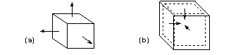
Figure 3-12 Face normals of (a) a body, and (b) an inner shell
It is possible to have a solid that is inside out, so that the face normals point into the solid. Such a body is called a negative body. The only operation that can be performed on a negative body is to negate it.
Face normals must also point away from the body for sheet bodies. The face normals in a sheet body must be consistent, as shown below.
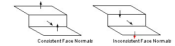
Figure 3-13 Face normals of sheet bodies
The orientation of a surface depends on its geometry. Every surface has a natural orientation. For example:
| Surface | Natural orientation |
|---|---|
In parametric form, the orientation is along dU X dV.
The relationship between a face and its underlying surface is determined by the face orientation flag, which indicates the direction of the face normal with respect to the surface normal. If this flag is PK_LOGICAL_true, then the face normal is parallel to the surface normal, otherwise it is anti-parallel, as shown in Figure 3-14.
PK_FACE_ask_oriented_surf returns the surface underlying a face plus the face orientation flag. When the application requires a face normal at a given point, then it needs to call both this function and PK_SURF_eval_with_normal.
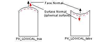
Figure 3-14 Face orientation flag
Loops, fins and edges have directions, and there are conventions that define the way they relate to the face normals and to each other. These conventions are as follows:
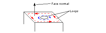
Figure 3-15 Loop directions of the top face of a cube with a cylindrical pocket
The direction of a face's loop determines the direction of the edges and fins of that face:
|
Note: The left fin is the one that is returned first when the fins of an edge are enquired. |
The curve direction is determined by the curve tangent, which is always in the direction of increasing parameter value.
The relationship between the direction of an edge or fin and the direction of its underlying curve is determined by the edge/fin orientation flag. If this flag is PK_LOGICAL_true, then the direction of the edge or fin is parallel to the underlying curve tangent, otherwise it is anti-parallel.
PK_EDGE_ask_oriented_curve and PK_FIN_ask_oriented_curve both return the following values:
When your application requires an edge or fin direction at a given point, then it needs to call one of these functions, together with one of the following:
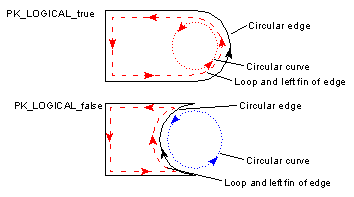
Figure 3-16 The relationship between the direction of the curve and its owning edge/fin
An exact edge is an edge that has been created in Parasolid and is represented by an untrimmed 3-space curve, which is attached to the edge itself.
An edge with local precision (for example, an edge which has been created by another modeler and is therefore not necessarily modeled to Parasolid tolerance) is represented by an SP-curve attached to each fin. The only geometry that may be attached to an edge with local precision is nominal geometry (see Section 3.7.3).
When an accurate edge is made tolerant, the 3-space curve on the edge is normally detached and deleted (unless used by another edge). Nominal Geometry is a mechanism whereby this 3-space curve can be retained on the edge or associated with the edge manually.
| <<< Parasolid Concepts | Chapters | Session and Local Precision >>> |