Types of Local Operations
Topics include:
Tweak
- Scheme Extensions:
- lop:tweak-faces, lop:tweak-faces-extend, lop:tweak-faces-init, lop:convert-pipes
-
C++ APIs: - api_convert_pipes, api_tweak_faces, api_tweak_fix_edge, api_tweak_fix_vertex, api_tweak_extend_faces, api_tweak_query_edge_solutions, api_tweak_pick_edge_solution
The tweak algorithm is the foundation for all other local operations. It can change the surfaces of any number of faces to any other surfaces supplied by the user, providing that the surfaces intersect appropriately and that necessary topology changes are supported. Specific faces can be selected, or an array of faces. In this example, the top surface of the block is tweaked to the tool face.
Scheme Example
| ; lop:tweak-faces ; Create a solid block. (define block1 (solid:block (position -20 -20 -20) (position 20 20 20))) ;; block1 ; Create a tool face (define face1 (face:plane (position -10 -10 0) 20 20 (gvector 0 0 1))) ;; face1 ; OUTPUT Original ; Tweak face of the body (lop:tweak-faces (pick:face (ray (position 10 0 0) (gvector 0 0 1))) face1 #f) ;; #[entity 2 1] ; OUTPUT Result |
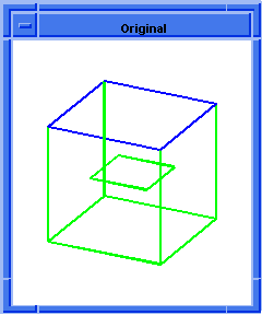
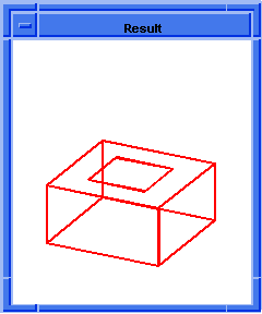
Figure. lop:tweak-faces
Move
- Scheme Extensions:
- lop:move-faces, lop:rotate-faces, lop:sweep-more
-
C++ APIs: - api_move_faces, api_sweep_more
The move API moves an array of faces through a transform, which replaces the surfaces of the specified faces with the surfaces which are moved by the transform. The translation vector of the transform must be non-zero or an error results.
In the first example, the top surface of the block is replaced by the surface moved by the gvector transform. In the second example, lop:sweep-more extends the end face of the swept spring.
Scheme Example
| ; Move Example 1 - lop:move-faces ; Create a solid block. (define block1 (solid:block (position -20 -20 -20) (position 20 20 20))) ;; block1 ; OUTPUT Original ; List the faces of the block (entity:faces block1) ;; (#[entity 3 1] #[entity 4 1] #[entity 5 1] ;; #[entity 6 1] #[entity 7 1] #[entity 8 1]) ; Move a face on the body (lop:move-faces (entity 4) (gvector 10 10 20)) ;; #[entity 2 1] ; OUTPUT Result |
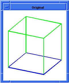
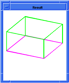
Figure. lop:move-faces
| ; Example 2 - lop:sweep-more ; Make a spring (define path (edge:law "vec(cos(x),sin(x),x/10)" 0 10)) ;; path ; Define a profile (define profile (edge:ellipse (position 1 0 0) (gvector 0 1 0) (gvector .2 0 0))) ;; profile (define sweep (sweep:law profile path)) ;; sweep ; sweep => #[entity 4 1] ; Zoom to see the model (zoom-all) ;; #[view 1076896136] (render:rebuild) ;; () ; OUTPUT Original and OUTPUT Rendered Original ; Pick the face to sweep more (define f (pick:face (ray (position 1 0 0) (gvector 0 -1 0)))) ;; f (lop:sweep-more f 1) ;; #[entity 4 1] (render) ;; () ; OUTPUT Result and OUTPUT Rendered Result |
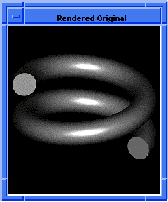
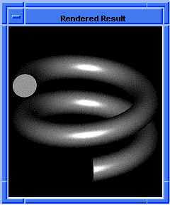
Figure. lop:sweep-more
Offset
- Scheme Extensions:
- lop:offset-body, lop:offset-faces, lop:offset-specific
-
C++ APIs: - api_offset_body, api_offset_faces, api_offset_faces_specific, api_offset_planar_face_loops
The offset APIs offset a body or an array of faces by an offset distance. In face offsetting and body offsetting, radial faces whose geometry would degenerate as a result of the offset are removed prior to the offset. Thus, if a body with blended edges or vertices is offset inwards by more than the blend radius, the blends are removed prior to the offset. This uses the "remove faces" functionality (for example, shells may be split). If some faces can not be removed, the offset fails.
In the first example, the top surface is offset vertically. In the second example, all the surfaces are offset, resulting in a larger block.
Scheme Example
| ; Offset Example 1 - lop:offset-faces ; Create a solid block. (define block1 (solid:block (position -10 -10 -20) (position 5 30 20))) ;; block1 ; OUTPUT Original ; Offset a face on the body (lop:offset-faces (pick:face (ray (position 0 0 0) (gvector 0 0 1))) 10) ;; #[entity 2 1] ; OUTPUT Result |
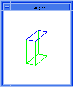
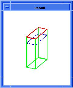
Figure. lop:offset-faces
| ; Offset Example 2 - lop:offset-body ; Create a solid block. (define block1 (solid:block (position -10 -10 -20) (position 20 15 20))) ;; block1 ; OUTPUT Original ; Offset the body (lop:offset-body block1 15) ;; #[entity 2 1] ; OUTPUT Result |
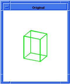
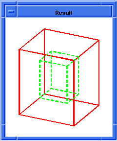
Figure. lop:offset-body
Taper
- Scheme Extensions:
- lop:taper-faces, lop:edge-taper-faces
-
C++ APIs: - api_taper_faces, api_shadow_taper_faces, api_edge_taper_faces
A plane taper is often used to facilitate extraction of a part from a mold rather than to change the general appearance of a model. Typically the angle supplied would be very small. It replaces the surfaces of the supplied faces with surfaces tapered by a draft angle about the intersection between the draft plane and the surface. Whether the taper is executed or just validated is controlled by the option validate_lop.
From R11 onwards, the definition of the taper surface has been changed. In the case of plane tapers, the new face surfaces are defined as the envelope surfaces of cones whose apices ride along the intersection curve of the respective faces and the taper plane, whose axes are specified by the taper plane normal, and whose half-angles are equal to the supplied draft angle. In the case of edge tapers, the new face surfaces are defined as the envelope surfaces of cones whose apices ride along the respective face edge curves, whose axes are given by the supplied draft angle, and whose half-angles are equal to the supplied draft angle.
Thus, with the old taper definition each successive plane taper operation on the same face with the same draft angle and taper plane would result in an additional rotation of the rulings by the supplied draft angle thereby resulting in a new surface. With the new taper definition however, after the first plane taper, subsequent plane taper operations on the same face with the same draft angle and taper plane will effectively produce the same taper surface, as the envelope cone stays the same and it rides along the same intersection curve as in the first plane taper operation. The same situation exists in the case of edge tapers.
With the old taper definition tangent edges shared between two taper faces may not remain tangent after the taper operation. With the new taper definition, however, such edges are guaranteed to remain tangent, regardless of whether the taper operation is an edge or plane taper.
To know the difference in functionality between R11 release and pre-R11 release, click here.
The taper operation can include vent faces. If one face of a mergeable edge is to be tapered and the edge does not lie in the draft plane, the taper algorithm adds a vent face. The vent face lies between the edge on the face that is not tapered and the corresponding edge on the tapered face. If the mergeable edge intersects the draft plane, the edge is split at the intersection point and two vent faces are inserted. The simplest surface definition possible is used for the vent face. All curves on planar or conical faces are supported.
In a shadow taper, the shadow is caused by a beam of light traveling with the draft direction and angle. The shadow taper functionality fills in gaps that are not visible from a specified direction. It detects special geometry cases on spheres, cones, and tori, and makes a cone or plane for the taper surface rather than a spline.
Scheme Example
| ; Taper Example lop:taper-faces (define block2 (solid:block (position -25 -25 -10) (position 25 25 10))) ;; block2 (solid:blend-edges (pick:edge (ray (position 0 0 0) (gvector 1 -1 0))) 20) ;; (#[entity 4 1]) ; OUTPUT Original (lop:taper-faces (list (pick:face (ray (position 0 0 0) (gvector 1 0 0))) (pick:face (ray (position 0 0 0) (gvector 0 -1 0))) (pick:face (ray (position 0 0 0) (gvector 1 -1 0)))) (position 0 0 -10) (gvector 0 0 1) 45) ;; #[entity 4 1] ; OUTPUT Result |
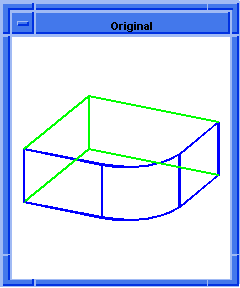
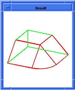
Figure. lop:taper-faces
| ; Taper Example lop:shadow-taper-faces ; Create a solid block (define block1 (solid:block (position -25 -25 -10) (position 25 25 10))) ;; block1 ; Create a solid cone (define cone1 (solid:cone (position -20 0 10) (position 20 0 10) 20 10)) ;; cone1 ; Unite the cone and block (bool:unite block1 cone1) ;; #[entity 2 1] ; OUTPUT Original ; Shadow taper a face on the body (lop:shadow-taper-faces (pick:face (ray (position 0 0 0) (gvector 0 0 1))) (gvector 0 0 1) 20) ;; #[entity 2 1] ; OUTPUT Result |
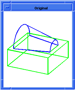
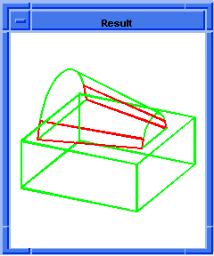
Figure. lop:shadow-taper-faces
| ; Example edge taper merging vent faces. ; Define some entities (part:clear) ;; #t (define block1 (solid:block (position -25 -25 -25) (position 25 25 25))) ;; block1 (define block2 (solid:block (position -50 -50 0) (position 50 50 100))) ;; block2 (solid:imprint block1 block2) ;; #t (entity:delete block2) ;; () (option:set "annotation" #t) ;; #f (option:set "unhook_annotations" #f) ;; #t (define e1 (pick:edge (ray (position 0 0 -25) (gvector 1 0 0)))) ;; e1 (define f1 (pick:face (ray (position 0 0 -20) (gvector 1 0 0)))) ;; f1 (define e2 (pick:edge (ray (position 0 0 -25) (gvector -1 0 0)))) ;; e2 (define f2 (pick:face (ray (position 0 0 -20) (gvector -1 0 0)))) ;; f2 (define e3 (pick:edge (ray (position 0 0 -25) (gvector 0 1 0)))) ;; e3 (define f3 (pick:face (ray (position 0 0 -20) (gvector 0 1 0)))) ;; f3 (define e4 (pick:edge (ray (position 0 0 -25) (gvector 0 -1 0)))) ;; e4 (define f4 (pick:face (ray (position 0 0 -20) (gvector 0 -1 0)))) ;; f4 ; OUTPUT Original (lop:edge-taper-faces (list f1 f2 f3 f4) (list e1 e2 e3 e4) (gvector 0 0 1) 20) ;; #[entity 24 1] ; OUTPUT Result ; Render to see the final result. (render) ;; () ; OUTPUT Rendered |
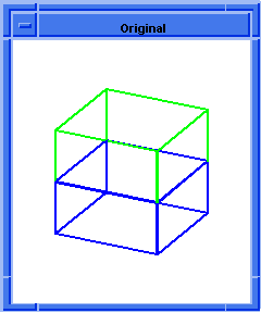
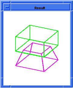
Figure. lop:edge-taper-faces
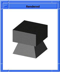
Figure. lop:edge-taper-faces, Rendered
From R11 onwards, the plane taper and the edge taper API's – api_plane_taper_faces and api_edge_taper_faces use a new definition of taper to produce the new taper surfaces for the faces to be tapered. Please note that the arguments to both API's are the same as in R10.
In the case of plane tapers the new taper surfaces are defined as the envelope surfaces of cones whose apices ride along the intersection curve of the respective faces and the taper plane, whose axes are specified by the taper plane normal, and whose half-angles are equal to the supplied draft angle. In R10 and before the new surfaces were defined by rotating the rulings along the draft direction on the supplied faces by the given draft angle about the intersection curve of the draft plane and the surfaces of the supplied faces.
In the case of edge tapers the new surfaces are defined as the envelope surfaces of cones whose apices ride along the respective face edge curves, whose axes are given by the supplied draft direction, and whose half-angles are equal to the supplied draft angle. In R10 and before the new surfaces are defined by rotating the surface rulings along the draft direction on the supplied faces by the given draft angle about the corresponding edges.
Thus in the case of both plane and edge tapers the interpretation of the supplied draft angle has changed.
Interpretation of Draft Angle Is Different
The following scheme example shows how the new taper surface differs from the old taper surface in a simple case.
| (part:clear) (option:set "sil" #t) (front) (wcs (position 0 0 0)(gvector 1 0 0)(gvector 0 1 0)) ;; Make an expanding cone(along +z) such that the ;; cone half angle is 11.31 degrees -- the angle by ;; which we will draft below (define b1(solid:cone (position 0 0 0)(position 0 0 50) 30 40)) (entity:set-color b1 RED) ;; Taper the conical face. From R11 onwards, the draft ;; angle is interpreted as the angle which the new ;; surface generators make with respect to the taper ;; plane normal. Note the taper plane is coincident ;; with the bottom face of the cone and we taper the ;; conical face. (define f (pick:face (ray (position 0 0 10)(gvector 1 0 0))1)) (lop:taper-faces f (position 0 0 0) (gvector 0 0 1) 11.31) ;; Roll to do the taper again. (roll) (wcs (position 100 0 0)(gvector 1 0 0)(gvector 0 1 0)) ;; Now taper the conical face using the old taper ;; algorithm. The draft angle is this case is ;; interpreted as the angle by which the cone ;; generators are rotated about the taper plane. This ;; results in the cone becoming a cylinder as the ;; original cone half angle is nearly 11.31. (define f (pick:face (ray (position 0 0 10)(gvector 1 0 0))1)) (lop:taper-faces f (position 0 0 0) (gvector 0 0 1) 11.31 (acisoptions:set 'version (versiontag 10 0 0))) |
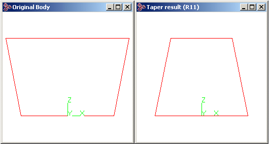
Figure. Interpretation of Draft Angle - R11
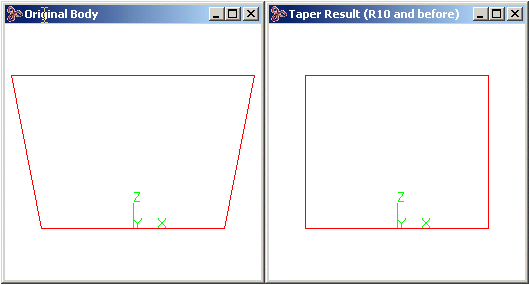
Figure. Interpretation of Draft Angle - R10
The second important difference between the old and the new taper definition is with regards to tangency of edges. With the new taper definition tangent edges both of whose faces are tapered always stay tangent after an edge taper operation when their corresponding faces edge curves are also tangent. This was not always true with the old definition of taper. The same situation exists in the case of plane tapers too.
Tangent Edges Stay Tangent
| ;; Make a block (view:dl) (view:set-bg-color 7) (define b(solid:block 0 0 0 50 50 50)) (entity:set-color b RED) ;; Blend an edge (solid:blend-edges (pick:edge (ray (position 5 0 5)(gvector -1 0 0)))15) ;; Make a sphere (define s(solid:sphere (position 25 25 70) 50)) ;; Subtract the sphere from the block (solid:subtract b s) (wcs (position 0 0 0)(gvector 1 0 0)(gvector 0 1 0)) ;; Define the edges to be tapered as the edges adjacent to the spherical face and the ;; blend face and its supports (define eds (list (pick:edge (ray (position 4.4 4.4 1)(gvector 0 0 1))))) (pick:edge (ray (position 0 32 1)(gvector 0 0 1))) (pick:edge (ray (position 32 0 1)(gvector 0 0 1))) ;; Define the faces to be tapered as the blend faces and ;; its supports (define fas (list (pick:face (ray (position 0 0 1)(gvector 1 1 0))1))) (pick:face (ray (position -1 32 1)(gvector 1 0 0))1) (pick:face (ray (position 32 -1 1)(gvector 0 1 0))1))) ;; Pick a blend support edge, and check its convexity (define smooth_edge (pick:edge (ray (position 0 32 5)(gvector 0 -1 0)))) (entity:set-color smooth_edge BLUE) (edge:convexity smooth_edge) ;;"convex_smooth" ;; Now taper the blend face and its supports (lop:edge-taper-faces fas eds (gvector 0 0 -1) 5) ;; Check the convexity of the support edge again. (edge:convexity smooth_edge) ;;"convex_smooth" ;; If the old taper is done then the support edge will not remain tangent anymore. ;;(lop:edge-taper-faces fas eds (gvector 0 0 -1) 5(acisoptions:set 'version (versiontag 10 0 0))) ;;(edge:convexity smooth_edge) ;;"convex" |
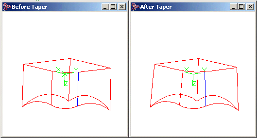
Figure. Tangent Edges
Sheetbody Extend
- Scheme Extensions:
- lop:extend-sheet
-
C++ APIs: - api_extend_sheetbody
Extends a sheet body (that is, an open body) by the limiting edges (those edges whose coedges do not have a partner). The geometry of the specified edges is offset inwards or outwards depending on the offset distance sense. The surfaces contained in the faces are extended accordingly to fill the gap created by the offset distance in a natural way.
Offset Edges
The offset edges are measured by the perpendicular distance between the original curve and the resulting curve. In planar cases this is easy to visualize, for example, the offset of a circle is a another circle, a straight line is another straight line. A spline or procedural curve is processed and is returned with the same properties of a planar wire offset.
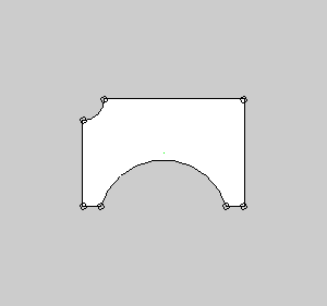
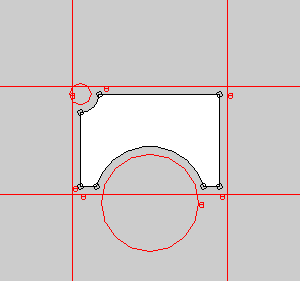
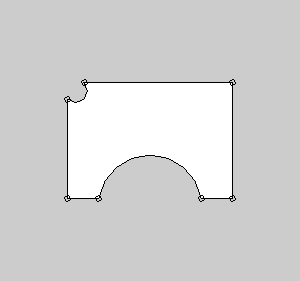
Figure. Planar Sheetbody Extend
All the limiting edges are to be offset, showing its solution curves; result to the right.
Non planar cases, however, are created in a different way. The resulting curve is offset in a manner that the 3D distance between the two is the specified offset distance; the distance is not measured along the surface (arc-length wise).
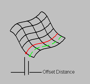
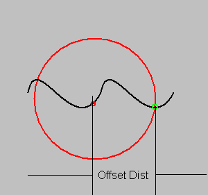
Figure. Offset Edge Not at Arclength Distance from Original
Surface Extensions
The surface is extended naturally; that is, it extends according to its compositions. A cone extends peridically in v and linearly in u; a plane is linear in both directions, a procedural surface extends depending on its defining components, and a pure bspline extends linearly beyond its original definition.
This concept is important for understanding where the resulting offset curves are to be defined.
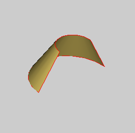
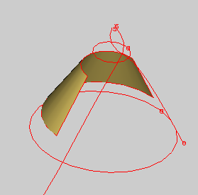
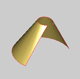
Figure. Non Planar Sheet Body Extend
Notice that the offset curves follow the xyz offset distance, not the arc length distance. In this example, the straight line became a spline curve. Also, notice that the surface extended in a natural way.
Vent Edges
A vent edge is a new, made-from-inside-LOPs edge that fills the gap between one moving and one fixed edge. Generally these edges grow perpendicularly from tangential two-edge vertices. In three-edge vertices, the intersection between the two surfaces grows and fills the gap.
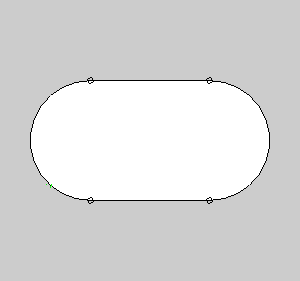
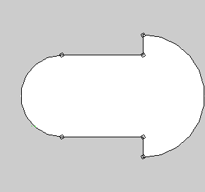
Figure. Vent Edges
Scheme Example
|
; lop:extend-sheet |
Related topics:
Topology
Adaptive Offset
Body Repair
Blended Faces
Remove Faces
Defeaturing
Limitations
[Top]
© 1989-2007 Spatial Corp., a Dassault Systèmes company. All rights reserved.