Remove Faces
The Remove Faces Component (REM), supports removal of faces and other topological elements after a local operation and heals the resulting body with the remaining faces.
REM simplifies a body by removing redundant faces and mending the gap that is left, when this is geometrically possible. If it is not possible, the model is left unchanged and an error is raised. The body's shells and lumps are corrected at the end of the operation, if they have been split. The API function api_remove_faces is used to perform this operation.
REM has the following limitations:
- The body must be manifold and solid.
- Some remaining faces may shrink if necessary, but not so far as to let edges between them degenerate to zero length. The mending process must be entirely within the faces adjacent to those removed.
- No checks are made to see if the faces grown intersect with other non-growing faces in the model. Checks that the growing faces intersect with one another is not rigorously done between unconnected regions of growing faces.
- Mixed convexity blended vertex faces are generally not removable in isolation, as the underlying blends cannot combine to mend the gap. Such vertices can, however, be removed along with one or more of their underlying blends.
The following scheme examples illustrate the some of the functionality of REM.
Removing a Vertex Blend
Scheme Example
| (part:clear) (define block1 (solid:block (position -25 -25 -25)(position 25 25 25))) (iso) (zoom-all) ; Attach blend attribute to edge 0. (define attach0 (blend:round (list-ref(entity:edges block1) 0) 10)) ; Attach blend attribute to edge 3. (define edge3 (blend:round (list-ref(entity:edges block1) 3) 10)) ; Attach blend attribute to edge 9. (define edge9 (blend:round (list-ref(entity:edges block1) 9) 10)) ; OUTPUT Original ; Attach blend attribute for autoblend on vertex 0 (define autoblend0 (blend:vertex (list-ref(entity:vertices block1) 0) "autosetback")) ; Execute blend on vertex and edges. (blend:fix (list-ref (entity:vertices block1) 0)) (view:refresh) ; pick the vertex blend (ray:queue 266.786 -369.845 205.129 -0.529697 0.747274 -0.401252 1.97972) (define rem_face (pick-face)) (entity:set-color rem_face RED) ; remove the face (rem:remove-faces rem_face) |
Figure. Removing a Vertex Blend
Shells or Lumps Separating
Shells and lumps may be split into two or more lumps when faces are removed. Shells of opposite solidity to the original are deleted. Faces left infinite are also removed, such as planar faces with no edges.
Scheme Example
| (part:clear) (define b1 (solid:pyramid 50 25 25 5)) (iso) (zoom-all) (entity:move b1 0 0 -26) (define b2 (entity:copy b1)) (entity:rotate b2 0 1 0 180) (solid:unite b1 b2) (define b3 (solid:cylinder 0 0 -50 0 0 50 15)) (solid:unite b1 b3) (iso) (zoom-all) (ray:queue 63.6563 -126.896 59.6118 -0.408248 0.816497 -0.408248 1.97972) (define rem_face (pick-face)) (entity:set-color rem_face RED) (rem:remove-faces rem_face) |
Figure. Shells Separating
Using the Bounding Box
The user supplied bounding box must be large enough to contain the final grown remaining faces. As the box is used to limit surface-surface and curve-surface intersections, and curve or surface extensions, the smaller the box, the better the performance. The box default is twice the size of the original body box. This may be too small on bodies with acute angles between remaining faces.
Scheme Example
| (part:clear) (define b1 (solid:pyramid 50 25 25 10 10)) (ray:queue 58.9619 -117.507 83.0834 -0.408248 0.816497 -0.408248 1.97972) (define rem_face (pick-face)) (entity:set-color rem_face RED) (rem:remove-faces rem_face (position -50 -50 -50) (position 50 50 100)) |
Figure. Using the Bounding Box
Remove Wire Edges
The Remove Wire Edges component (SPArem) supports the removal of wire edges from a wire body. The gap left behind upon the removal of the edges is filled by extending the neighboring edges. If the gap cannot be filled by the extension of the neighboring edges, that is, if there is no intersection possible between the extending edges (within the limits of the bounding box specified), then the input wire body is left unchanged and an error is returned. The API function api_remove_wire_edges or the scheme extension rem:remove-wire-edges is used to perform this operation. This API works on both open and closed wire bodies.
Remove Wire Edges has the following limitations:
- The wire body must be manifold.
- If the edges adjacent to the edges being removed do not have well-defined extension behavior, this can cause the API to fail.
Scheme Examples
The following scheme examples illustrate the functionality of Remove Wire Edges. The neighboring edges are extended naturally to fill the gap caused to the removal of wire edges. When an intersection point is obtained within the limits of the bounding box, the topology of the input wire body is modified.
| (part:clear) (define body (car (part:load "remove_wire_edge_02.sat" ))) (define edges (entity:copy (entity:edges body))) (entity:delete body) (define wire_body (wire-body edges)) (define edge (list-ref (entity:edges wire_body) 4))) (entity:set-color edge 1) (rem:remove-wire-edges edge) (part:clear) |
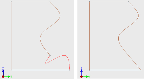
Figure. Remove Wire Edges: Extended Edges
If the intersection involves two identical curves such as straights, then a vertex is placed between the two edges based on an average distance.
| (part:clear) (define wire1 (wire-body (list (edge:linear (position 0 -10 0) (position 50 -10 0)) (edge:circular (position 75 -10 0) 25 180 360) (edge:linear (position 100 -10 0) (position 150 -10 0))))) (define edges (list (list-ref (entity:edges wire1) 1))) (entity:set-color edges RED) (rem:remove-wire-edges edges) (entity:check wire1) (part:clear) |
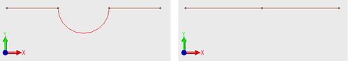
Figure. Remove Wire Edges: Straight Curves
If no intersection is possible between the neighboring edges in the direction of extension (even though there might be intersection possible in the opposite direction), then the API fails.
| (part:clear) (define e1 (edge:circular (position 0 0 0) 5 90 360)) (define e2 (edge:linear (position 0 5 0) (position 0 10 0))) (define e3 (edge:linear (position 0 10 0) (position 10 10 0))) (define e4 (edge:linear (position 10 10 0) (position 10 0 0))) (define e5 (edge:linear (position 10 0 0) (position 5 0 0))) (define wire (wire-body (list e1 e2 e3 e4 e5))) (define edgelist (list (list-ref (entity:edges wire) 2) (list-ref (entity:edges wire) 3))) (entity:set-color edgelist 1) ;*** Etrap rem:remove-wire-edges: gap cannot be filled (rem:remove-wire-edges edgelist) (part:clear) |
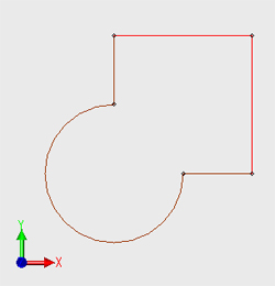
Figure. Remove Wire Edges: Invalid Result
In this case the intersection between the neighboring curves occurs in a direction opposite to that of extension; hence it is not considered valid.
Related topics:
Types of Local Operations
Topology
Adaptive Offset
Body Repair
Blended Faces
Defeaturing
Limitations
[Top]
© 1989-2007 Spatial Corp., a Dassault Systčmes company. All rights reserved.