
 |
Converting Between Facet and Classic Geometry |
| <<< Facet Model Structure | Chapters | Creating PSM Data From Foreign Facet Data >>> |
This chapter provides an overview on the different ways you can create facet bodies from classic bodies and classic bodies from mesh data. It also describes how you can create classic geometry from a mesh. These are discussed in the following sections:
For information on creating facet bodies from foreign mesh data see Chapter 85, “Creating PSM Data From Foreign Facet Data”.
You can create a mixed body from classic topology using the PK_TOPOL_make_facet_topol function. With this function, topological entities are specified from which to create new facet geometry by replacing curves and surfaces of the original classic body with facet data. PK_TOPOL_make_facet_topol allows you to add facet geometry to existing bodies without having to convert the entire body as illustrated in Figure 84-1.
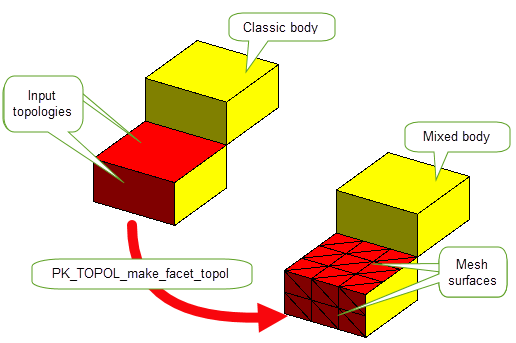
Figure 84-1 Creating a mixed body with PK_TOPOL_make_facet_topol
|
Provides controls for angular tolerance. See Section 84.2.1, “Controlling angular tolerance information” for more information. |
|
|
Controls the maximum length of a facet edge. See Section 84.2.2, “Controlling the sizes of facets” for more information. |
|
|
See Section 84.2.2, “Controlling the sizes of facets” for more information. |
|
|
Whether to store the normals of classic surfaces as mvertex normals in the meshes which replace them. Default: PK_LOGICAL_false. See Section 84.2.3, “Storing normals” for more information. |
|
|
Whether to return tracking records for all topological changes made to faces as part of the operation. Default: PK_LOGICAL_false |
|
|
Whether to return tracking records for all topological changes made to edges. See Section 84.2.4, “Tracking the edges on a facet body” for more information. Default: PK_track_edges_no_c. |
|
|
Whether to return tracking records containing all topological entities that were made redundant or merged out by the operation. |
|
|
Whether to return an array of all topological entities that were modified by the operation. This includes any edges and vertices that were created. |
You can control the angular tolerance using the
have_angular_tolerance
and the
angular_tolerance
options.
If
have_angular_tolerance
is PK_LOGICAL_true and
angular_tolerance
is a positive value, then it is used to control the sum of the angles in radians between a facet edge and the curve or surface tangents at each end.
You can control the sizes of the facets using the
max_facet_width
and
max_chord_length
options.
If
have_max_facet_width
is PK_LOGICAL_true and
max_facet_width
is a positive value, this value will control the maximum length of any facet edge in the meshes created for any supplied faces as shown in
Figure 84-2.
If
has_max_chord_length
is PK_LOGICAL_true and
max_chord_length
is a positive value, this value will control the maximum length of any polyline chord.
By default, Parasolid dynamically calculates the normals of meshes created to replace the input surfaces.
You can choose to store normals by setting the
store_normals
option to PK_LOGICAL_true. When set to PK_LOGICAL_true, the meshes created will have the same normals as the existing surfaces which they are replacing. See the API for more details on this option.
|
|
For more information about mesh normals, and managing mvertex normals, see Section 88.3, “Mesh normals”.
You can choose whether to return tracking information for edges using the
track_edges
option.This takes the following values:
You can create a facet body directly from an existing body using PK_BODY_make_facet_body. This function takes the body you wish to convert and a translation or rotation transform and returns a copy of the body with facet geometry attached in place of existing geometry.The original body is untouched. As well as controlling the linear and angular tolerance of the resulting attached mesh, you can also control the size of facets within the mesh, whether attributes and groups should be retained, and whether partial conversion to a facet body is allowed.
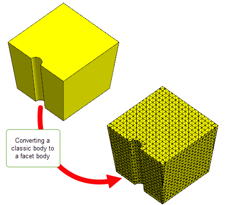
Figure 84-2 Creating a facet body from a classic body
This function takes the following options:
|
Whether See Section 84.3.1, “Controlling the sizes of facets” for more information. |
|
|
Controls the maximum length of a facet edge. See Section 84.3.1, “Controlling the sizes of facets” for more information. |
|
|
Whether See Section 84.3.2, “Controlling tolerance information” for more information. |
|
|
The distance of the tolerance between model geometry and new facets. See Section 84.3.2, “Controlling tolerance information” for more information. |
|
|
Whether See Section 84.3.2, “Controlling tolerance information” for more information. |
|
|
The angular tolerance between model geometry and new facets. See Section 84.3.2, “Controlling tolerance information” for more information. |
|
|
Whether See Section 84.3.1, “Controlling the sizes of facets” for more information. |
|
|
Controls the maximum length of a facet edge derived from the model. See Section 84.3.1, “Controlling the sizes of facets” for more information. |
|
|
Whether attributes should be copied into the new facet body. Default: PK_LOGICAL_false. |
|
|
Whether groups should be copied into the new facet body.Default: PK_LOGICAL_false. |
|
|
Whether to return tracking information for edges copied from the input classic body to the faceted copy of the body. See Section 84.2.4, “Tracking the edges on a facet body” for more information. Default: PK_track_edges_no_c. |
|
|
Whether to provide a list of topologies that have not been copied to the new body. For example, silver faces that are narrower than the |
|
|
Whether to allow the partial conversion of a body to a facet body if some of the original faces or edges fail to facet. See Section 84.3.3, “Controlling the conversion to facet bodies” for more information. Default: PK_ERROR_on_fail_any_c |
You can control the sizes of the facets using the
max_facet_width
and
max_chord_length
options.
If
is_max_facet_width
is PK_LOGICAL_true and
max_facet_width
is a positive value, this value will control the maximum length of any facet edge as shown in
Figure 84-3.
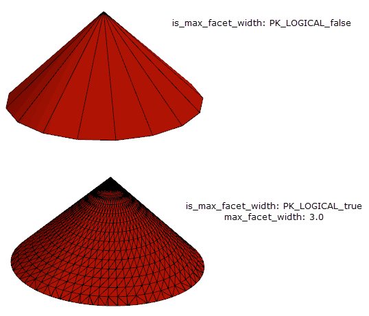
Figure 84-3 Controlling the facet sizes
If
is_max_chord_length
is PK_LOGICAL_true and
max_chord_length
is a positive value, this value will control the maximum length of any facet edge which represents part of an original edge.
You can control the distance and angular tolerance using the
distance_tolerance
and the
angular_tolerance
options.
If
is_distance_tolerance
is PK_LOGICAL_true and
distance_tolerance
is a positive value in model units, then this value controls the maximum chordal distance between a facet edge and its original edge and the minimum distance between the mid-plane of a facet and its original face entity.
If
is_angular_tolerance
is PK_LOGICAL_true and
angular_tolerance
is a positive value in model units this value is used to control the maximum angle in radians between a facet chord and its original edge. It also controls the maximum angle in radians allowed between the surface normals at any two positions on the surface that lie within the facet boundary.
You can use the
partial_conversion
option to control the behaviour if some of the faces or edges on the original body fail to convert to facet geometry.
It takes the following values:
|
If any of the faces or edges on the original body fail to convert to facet geometry then PK_ERROR_failed_to_facet is returned and the operation fails. Default |
|
|
|
Note: Topologies with no geometry in the original body are not converted during the operation and do not appear in the returned Parasolid report. |
Parasolid has a number of functions that allow you to create or remove facet data and standard forms that can be used to create polylines and meshes. In addition, facet geometry can be attached or detached from supplied model topology to create the desired body. It is recommended that you attempt to repair any defects on a mesh before any topology is added: see Chapter 86, “Checking and Repairing Mesh Data”, for more information.
PK_MESH_make_bodies creates bodies from mesh data. It does this by analysing the mesh to find out how many disjoint components are present and to find the laminar mesh fins that are used to build edges and their respective polylines. The mesh is attached to faces on the new body or bodies, polylines are attached to edges and points to vertices.
If a mesh has no laminar mfins and encloses a watertight volume, the resulting body will be topologically spherical as Parasolid will not add any additional topology automatically.
PK_MESH_make_bodies takes the following options:
PK_MTOPOL_make_meshes creates a mesh using a collection of mesh topologies (mtopols) either from the same mesh or from multiple meshes. You can either supply all the mtopols needed to create the mesh, or you can choose to supply a small set of mfacets from which a mesh can be created as described in the following sections:
PK_MTOPOL_make_meshes takes the following options:
|
A callback function of type PK_MTOPOL_select_cb_t used to determine how to propagate from an initial seed mtopol. See Section 84.4.2.1, “Creating a mesh from a small set of mfacets” for more information. |
|
|
Context information required by |
|
|
The class type of the input mtopol used in |
|
|
Whether to create a mesh either from the mfacets set selected by
See Section 84.4.2.1, “Creating a mesh from a small set of mfacets” for more information. |
|
|
Whether mfacets in the newly created mesh(es) should be tracked back to their respective mfacets in the input meshes. It takes the following values:
|
|
|
Whether mvertices in the newly created mesh(es) should be tracked back to their respective mvertices in the input meshes. It takes the following values:
|
|
|
A callback function of type PK_MTOPOL_map_cb_f_t used to return tracking information to the user. Default: NULL |
|
|
The number of elements in the |
|
|
The faces attached to the supplied mtopols. When using this option, all faces must be from the same body. See Section 84.4.2.2, “Creating meshes using mfacets from multiple meshes” for more information. |
|
|
Controls the sense of the resultant mesh. See Section 84.4.2.2, “Creating meshes using mfacets from multiple meshes” for more information. |
|
|
Indicates whether to use all the mfacets from the supplied faces. See Section 84.4.2.2, “Creating meshes using mfacets from multiple meshes” for more information. |
Both PK_MTOPOL_make_meshes and PK_MFACET_find_perimeters have options to allow you to create a mesh using a smaller set of mfacets. Using the callback function defined by
select_cb,
this set of mfacets act as seeds that propagate outwards into the adjacent mfacets to create a mesh. Depending on the value of
select_mtopol_class
,
select_cb
will take either an mfacet or an mfin and specifies whether to propagate to the adjacent mfacet or the mfacet of the adjacent mfin respectively as illustrated in
Figure 84-4.
As shown in
Figure 84-4, mfacet A is part of the selected set of mfacets and mfacet B is an adjacent mfacet that has not been selected. If
select_mtopol_class
is set to PK_CLASS_mfin, the
select_cb
function specifies propagation across the mfin and into its mfacet. If
select_cb
is set to PK_CLASS_mfacet, the
select_cb
function specifies propagation into the adjacent mfacet.
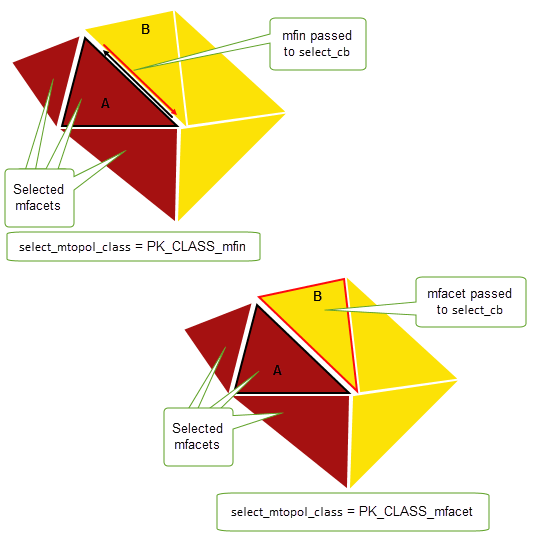
Figure 84-4 Different class types that can be passed to the callback function
This functionality may be useful when deploying an algorithm to infer model topology from the facet topology of the mesh, or when you require a subset of facet topology from a large mesh whose facet elements satisfy a certain criterion, such as distance from a given point.
If you are creating meshes from multiple meshes, you need to specify the following in PK_MTOPOL_make_meshes:
faces
option.
senses
option.
contributions
option.
Note: If
select_type
is PK_selector_type_exclude_c and
contributions
is PK_MTOPOL_selection_all_c, mtopols from the associated faces will not be used. |
You can create classic geometry directly from a mesh using PK_MESH_make_surf_trimmed. This function converts mesh data from a single mesh into a single trimmed surface as illustrated in Figure 84-5.
This function takes the following options:
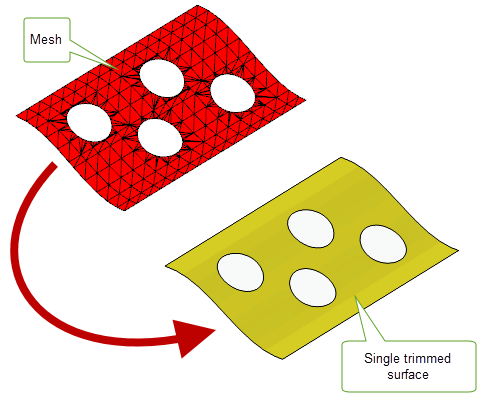
Figure 84-5 Creating a trimmed surface from a single mesh
Use PK_SURF_make_sheet_trimmed to create topology for the resulting trimmed surface:
surf
and
trim_data
returned by PK_MESH_make_surf_trimmed to PK_SURF_make_sheet_trimmed.
sense
in PK_MESH_make_surf_trimmed is PK_LOGICAL_false, then pass the body returned by PK_SURF_make_sheet_trimmed to PK_BODY_reverse_orientation.|
Note: PK_MESH_make_surf_trimmed does not support the creation of periodic B-surfaces. |
For some modelling functions, if their input bodies contain facet geometry only, you may control whether any resulting bodies have facet geometry only, or a mixture of classic and facet geometry. These functions use the
keep_as_facet
option described in the following table:
The
keep_as_facet
option is available in the following functions:
|
See Section 37.2.6.1, “Preventing mixed bodies”, for more information. |
|
|
See Section 36.3.2, “Specifying options”, for more information. |
|
|
See Section 55.4, “Options for global and local sectioning”, for more information. |
|
|
See Section 55.4, “Options for global and local sectioning”, for more information. |
| <<< Facet Model Structure | Chapters | Creating PSM Data From Foreign Facet Data >>> |