
 |
Creating Profiles |
| <<< Introduction To Profiling and Surfacing | Chapters | Creating Extruded Bodies >>> |
A profile is a general term for a simple zero-, one- or two-dimensional body that is subsequently used to create new bodies with free-form geometry. Creating profiles is an important technique in solid modeling, and Parasolid provides functionality to make it simple.This chapter describes how you can create profiles from a set of curves, by creating sheet bodies directly or from existing entities.
This chapter contains the following sections:
The most basic way of creating a profile is to build it piecemeal by imprinting a series of curves:
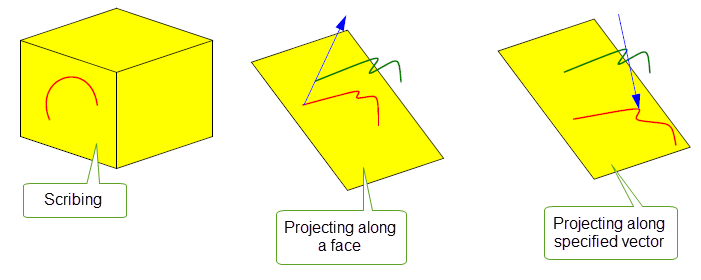
Figure 36-1 Imprinting curves by scribing and projecting
Parasolid provides a range of functionality to let you create primitive sheet bodies such as circles, polygons and rectangles.
Parasolid provides tools to create a wire profile from a set of existing edges or curves in a single operation, and to turn a closed wire into a sheet body if required.
You can use PK_BODY_make_curves_outline, PK_BODY_make_persp_outline and PK_BODY_make_spun_outline to create a profile from the outline of one or more solid or sheet bodies. PK_BODY_make_curves_outline also allows you to create a profile from the outline of one or more wire or general bodies.
|
Note: If you are creating a profile from a general body, it cannot contain any zero dimensional components. |
Parasolid supports the following types of outlines:
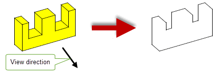
Figure 36-2 Creating outline curves for a body
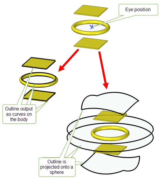
Figure 36-3 Creating a perspective outline for a body
|
Note: You cannot create a spun outline from sheet bodies: only solid bodies can be used. |
For an example of this functionality, see the code example in the
C++\Code Examples\Modelling\Outline
And
Spun
Outline
folder, located in
example_applications
in your Parasolid installation folder.

Figure 36-4 Creating spun outlines for a body
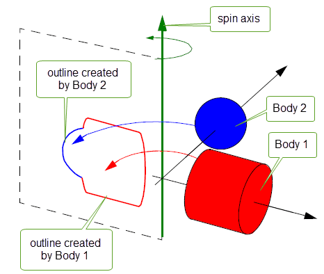
Figure 36-5 Creating spun outlines for two bodies
Both outline curves and spun outlines share a number of properties, as follows:
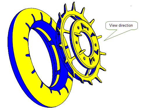
Figure 36-6 Shadow curves on a set of bodies
PK_BODY_make_curves_outline, PK_BODY_make_persp_outline, and PK_BODY_make_spun_outline receive the following arguments:
n_bodies |
|
bodies |
An array of length |
transfs |
An array of length
|
view_direction eye_position spin_axis |
|
options |
Options for the call to PK_BODY_make_curves_outline, PK_BODY_make_persp_outline,or PK_BODY_make_spun_outline. See Section 36.3.2, “Specifying options” for details. |
PK_BODY_make_curves_outline, PK_BODY_make_persp_outline and PK_BODY_make_spun_outline can output results in their returned arguments or in the Parasolid Report. See Section 36.3.9, “Reporting function results” for more information.
PK_BODY_make_curves_outline and PK_BODY_make_spun_outline return the following arguments:
n_curves |
|
curves |
|
intervals |
|
topols |
The topological entities from the original |
outlines |
A set of integers that indicates which curves belong to which outlines. See Section 36.3.7, “Differentiating between several outlines” for details. |
curve_tolerances |
A tolerance for each returned curve that indicates the accuracy to which each curve represents the outline. |
max_separation |
The largest gap between ends of adjacent curves in the outline. |
The returned
curves
,
intervals
,
topols
,
outlines
, and
curve_tolerances
are all of length
n_curves
.
PK_BODY_make_persp_outline returns the following arguments:
result |
Structure containing status information and an array of the outlines generated. |
tracking |
Information on the edges and faces that generated the outline curves. See Section 36.3.6, “Returning topological entities” for more information. |
Any new curves that are created as a result of the function call are attached as construction geometry to the original bodies. Alternatively, you can choose to create a body from the returned curves. See Section 36.3.5, “Returning wire or sheet bodies”, for information on how to do this.
You can set a number of options when creating outline curves, perspective outlines, and spun outlines, using the associated PK_BODY_make_curves_outline_o_t, PK_BODY_make_persp_outline_o_t, and PK_BODY_make_spun_outline_o_t options structure respectively. These options structures contain the following options:
|
Whether to output curves as 3-dimensional curves, or project the curves onto a surface. This is one of:
Default: PK_outline_project_no_c. Note: When used in PK_BODY_make_curves_outline or PK_BODY_make_spun_outline, the value must be set to either PK_outline_project_no_c or PK_outline_project_plane_c. |
|
Accuracy of the curves generated by PK_BODY_make_curves_outline. Default: 1.0e-06. |
want_body |
Whether to additionally create a body that is constructed from the set of outline curves returned by the function. Default: PK_LOGICAL_false. See Section 36.3.5, “Returning wire or sheet bodies”, for more information. |
body_dimension |
Whether to request a wire body or sheet body, when |
|
Whether or not to return a resulting body containing facet geometry only, or a mixture of facet and classic geometry. See Section 84.6, “Creating a mixture of facet and classic geometry”, for more information. Note: This option only applies when
body_dimension
is PK_TOPOL_dimension_2_c. |
|
Whether the results of the function are output as returned arguments or through the Parasolid Report. See Section 36.3.9, “Reporting function results” for more information. Default: PK_results_output_return_c. |
PK_BODY_make_curves_outline_o_t and PK_BODY_make_spun_outline_o_t contain the following options:
|
A point through which the plane being used to project the curves passes. Default: (0, 0, 0). |
|
Whether or not to return topological entities in the See Section 36.3.6, “Returning topological entities” for information on what topological entities are returned. |
edge_on |
Whether to create outlines of wire components or sheet components that are edge-on when viewed in a specified direction. It takes one of the following values:
Default: PK_outline_edge_on_none_c. Note: This option is only available in PK_BODY_make_curves_outline. |
update |
Update switch to maintain consistency when rebuilding models built in older versions of Parasolid. See Section 36.3.8, “Update control”, for more information. |
invisible |
Whether to create invisible outlines. It takes one of the following values:
The effect of this option is shown in Figure 36-9. Default: PK_outline_invisible_no_c. Note: Information on invisible outlines is only returned when
results_output
is set to PK_results_output_report_c. See Section 36.3.9, “Reporting function results” for more information. This option is only available in PK_BODY_make_spun_outline. |
n_exclude_faces |
The number of faces to be excluded from the outline. Note: This option is only available in PK_BODY_make_spun_outline. |
exclude_faces |
An array of faces to be excluded from the outline. Each set of excluded faces must be bounded by sets of edge-on faces and must not be winding with respect to the spin axis. In addition, the resulting wound from excluding the faces from the spun outline must be healable by extending adjacent section curves. The effect of excluding faces from a spun outline while creating both visible and invisible outlines is shown in Figure 36-10. Note: This option is only available in PK_BODY_make_spun_outline. |
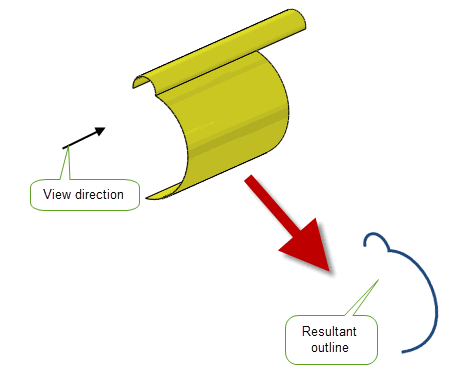
Figure 36-7 Creating an outline of an edge-on sheet body when the
edge_on
option is set to PK_outline_edge_on_all_c

Figure 36-8 Creating an outline of a non-edge-on sheet and wire inputs when the
edge_on
option is set to PK_outline_edge_on_both_c_

Figure 36-9 Creating invisible outlines of a body with two blind holes and one through hole using the
invisible
option in PK_BODY_make_spun_outline
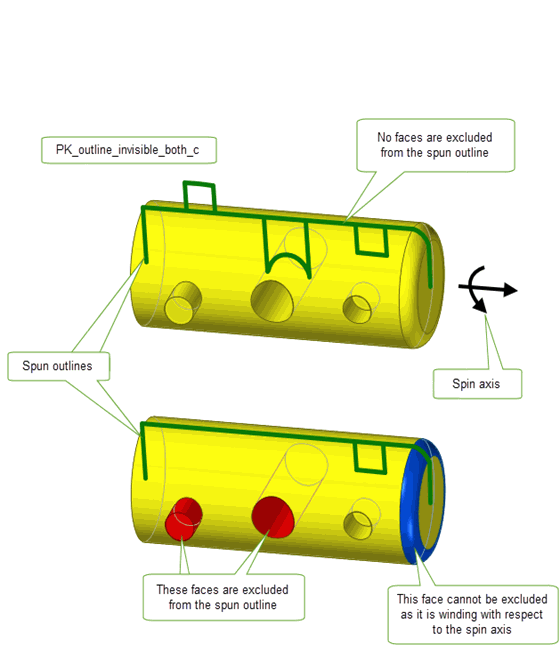
Figure 36-10 Creating invisible outlines of a body and excluding multiple sets of faces using the n_exclude_faces and exclude_faces options in PK_BODY_make_spun_outline
PK_BODY_make_persp_outline_o_t has the following options:
|
A location vector that defines the surface that the outlines are projected onto. Default: (0 0 0). |
|
|
A direction vector that defines the axis direction of the cylinder that the outlines are projected onto. Note: This option is ignored if
project
is PK_outline_proiect_plane_c or PK_outline_project_sphere_c. |
|
|
Whether to shrink perspective outline curves that are projected onto a plane. See Section 36.3.3, “Shrinking perspective outline curves” for more information. Default: PK_scale_factor_1x_c |
|
|
Whether to return tracking information for the resultant outline curves. Default: PK_LOGICAL_false. |
|
|
The types of viewing ranges in 3D space that are used to clip the outline curves. See Section 36.3.4, “Clipping perspective outline curves” for more information. Default: PK_persp_clipping_no_c |
|
|
The viewing angle. See Section 36.3.4, “Clipping perspective outline curves” for more information. |
|
|
The view direction. See Section 36.3.4, “Clipping perspective outline curves” for more information. |
|
|
The spin angle between 0 and pi. See Section 36.3.4, “Clipping perspective outline curves” for more information. |
|
|
The spin axis direction. See Section 36.3.4, “Clipping perspective outline curves” for more information. |
|
|
A sheet or solid body used to clip the outline curves. See Section 36.3.4, “Clipping perspective outline curves” for more information. |
The
project_scale
option allows you to shrink outline curves projected onto a plane by a specified value. This functionality can be useful when projecting the outline of large input bodies (that lie within the size box) onto a plane where the result outlines would be projected outside of the size box. By specifying a value in
project_scale
, you can shrink the resultant outline curves by that value so they will fit within the size box. For example, if you set
project_scale
to PK_scale_factor_10x_c, a scaling factor of 10 is used and the size of the perspective outline is reduced by a factor of 10.
If
project_scale
is set to PK_scale_factor_1x_c, no rescaling is applied.
Note: When using this option,
project_location
defines the scaling centre. |
PK_BODY_make_persp_outline has a number of options that enable you to clip the outline curves so that only those curves that fall within a specified range are generated. These options are discussed in this section.
The
clipping
option specifies the various types of viewing ranges that you can use to clip the outline curves. The types of viewing ranges are defined using various combinations of the
view_angle
,
view_direction
,
spin_angle
,
spin_direction
, and
clipping_body
options. These are as follows:
|
Do not clip the outline curves (Default) as illustrated in Figure 36-3 |
|
|
Clip the outline curves so those generated lie within a cone.
With this viewing range, the apex of the cone is the |
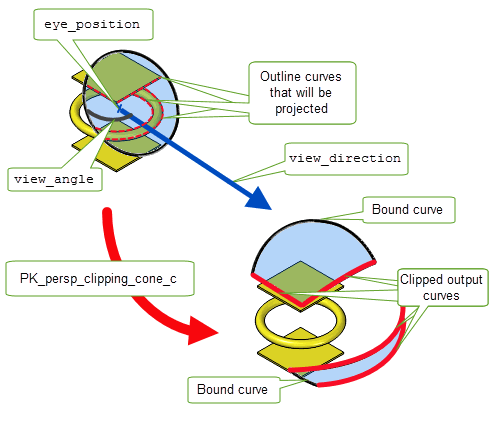
Figure 36-11 Example of clipping outline curves using PK_persp_clipping_cone_c
|
Clip the outline curves to lie within a spherical sector that is bounded by a pair of spherical cones.
With this viewing range, the apex of the cones is the |
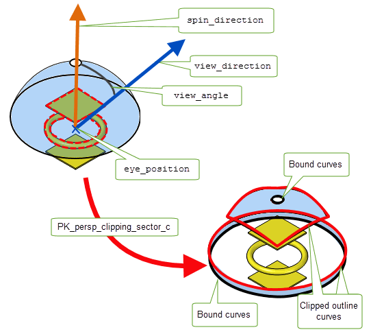
Figure 36-12 Example of clipping outline curves using PK_persp_clipping_sector_c
|
Clip the outline curves to lie within a wedge.
The apex of the wedge is defined by the |
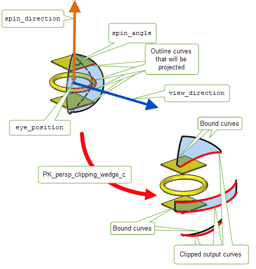
Figure 36-13 Example of clipping outline curves using PK_persp_clipping_wedge_c
|
Clip the outline curves to lie within a spherical pyramid.
The apex of the pyramid is defined by the |
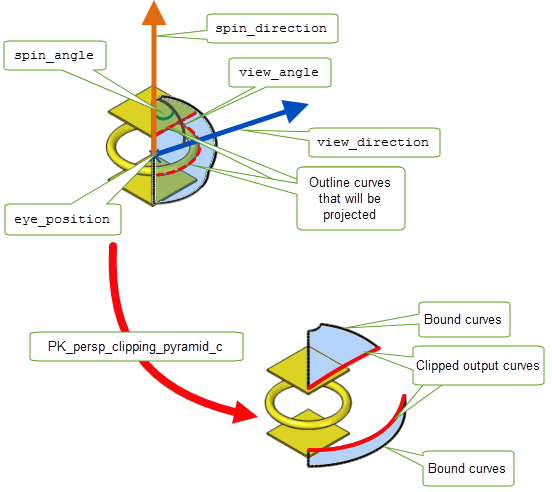
Figure 36-14 Example of clipping outline curves using PK_persp_clipping_pyramid_c
|
Clip the outline curves to lie within the generalised cone formed by the outlines of the |
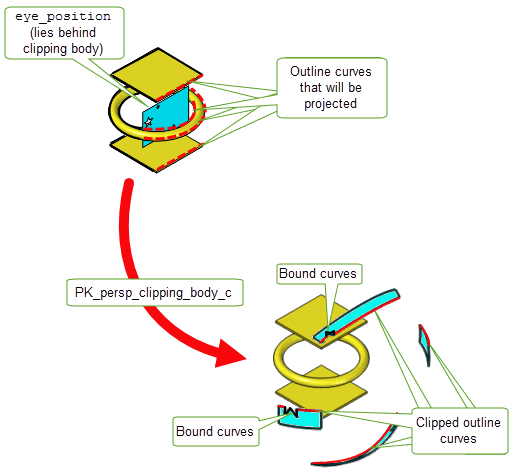
Figure 36-15 Example of clipping outline curves with a clipping body
PK_BODY_make_curves_outline and PK_BODY_make_spun_outline both return the curves that form the requested outline, together with tolerance and interval information for those curves.Usually, however, it is more convenient to access those curves via a body. PK_BODY_make_curves_outline, PK_BODY_make_persp_outline, and PK_BODY_make_spun_outline functions have the
want_body
and
body_dimension
options that allow you to do this.
If
want_body
is PK_LOGICAL_false, Parasolid attaches the outline curves to the appropriate input bodies as construction geometry.If
want_body
is PK_LOGICAL_true, Parasolid creates a single body that contains all the curves that formed the requested outline. The returned curves are attached to this body as principal geometry. Only one body is created per set of outlines; if the generated outline contains multiple loops of curves, then this body may consist of disjoint components.
The body is not explicitly returned by either PK_BODY_make_curves_outline or PK_BODY_make_spun_outline. To access it, you should call PK_CURVE_ask_part using any of the returned
curves
as input.
By default,
want_body
is PK_LOGICAL_false: you should only set it to PK_LOGICAL_true if
project
is
not PK_outline_project_no_c.
You can also control the type of body created using the
body_dimension
option, which takes the following values:
|
Requests Parasolid to create a wire body (i.e. a body that has a maximum dimension 1) that contains the returned curves. This is the default. |
|
|
Requests Parasolid to create a sheet body (i.e. a body that has a maximum dimension 2) that contains the returned curves. Note: If using this value with the
edge_on
option,
edge_on
must be set to PK_outline_edge_on_none_c. |
Figure 36-16 shows an example where outline curves are created for a disjoint body and attached to a new body. The resulting body is also disjoint, whether a wire body or a sheet body is requested.
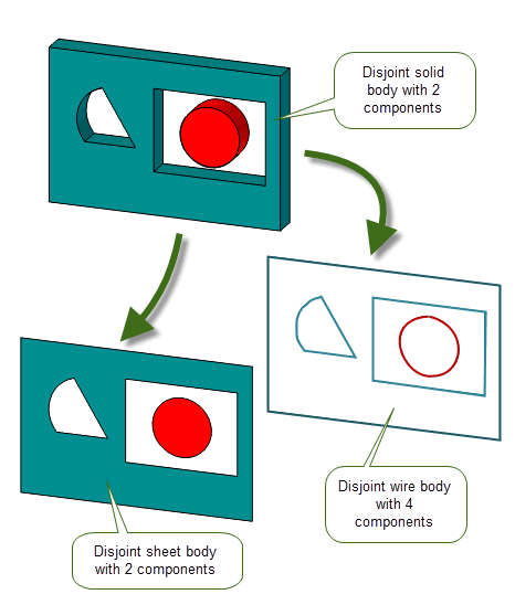
Figure 36-16 Creating disjoint outline curves from a disjoint body
By contrast, Figure 36-17 shows an example where outline curves are created for a non-disjoint body. In this case, if a wire body is requested, the result is disjoint.
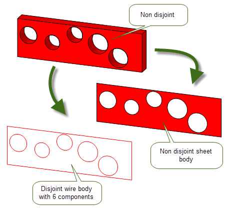
Figure 36-17 Creating disjoint outline curves from a non-disjoint body
Depending on the nature of the input body and the
view_direction
used in PK_BODY_make_curves_outline and PK_BODY_make_persp_outline, it is possible, when requesting a wire body (
body_dimension
is PK_TOPOL_dimension_1_c) that the body created is general, even if the input body is not general.
Figure 36-18 shows an example where the two components of a disjoint body, when viewed from a particular view direction, cause the resultant outline to form a general body.
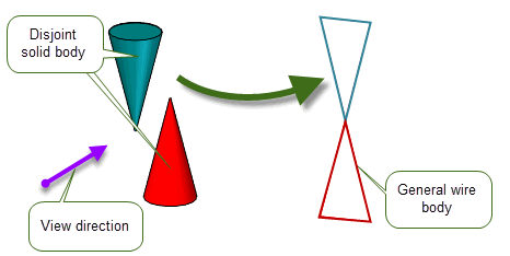
Figure 36-18 Creating a general outline curves body
As well as the outline curves themselves, PK_BODY_make_curves_outline and PK_BODY_make_spun_outline can also return, in
topols
, the topological entities from the original bodies that were used to create each curve. The entity that is returned for each curve depends on how the curve was derived:
This is illustrated in Figure 36-19, which shows an outline consisting of 4 curves.
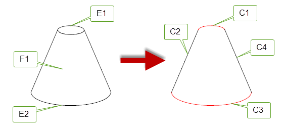
Figure 36-19 Topological entities used to create outline curves
The topological entities that are returned for each curve in the outline are shown below. Note that the face F1 is returned for both C2 and C4, since these curves are created from the silhouette of F1.
If you are using PK_BODY_make_persp_outline, the equivalent information is returned in the
tracking
argument if
want_tracking
is PK_LOGICAL_true.
The curves returned by PK_BODY_make_curves_outline, PK_BODY_make_persp_outline, and PK_BODY_make_spun_outline often make up more than one outline, as shown in
Figure 36-20. This may happen when you create outlines of several overlapping bodies, as shown in the figure, or when you create outlines of a body containing holes. When several outlines are returned, use the value of
outlines
to find which curves make up each outline.

Figure 36-20 Returning several outlines from PK_BODY_make_curves_outline or PK_BODY_make_spun_outline
Suppose, for example, that three outlines were returned, consisting of 2, 7, and 2 curves respectively (as in
Figure 36-20). In this case, the value of
outlines
would be
This indicates that the first 2 curves returned form one outline, the next 7 form another outline, and the last 2 form a third outline.
|
Note: When several outlines are returned, the order in which the outlines themselves are returned is undefined, so it is not possible to tell which outline is which. |
If you are using PK_BODY_make_persp_outline,
outlines
information is returned in the
result
structure.
If your application relies on reproducing behaviour when updating models built using earlier versions of Parasolid, you should use the
update
option to preserve old behaviour and help eliminate differences in rebuild results. This option lets you disable some curves and spun outline enhancements that have been added at different Parasolid versions. Doing this ensures that PK_BODY_make_curves_outline and PK_BODY_make_spun_outline give the same results in the latest version of Parasolid as in earlier versions. See PK_outline_update_t in the
PK Interface Programming Reference Manual for more information on this
update
option.
|
Note: The default value is PK_outline_update_default_c which uses all appropriate outlining enhancements. Setting to a non-default value disables all appropriate outlining enhancements. |
You can use the
results_output
option to choose whether to output the results of the operation in the returned arguments of PK_BODY_make_curves_outline, PK_BODY_make_persp_outline and PK_BODY_make_spun_outline, or in the Parasolid Report.
Outputting results as a report allows Parasolid to provide more information than is available through the function’s returned arguments. For a successful operation, the report provides a richer set of tracking information. For a failing operation, the details in the report allow you to return enhanced diagnostic information on the failure.
This option has the following values:
|
The results of the operation are output in the respective function’s returned arguments. Default. |
|
|
The results are output in the Parasolid Report via a record of type PK_REPORT_record_type_3_t. If the function succeeds with no errors, the outline results are returned in a record with Note: If you choose to return information via the Parasolid Report, the function’s returned arguments will be empty. See Chapter 11, “Using Reports” for more information on the Parasolid Report mechanism. |
| <<< Introduction To Profiling and Surfacing | Chapters | Creating Extruded Bodies >>> |