
 |
Sheet Modeling |
| <<< Wire Modeling | Chapters | Sewing and Knitting >>> |
Parasolid provides specific functionality for some sheet modeling operations, and techniques that allow solid modeling functions to be used for sheet modeling. This chapter covers:
The boolean operation of sewing sheet bodies together is explained in Chapter 46, “Sewing and Knitting”.
Trimming operations are often performed using booleans (see Chapter 52, “Manifold Booleans”). However, there are circumstances where it can be more efficient to trim a multi-faced sheet body by first imprinting an entity (curves, faces or a plane) on to the body, and then trimming to the edges on the sheet body that were the result of the imprinting process. This is explained in Section 45.3 and Section 45.3.
Information on modeling operations which can be applied to wire bodies is contained in Chapter 44, “Wire Modeling”.
You can use PK_FACE_make_sheet_bodies to create one or more sheet bodies from a collection of faces. This function contains the following options:
allow_disjoint |
Return disjoint components as either a single disjoint body or several bodies. |
make_from |
Whether to make a sheet body (or bodies) from copies of the input faces, as illustrated in Figure 45-1, or from the original input faces themselves,as illustrated in Figure 45-2. |
transfer_attribs |
Whether the sheet bodies inherit attributes from the topology used to create the sheet bodies. |
transfer_groups |
Whether to transfer or copy specified groups to the new sheet body (or bodies). |
track_edges |
Whether to return edges from the resulting sheet bodies in the tracking data. Default: PK_track_edges_no_c |
track_vertices |
Whether to return vertices from the resulting sheet bodies in the tracking data. Default: PK_track_vertices_no_c |
|
Note: If you supply faces from different bodies to this function, you should ensure that they do not intersect. If the supplied faces intersect, PK_FACE_make_sheet_bodies may create an invalid body. |
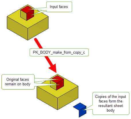
Figure 45-1 Creating a sheet body from copies of the input faces
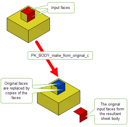
Figure 45-2 Creating a sheet body from the original input faces.
Trimming is performed using PK_BODY_trim. To be successful, this must divide the body into at least two sets of faces. PK_BODY_trim takes the following arguments:
The supplied
edges
and
faces
must all belong to the supplied
body
.
Should the trim operation fail, PK_BODY_trim_gap_analysis can be used to determine where the gaps of size less than the supplied tolerance exist, and the vertices bordering on these gaps are returned to enable corrective actions to be taken.
In this first example, a sheet body - created from a B-surface - is trimmed to an area resulting from the projection of two B-curves in a specified direction.
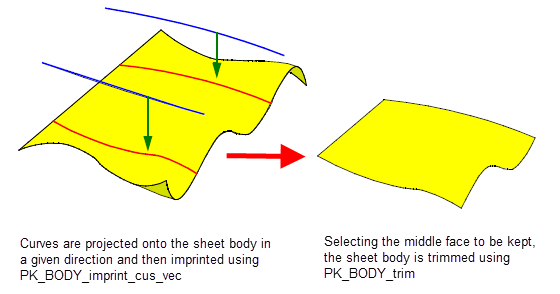
Figure 45-3 Trimming a sheet body to curves projected in a given direction
In this following example, a sheet body (created from a part of a cylinder) is trimmed to an area resulting from the projection of the circle down the face normal of the sheet body. This resulting face on the sheet body is selected not to survive the trim operation, effectively doing a pierce operation on the sheet body:
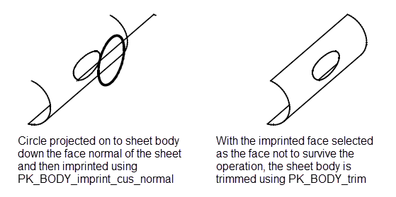
Figure 45-4 Trimming a sheet body using a circle projected down the face normal of the sheet body
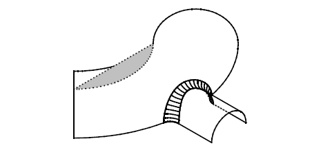
By using the solid modeling blend functions for applying, fixing, enquiring and checking blends it is possible to blend edges of sheet bodies which meet at the boundary of the sheet body. Parasolid constructs appropriate edge geometry at the ends of the blend. The blend type can be rolling-ball, variable-radius or chamfer.
Parasolid’s face-face blending functionality can be used to blend between disjoint and overlapping faces. In the following example face-face blends are applied sequentially to a set of sheet bodies, that have faces with taper angles, to form a single sheet body as follows:
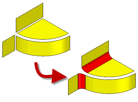
Figure 45-6 Joining pairs of sheets
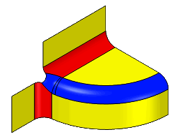
Figure 45-7 Using a third face-face blend to create the single sheet body
For further information on Face-Face blending, see Chapter 77, “Face-Face Blending”.
To blend vertices on sheet bodies use PK_VERTEX_make_blend.
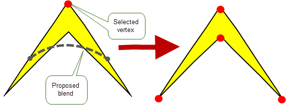
Figure 45-8 The proposed blend would create an invalid body, so the blend is not created
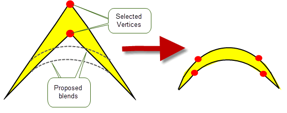
Figure 45-9 By selecting both vertices the final body is valid and the blends can be created
It is permissible for two blends to be sufficiently large that they meet and exclude one of the original edges providing that the blends do not overlap. For example, it is possible to make a circle by blending the four vertices of a square.
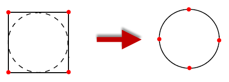
Figure 45-10 Blending four vertices of a square to create a circle

Figure 45-11 Blending a vertex with a radius that is equal to the distance to the next vertex
If the local checking option is ON the body is checked after the blending has been carried out. In the case of a planar body the altered body is valid, but for a non-planar body local checking may return that the altered body is invalid.
A sheet body can be thickened to form a solid body using PK_BODY_thicken_3. For a complete description of this functionality, see Chapter 60, “Thickening”.
Providing that the relevant face of a sheet body has a surface attached to it, then the following operations can be carried out on it:
The surface of a sheet can be tweaked to a new surface, which must be of the same type as the original surface, using PK_BODY_embed_in_surf. During this operation the parameter space representation of the edges is maintained.
|
Note: This functionality does not offer support for facet geometry. |
If the edge curve is of type PK_CLASS_spcurve or a constant parameter curve of the surface of the face then it is transferred to the new surface. All other types of edge curves are converted to SP-curves before being transferred to the new surface. During this conversion, edges may need to be split at surface discontinuities.
| <<< Wire Modeling | Chapters | Sewing and Knitting >>> |