 |
Viewing Models |
|
Contents
[back to top]
3.1 Introduction
This chapter describes the different ways that you can change the way a model is viewed in PS/Workshop. It describes how you can alter the direction and scale with which a model is viewed, and how you can alter the appearance of the model itself by using different types of view.
[back to top]
3.2 Altering view direction and scale
PS/Workshop offers a wide variety of tools to alter the direction from which a model is viewed, or the size of the image. Many of these tools are available directly from the toolbar.
[back to top]
3.2.1 Changing the direction of view
The following tools are available to alter the position that a model is viewed from:
|
Tool
|
Description
|
|
Rotate
|
To rotate the model, click  or choose
View > Modify > Rotate. Click and hold down the mouse button and move the mouse to rotate the model. All view modes, Wireframe, Wireframe plus silhouettes, Hidden Line and Shaded, are supported. View dependent silhouette calculation is suspended while the view is changing. It is recomputed when the mouse button is released.
|
|
Pan
|
To pan (scroll the current view of) the model, click  or choose
View > Modify > Rotate. Click and hold down the mouse button and move the mouse to pan the model.
|
[back to top]
3.2.2 Making the image smaller or larger
The following tools let you alter the size of the image in PS/Workshop:
|
Tool
|
Description
|
|
Zoom
|
To zoom in and out of the model, click  or choose
View > Modify > Zoom. To zoom in (make the image larger), click and hold the mouse button while moving the mouse up. To zoom out (make the image smaller), click and hold the mouse button while moving the mouse down.
|
|
Fit to Screen
|
To fit the entire model in the current window, click  or choose
View > Modify > Zoom to Fit. Select this icon to change the scale factor of the view so that the model fills the window in which it is displayed.
|
|
Zoom to Window
|
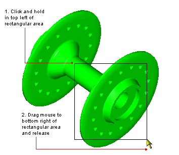
To zoom in to a specific area of a document, click  .Define the area of the document you want to view by clicking and holding down the mouse button in the top left corner and dragging the mouse to the bottom right corner. This zooms the display such that the area of the selected rectangle fills the window.
|

Figure 3-1 Selecting a rectangular area to zoom in to
[back to top]
3.2.3 Using standard views
A number of standard views are provided as menu commands in PS/Workshop. By choosing the relevant command in the
View > Standard Views submenu, you can switch instantly between the following view directions:
-
Isometric
-
Front
-
Back
-
Top
-
Bottom
-
Left
-
Right
[back to top]
3.3 Altering the appearance of the image
[back to top]
3.3.1 Altering the line width of edges
You can use the commands in the
View > LineWidth submenu to change the width of lines used to display edges in a model. Choose any value from 1 (the default) to 5.
[back to top]
3.3.2 Altering the way the image is rendered
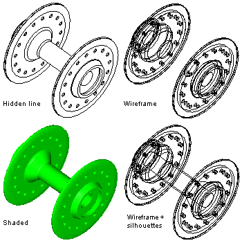
PS/Workshop provides a number of different ways of rendering a model on the screen. These are illustrated in Figure 3-2. If a part has a color attribute attached, then that color is used in the rendered image. Otherwise, the default body color, as specified in the PS/Workshop Options dialog, is used.
These colors, together with the document's background color, can be edited as described in Section 4.3, "Editing colors". Any model colors set within PS/Workshop are saved back as attributes to the model.
The following modes are provided in PS/Workshop:
|
Mode
|
Description
|
|
Wireframe
|
Click  or choose
View > Display > Wireframe to display the document in wireframe mode. This mode renders every edge on the model on the screen.
|
|
Wireframe + Silhouettes
|
Click  or choose
View > Display > Wireframe + Silhouettes to display the document in wireframe silhouette mode. Silhouette edges are edges that are implied by the view, rather than being real edges in the model itself. Their locations depend upon the view parameters and are computed as the view changes.
|
|
Hidden Line
|
Click  or choose
View > Display > Hiddenline to display the document in hidden line mode. This mode shows only those parts of real and silhouette edges that can be seen from the current view direction. Any part of an edge that is obscured by some other part of the model is not drawn. The results depend upon the view parameters and are computed as the view changes.
|
|
Shaded
|
Click  or choose
View > Display > Shaded to display the current model in shaded mode, as shown in Figure 3-2. Shaded mode can also be combined with either Wireframe or Wireframe + Silhouettes modes. These combined modes are known as
Dual Display Modes.
|

Figure 3-2 Wireframe, wireframe + silhouettes, hidden line, and shaded modes
[back to top]
3.3.3 Re-rendering the view
Zooming in on a portion of the model can produce a coarse screen image, especially if the model in the viewing area is curved. Click  to recompute a smooth view for the current view parameters.
[back to top]


 is selected, you cannot select any entities in the document. See Section 4.2, "Selecting entities", for information about selecting entities.
 to recompute a smooth view for the current view parameters.