Advanced Blending Functionality
In the most general sense, a blend is a transition surface between regions of a model. Standard blending, which is embedded within ACIS, offers blends to transition between faces, but ABL provides more options.
Advanced blending with ABL falls broadly into two categories:
- Edge sequence-following
-
Augments the range of face-face geometries available to standard blending.
- Entity-entity
- Provides a wholly general framework for blends between faces, edges, and vertices.
Note: The standard blending of the Blending Component provides some support for entity-entity blends to resolve certain difficult blending configurations. However, it does not provide the functionality for defining arbitrary entity-entity blends.
In ABL, variable radius blends may be defined with a more flexible range of radius functions and cross section shapes, and blends between faces and edges (entity-entity blending) may be performed.
ABL handles many more geometric and topological cases than standard blending and also provides many new blend shapes, augmenting the round and chamfer blends available in standard blending. However, the geometry classes (for example, new curve and surface types) needed for this functionality are implemented within the Kernel Component, because ACIS based applications that are not linked with ABL must be able to read, write, and evaluate (but not create) the geometries produced by advanced blending operations.
Refer to the Geometric Limitation on the Blend Radius topic.
Blend Cross Section
A blend surface between two entities has a characteristic shape, which is defined by its cross section. The cross section is a line in the blend surface, which connects the two entities being blended.
In standard blending, a blend surface bridges from one face to another face (for example, does not blend from a face to an edge or an edge to an edge). The cross section shape of the blend is seen by the shortest line along the blend surface from one face to the other.
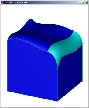
A round, or circular, cross section creates a pipe-shaped blend surface that is represented as a spline, in general, but under special circumstances is represented as a cylinder or a torus. In standard blending, the blend surface is tangent to each of the faces being blended, and the plane of the cross section is always perpendicular to both of the faces.
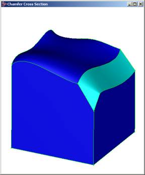
A chamfer cross section is a straight line which is controlled by offset distance parameters along each of the surfaces being blended. Under special circumstances, the blend surface is created as a plane or a cone.
In addition to the round and chamfer cross sections described above, the following cross section shapes are also available with ABL:
-
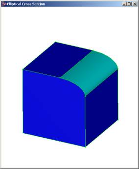
Elliptical
- Cross section shape is a rotated ellipse controlled by major and minor radius and rotation angle parameters.
-
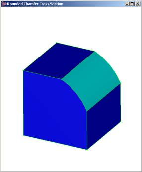
Rounded chamfer - Cross section is like a chamfer with a round bulge added. Like the chamfer, it is not tangent to the side surfaces. The bulge may be zero in order to create an ordinary chamfer.
-
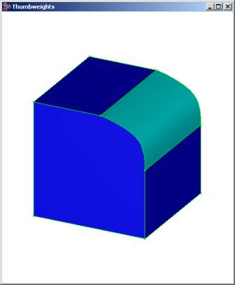
Thumbweights - The normally circular cross section can be given more or less bulge. The surface is still tangent to the side surfaces. Left and right thumbweights can be applied separately.
ABL provides geometry extensions that allow a variety of cross section shapes
beyond those available in standard blending.
In standard blending, the plane of the cross section is always perpendicular to both of the faces being blended, but with advanced blending, the plane of the cross section may be lofted to align with a given orientation.
Cross Section Radius
All types of blend surface cross sections are controlled by blend radius parameter values. Varying the parameter values at different positions along the blend surface allows the size of the cross section to change.
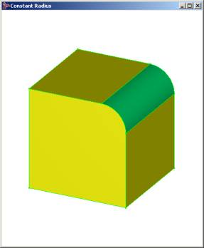
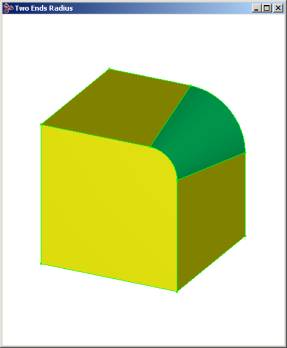
In standard blending, the blend radius may be either a constant radius value or an implicit variable radius across the blend, which is specified by providing two radius values at the ends of a smooth edge sequence.
In addition to these two radius specification methods, advanced blending offers the following methods:
-
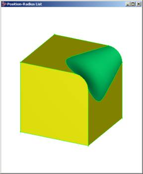
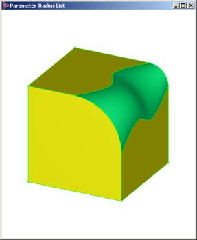
Radius specified by a series of radius values at arbitrary positions along the
blend.
-
Radius specified by a series of parameters along the defining curve for the
blend and corresponding radius values.
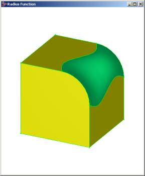
-
Radius specified by an arbitrary radius function.
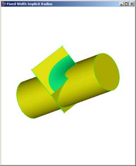
-
Radius varies implicitly, depending on the angle between the side faces, to
maintain a constant, or fixed, cross sectional width along the blend.
-
Radius varies implicitly, controlled by the specified holdline. A holdline is a
curve that lies in one of the support surfaces of the edge being blended. It
defines points of tangent contact between the support surface containing the
holdline curve and the blend surface, that is, it specifies the location for
the corresponding blend spring curve. The generated blend is a variable radius
blend where the radius value at any given point is defined by the holdline
curve. The radius of the blend is not specified explicitly but rather
calculated during the blend surface construction so that the blend surface
meets the support surface tangentially at the holdline. An example of a
holdline curve is shown in the first picture below (before blending has
occurred). Refer to the topic Holdline Blending
Sample for further details.
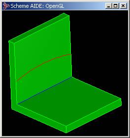
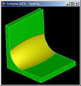
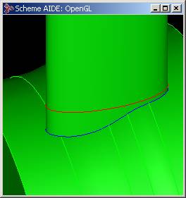
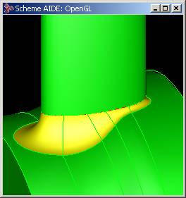
In the above example the holdline curve is in red and the edge to be blended is in blue (first picture). The resulting blend is shown in the second picture where the blend surface has been colored yellow. Another example is given below where a smoothly connected sequence of edges (in blue) is blended using a holdline (red).
Standard and advanced blending perform automatic smoothing of consecutive two-end functions. Additionally, advanced blending offers automatic stabilizing of discrete-valued radius functions. If parameter values are specified at a few locations, the resulting blend forces the parameter values to change smoothly between the specified points.
Topology
Standard blending supports blends between both faces that are adjacent to the blend edge (the blend is tangent to both faces) and has some limited support for blending faces and edges that are remote from the edge.
Advanced blending supports blends between:
- Both faces that are adjacent to an edge
- Two nonadjacent faces
- A face and an edge
- A vertex and a face
- A vertex and an edge
- Two edges
Mitering
Mitering is available only in standard blending and the geometry extensions provided by ABL. For entity-entity blends, the effect of mitering is only possible when distinct sequences can be fixed separately.
Automatic Transitions
With entity-entity blending, blend processing instructions are placed on the model to direct the automatic transition between blend types: from face-face to edge-face or from edge-face to face-face. This only applies to entity-entity blending.
Single Stepping
Blends using ABL may be produced in the same single-step manner as standard blending (using api_init_blend_ss, api_do_one_blend_ss, and api_concl_blend_ss).
Advanced Chamfering
Unlike Standard Chamfering, Advanced Chamfering provides the functionality for generating chamfers between any types of support surfaces. It also provides a method for specifying the chamfer ranges, which is more aligned with the way rolling ball blends are defined. In Advanced Chamfering the "ranges" specify the size of the balls that roll between the supports. If the ranges for the two supports are equal, a single ball with the radius equal to the ranges as shown below defines the contact points on both supports.
If the range values are different a ball with radius equal to range1 defines the contact point on one surface and a ball with radius equal to range2 defines the contact point on the other support. The chamfer cross section is then defined by a straight line drawn between the contact points on the supports as shown below.
Related topics:
[Top]
© 1989-2007 Spatial Corp., a Dassault Systèmes company. All rights reserved.