Offsetting a Wire Body
A body is the highest level topological entity. Solid bodies contain lumps, shells, subshells, faces, loops, coedges, edges, and vertices. Wire bodies contain wires, coedges, edges, and vertices. A simple list of edges can be used to create topology, and ACIS creates the other associated topological entities. The result is a model whose elements know about each other and the topology can be traced.
Many operations, such as wire offsetting, utilize the features of a body topological element and the inherent ability to trace its topology through adjacent wires and edges. This is why a (wire) body is required as input to these operations.
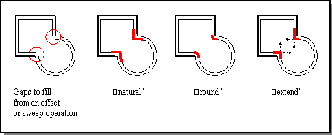
When a wire body is offset, sometimes gaps are created at certain junctures. Consider a wire body made up of a square and a circle that is offset towards the inside, as shown in the following figure. The resulting gaps can be filled as one of three types:
- Natural
- Extends the two shapes along their natural curves; for example, along the circle and along the straight edge, until they intersect.
- Round
- Creates a rounded corner between the two segments.
- Extend
- Draws two straight lines from the ends of each segment until they intersect.

Figure. Gap Fill Types
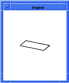
In the following example, four linear edges are created. Even though the end points of each edge were picked such that the edges appeared to intersect in a simple rectangular frame, the edges are independent and know nothing about one another. In other words, the edges are separate topological entities but are not part of a topology.
Offsetting occurs to the outside of a rectangle. By default, the wire offsetting fills the external gap using the round option. The result is a second wire body that is mostly rectangular except for rounded corners. The radius of the rounded corner is the wire offset amount. Refer to the previous figure.
Scheme Example
| ; Define the positions to be used (define my_point1 (position 0 0 0)) ;; my_point1 (define my_point2 (position 20 0 0)) ;; my_point2 (define my_point3 (position 20 10 0)) ;; my_point3 (define my_point4 (position 0 10 0)) ;; my_point4 ; Create edge 1 as a sine edge. (define my_linear1 (edge:linear my_point1 my_point2)) ;; my_linear1 ; Create edge 2 as a linear edge. (define my_linear2 (edge:linear my_point2 my_point3)) ;; my_linear2 ; Create edge 3 as a spline curve. (define my_linear3 (edge:linear my_point3 my_point4)) ;; my_linear3 ; Create edge 4 as a spline curve. (define my_linear4 (edge:linear my_point4 my_point1)) ;; my_linear4 ; Create a wire-body from a list of edges. (define my_wirebody (wire-body (list my_linear1 my_linear2 my_linear3 my_linear4))) ;; my_wirebody (define my_offset (wire-body:offset my_wirebody 5 "r")) ;; my_offset ; If desired, you could delete the original wire body; ; it is no longer needed. ;(entity:delete my_wirebody) ;; () ; Save the results to an output file. (part:save "tmpoffset1.sat") ;; #t |


Figure. Wire Body Offset
Some of the Scheme extensions related to wire bodies are:
- wire-body
-
Creates a wire body from a list of edges.
- wire-body:kwire
- Creates a planar wire specified by a sequence of points and bulge factors.
- wire-body:offset
- Creates a new wire by offsetting the given wire using offset and twist laws.
- wire-body:points
- Creates a wire body from a list of positions.
[Top]
© 1989-2007 Spatial Corp., a Dassault Systèmes company. All rights reserved.