
 |
Blending |
| <<< Building Bodies from Profiles | Chapters | Importing Foreign Data >>> |
In Parasolid, blending is used as a broad term that encompasses the following operations:
Filleting: replace edges with new blend faces that meet the adjoining faces of the original edges smoothly. You can fillet a sharp edge on a piece of wood by smoothing it off using sandpaper.
Chamfering: replace edges with new blend faces that have a linear cross-section, but do not meet the adjoining faces of the original edges smoothly. You can chamfer a sharp edge on a piece of wood by flattening it off using a plane.
Here, new surfaces are created between faces that are not necessarily connected, possibly joining bodies together in the process.
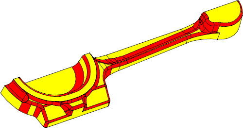
Figure 10-1 Blending in Parasolid
Parasolid provides three specific kinds of blending:
|
You supply a set of edges and Parasolid replaces them with new blend faces that meet the adjoining faces of the original edges. See Section 10.2. |
|
|
You supply two sets of faces (which need not be in the same body) and Parasolid creates new blend faces that lie between them. See Section 10.3. |
|
|
A specialized variation of face-face blending: you supply three sets of faces and Parasolid blends them, destroying the middle set in the process. See Section 10.4. |
Rather than being alternatives, these different types of blending have complementary strengths so that, when combined, they can work powerfully together.
During edge blending, Parasolid generates a series of faces to replace a set of specified edges in a body. These new faces meet the faces that were separated by the original edges, usually smoothly.
Edge blends are initially attached as attributes to the edges they will replace. Such blends are referred to as unfixed and can be modified or deleted.
Once defined, unfixed blends need to be fixed, incorporating them into the body and replacing the original edges.
This two-stage process allows Parasolid to resolve all the dependencies between multiple blends, such as that shown in Figure 10-2, which illustrates several intersecting blends of different radii. If a single-stage process was used, you would have to decide the order in which to apply multiple blends - a far from straightforward task!
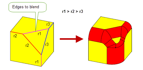
Figure 10-2 Creating complex intersecting blends using edge blending
Parasolid can create a variety of edge blends.
Parasolid provides many options to allow you to control the appearance of edge blends. Some of the most common are illustrated here.
Many blends cannot fit entirely inside one or both of the faces adjacent to the blended edge. Parasolid has a number of strategies that enable such blends to be fixed successfully. This process is known as creating blend overflows. Parasolid can create a number of different types of overflow, depending on the appearance you want and the exact configuration of the body in the region of the blend:
Parasolid can propagate blends along chains of tangent edges. You create a blend on one edge, and Parasolid will create a blend on the next edge if it meets the previous edge smoothly, continuing the chain of blends until a non-smooth edge is met.
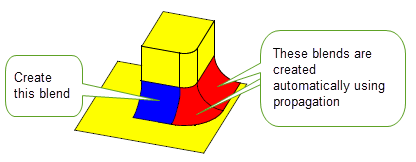
Figure 10-3 Propagating blends along smooth edges
Parasolid can limit an edge blend to stop it short of its natural finishing point, using either vertex or edge limits, or information about where blends would overlap each other.
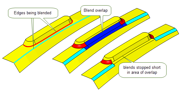
Figure 10-4 Creating blend limits for overlapping blends
These methods can be combined, as shown in Figure 10-5.
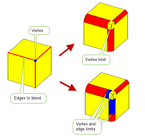
Figure 10-5 Blends limited at a vertex and along two edges
In addition, you can stop a blend short by capping it with either faces from the body, a plane, or a sheet body.
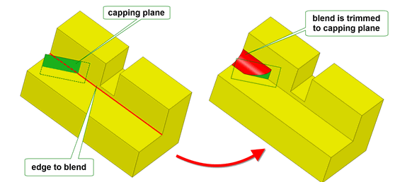
Figure 10-6 Trimming edge blends to a face in the body
Face-face blending differs from edge blending as follows:
To create a face-face blend, you choose two sets of faces, known as the left and right walls of the blend. You then define the blend in terms of the three independent properties shown in Figure 10-7.
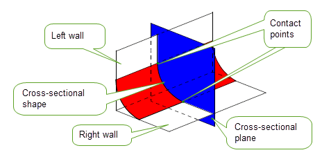
Figure 10-7 General definition of a face-face blend
You can create different face-face blend effects by varying the cross-sectional plane, as shown in Figure 10-8.
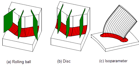
Figure 10-8 Creating blends with (a) rolling-ball, (b) disc and (c) isoparameter cross-sectional planes
Rolling-ball and disc blends are the most common form of cross-sectional plane. Isoparameter blends are specialized blends that are useful, for example, in turbine design.
Each cross-sectional plane in a blend contains two contact points, where the blend surface touches one of the blend walls. You can determine the position of these contact points in two ways:
The following types of blend are defined in terms of the size of the blend:
The following types of blend boundary, or holdline, can be defined. Parasolid creates blends that are bounded by these holdlines.
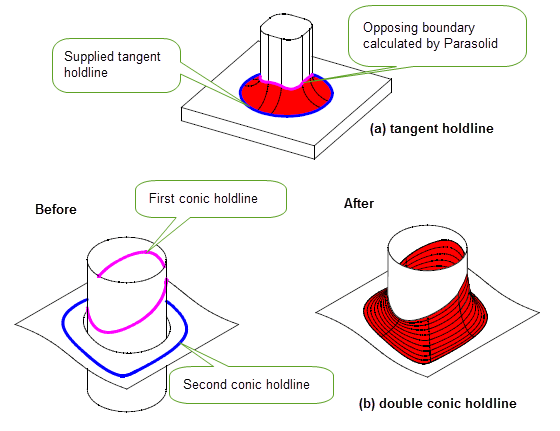
Figure 10-9 Supplying (a) tangent holdlines and (b) double conic holdlines
Holdlines can also be inverted, so that the blend is tangent to the face above the holdline rather than the face below, as shown in Figure 10-10.
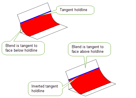
Figure 10-10 Using inverted holdline blends to control the tangency of a blend
You can also specify that a boundary should form a cliff-edge blend. As with edge blends, a face-face blend does not have to join the blend wall tangentially along the cliff edge.
Within a cross-sectional plane, you can control the shape of the blend (that is, the curve that joins the two contact points). Parasolid can create the following types of cross-sectional shape:
|
A circular, elliptical, hyperbolic or parabolic cross-section. |
|
|
A cross-section with the same curvature as the wall at each contact point. |
Parasolid provides different ways of trimming a face-face blend to its surrounding faces so as to produce the required final shape. Trimming may involve removing material from the blend surface, the walls, or both. The blend may be attached to the walls or created as a separate sheet body.
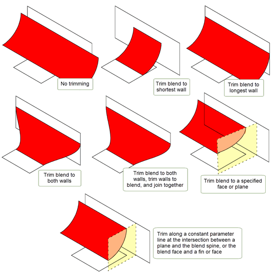
Figure 10-11 Trimming blend faces and blend walls
Parasolid can also trim blend walls using its imprint completion functionality as shown in Figure 10-12.
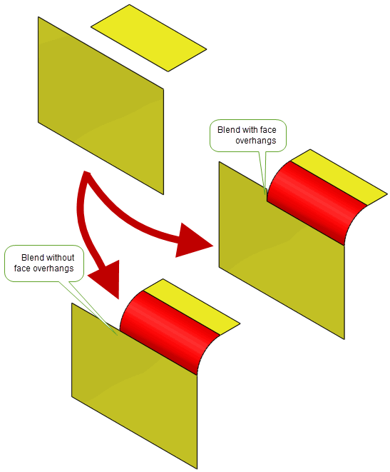
Figure 10-12 Trimming blend walls with imprint complete
As with edge blends, you can control a wide range of properties, such as propagation, behaviour at notches and so on.
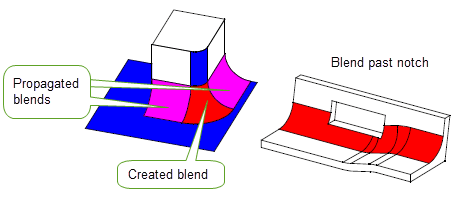
Figure 10-13 Propagation and notch behaviour in face-face blends
Rather than have Parasolid generate a blend surface, you can supply a surface to use in a blend operation. This is essential if your application makes use of specialized surface types that you want to use in conjunction with Parasolid’s face-face blending functionality.
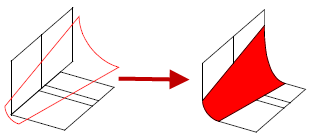
Figure 10-14 Blending faces with a user-supplied surface
It is possible to make a cliff-edge blend between a wall of faces and the edges of a wire body, known as a wire-face blend. There are a number of restrictions on the use of this functionality.
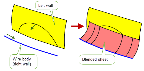
Figure 10-15 Example of a wire-face blend
In addition to standard face-face blending, you can create three-face blends (sometimes known as full round fillets), which are blends between three sets of faces.
Figure 10-16 shows a part containing a number of ribs, each of which has a three-face blend along the top.
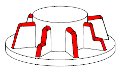
Figure 10-16 Blending three sets of faces
When creating three-face blends, three sets of walls are provided, rather than two. The resulting blend is trimmed and attached to the body automatically.
Three-face blending shares many options with face-face blending, as illustrated in Figure 10-17.
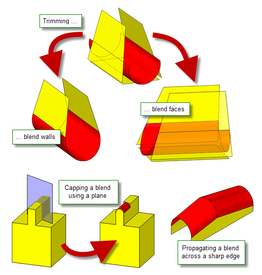
Figure 10-17 Options when creating three-face blends
| <<< Building Bodies from Profiles | Chapters | Importing Foreign Data >>> |