
 |
Introduction to Booleans |
| <<< Imprinting and Curve Projection | Chapters | Manifold Booleans >>> |
This chapter introduces you to the boolean operations available in Parasolid.
Boolean operations carried out when general topology is disabled in a session are referred to as manifold booleans. The input bodies to this type of boolean must be manifold bodies and any result bodies will also be manifold. Boolean operations on either general or manifold bodies that may result in general bodies are referred to as general booleans. It is assumed that you are familiar with the characteristics of the various body types, as explained in Chapter 15, “Body Types”.
|
Note: When performing boolean operations, we strongly recommend that you set local coordinate systems to be the same as the Parasolid coordinate system wherever possible. |
|
Note: This functionality offers partial support for facet geometry. See the
PK Interface Programming Reference Manual for more information. |
The basic boolean operations are analogous to mathematical set operations:
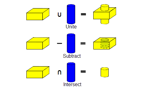
Figure 51-1 Basic boolean operations
For an example of this functionality, see the code example in the
C#\ExampleApplication.Net\Code
Examples\Modelling\Booleans
located in
example_applications
in your Parasolid installation folder.
This section introduces you to the terminology used in Parasolid’s boolean operations.
The operands of a boolean are called the target and the tool. The target of a boolean is the body you begin with, and the tool is the body you operate on it with. The target is modified by the tool, and the tool is deleted at the end of the operation. Parasolid preserves the tags of entities in the target as far as possible.
The following diagram shows the effect of swapping the target and tool of subtract:
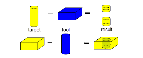
Figure 51-2 Target, tool and result bodies on boolean subtraction
This is important when we come to consider booleans between bodies of different types.
|
Note: If you are performing boolean operations on a single target with many tools, we recommend using a single multi-tool boolean. |
The rules for the persistence of tags described in Section 2.4.2, “Tags”, apply during boolean operations. However, tag persistence is disabled if normal attribute callbacks are registered and used. See Section 94.3, “Callback functions”, for more information.
A global boolean involves comparing all face pairs from the target and tool bodies.
Global booleans are performed using PK_BODY_boolean_2, which requires one target body, one or more tool bodies and an options structure. If more than one tool body is supplied, the union of overlapping tools is computed first and then the boolean between the target and the tools is performed. For intersect boolean operations, the intersection of one target and two tools is the intersection between the target and the result of uniting two tools rather than the mutual intersection between the three bodies.
For an example of this functionality, see the code example in the
C++\Code Examples\Modelling\Booleans\Global
folder, located in
example_applications
in your Parasolid installation folder.
|
Note: You can perform global booleans on any combination of manifold solid and sheet bodies, wire bodies and general bodies, so long as target and tools have no acorn vertices. For more information about performing booleans with general bodies, see Chapter 53, “General Booleans”. |
A local boolean involves comparing selected face pairs in the target and tool bodies. This form of boolean operation is quicker than a global boolean but does not guarantee topological consistency on the resulting bodies.
Local booleans are performed using PK_FACE_boolean_2, which requires one or more faces from a single target and tool body and an options structure. Local booleans using general bodies are not supported.
For an example of this functionality, see the code example in the
C++\Code Examples\Modelling\Booleans\Local
folder, located in
example_applications
in your Parasolid installation folder.
|
Note: Both PK_BODY_boolean_2 or PK_FACE_boolean_2 may return a status code of PK_boolean_result_failed_c following a failure, with a return code of PK_ERROR_no_errors from the function. In these cases, the model might be left in an invalid state. We therefore recommend that, if PK_boolean_result_failed_c is returned from a call to either of these functions, you roll back to a valid state of the model. For more information, see Section 120.3, “Failure status codes”. |
In order to perform boolean operations, edges are imprinted on the target and tool to denote the intersecting parts of the two bodies. These imprinted edges divide the boundaries of the bodies into boundary regions.
Suppose the bodies shown in Figure 51-3 are used to perform a global and local boolean respectively.
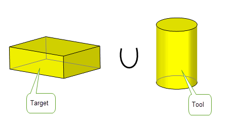
Figure 51-3 Bodies used in a simple union
For global booleans, all the boundary regions of the tool bodies lie either completely inside or completely outside of the target body, as shown in Figure 51-4.
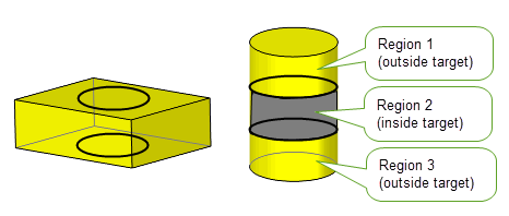
Figure 51-4 Boundary regions for global booleans
For local booleans, because not all faces of both bodies are used to compute the imprinted edges, boundary regions of the tool body are classified as inside if they are locally inside the target body near a loop of imprinted edges, and are classified as outside if they are locally outside near the loop of imprinted edges, as shown in Figure 51-5. Options are provided for you to select which regions are to be excluded or included in a local boolean: see Section 51.4.2, “Selecting regions in local booleans”.
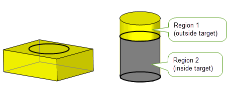
Figure 51-5 Boundary regions for local booleans
You can modify the behaviour of PK_BODY_boolean_2 (global booleans) and PK_FACE_boolean_2 (local booleans) using an options structure passed to each function. The options structures for these functions are different, but have a large number of identical options.The following table lists the options in these functions and indicates which ones can be used for global, local, manifold or general booleans:
The following table provides a summary of the options found in PK_BODY_boolean_2 and PK_FACE_boolean_2.
function |
The boolean operation to be performed: union, subtraction or intersection. Default: PK_boolean_unite_c |
configuration |
A sub-structure that describes the configuration of the target and tool bodies. See Section 51.4.1, “Optimising local and global boolean operations” for more information. |
default_tol |
The default tolerance to which the boolean operation, if it has to, may approximate entities or assume that entities are coincident. When performing global booleans with wire bodies, this option has no effect. Instead, set a tolerance on the vertices, using PK_VERTEX_set_precision. |
max_tol |
The maximum tolerance which may be applied to any entity involved in the boolean operation. |
matched_region |
A sub-structure that describes how matching between the target and tool bodies should be performed. See Section 51.4.5, “Matched topology in local and global boolean operations” for more information. |
selected_topolset |
A sub-structure for global booleans that is used to identify regions of the input bodies to be included in or excluded from the result body. See Section 51.4.3, “Selecting regions in global booleans”, for more information. |
select_region |
A sub-structure for local booleans that is used to identify regions of the input bodies to be included in or excluded from the result body. See Section 51.4.2, “Selecting regions in local booleans”, for more information. |
target_material_side |
Force the target to be treated as a solid or a sheet, or allow it to be treated according to its actual body type. Default: PK_boolean_material_default_c. See Section 51.4.14, “Specifying the body type of tool and target”, for details. Not supported for general booleans. See Section 53.6, “Unsupported options”. |
tool_material_side |
Force the tool to be treated as a solid or a sheet, or allow it to be treated according to its actual body type. Default: PK_boolean_material_default_c See Section 51.4.14, “Specifying the body type of tool and target”, for details. Not supported for general booleans. See Section 53.6, “Unsupported options”. |
imprint_complete_targ |
Turn imprint completion on and off for the target. Default: PK_imprint_complete_no_c See Section 51.4.13, “Imprint completion”, for details. |
imprint_complete_tool |
Turn imprint completion on and off for the tool. Default: PK_imprint_complete_no_c See Section 51.4.13, “Imprint completion”, for details. |
target_face_overflow |
How to process the overflow from a target body onto a tool body at the laminar edge of the target body. To use this option, See Section 51.4.6, “Overflow imprints at boundaries” for more information. |
tool_face_overflow |
How to process the overflow from a tool body onto a target body at the laminar edge of the tool body.To use this option, See Section 51.4.6, “Overflow imprints at boundaries” for more information. |
extend_face_list |
A local boolean receives a subset of the faces of a target and/or tool body. If the imprinting phase of the boolean results in incomplete loops of imprinted edges, this option specifies whether to use additional target and/or tool faces in an attempt to complete the loop. Default: PK_imprint_face_list_no_c. See Section 51.4.9, “Extending face lists during local booleans” for more information. |
limit_target_faces |
Limits the faces on the target body to be deleted. See Section 51.4.14, “Specifying the body type of tool and target” for more information. |
limit_tool_faces |
Limits the faces on the tool body to be deleted. See Section 51.4.14, “Specifying the body type of tool and target” for more information. |
imprint_overlapping |
Whether to imprint the boundaries of overlapping areas.See Section 51.4.7, “Imprinting the boundaries of overlapping areas” for more information. |
merge_imprinted |
Whether all mergeable imprinted edges on the result body that were imprinted by the boolean operation are merged. See Section 51.4.13, “Imprint completion” for more information. |
selective_merge |
Modify the edge merging behaviour. The merge phase avoids merging edges in the imprint that existed and were mergeable before the start of the boolean.This option should be used in conjunction with See Section 51.4.13, “Imprint completion” for more information. |
keep_target_edges |
Specify the edge that survives when a target edge and tool edge coincide during a boolean operation. This can be one of:
If both faces adjacent to the tool edge survive, then the tool edge survives, regardless of the value of this option. If generalised topology is on, the target edge always survives. |
merge_attributes |
Whether face attributes are merged during the boolean operations. See the PK Reference documentation for more information. Note: This option only takes effect when general topology is disabled. Attributes on coincident faces are always merged when general topology is enabled. (General topology is disabled by default when you start your Parasolid session.) |
merge_in_solid merge_in_solid_dimension |
See Section 53.3, “Merging redundant topology” for more information.
Default: PK_TOPOL_dimension_any_c See Section 53.3, “Merging redundant topology” for more information. Note: These options are only allowed when general topology is enabled. |
merge_in_face merge_in_face_dimension |
See Section 53.3, “Merging redundant topology” for more information.
Default: PK_TOPOL_dimension_any_c See the PK Reference documentation for more information. Note: These options are only allowed when general topology is enabled |
merge_in_edge |
Whether to merge out redundant vertices between edges in the result body which were not redundant in the tool or target bodies. See the PK Reference documentation for more information. Note: This option is only allowed when general topology is enabled. |
impose_bodies |
Controls whether the target body can impose on the tool bodies or vice versa. Default: PK_boolean_impose_no_c. See Section 53.3.1, “Finer control over region survival and inheritance” for more information. Note: This option is only allowed when general topology is enabled. |
merge_tools |
Whether to merge overlapping tools in a multi-tool boolean. Default: PK_merge_tools_no_c. See Section 53.3.1, “Finer control over region survival and inheritance” for more information. Note: This option is only allowed when general topology is enabled. |
prune_in_void |
Whether to prune all void regions in the resulting body. Any faces, edges or vertices in the result body which are completely surrounded by void regions are deleted, so long as the result body contains some pieces of a higher dimension, e.g. a sheet face is only deleted if the result body contains at least one solid region. See the PK Reference documentation for more information. Note: This option is only allowed when general topology is enabled. |
nm_edge_repair |
Whether to attempt to repair certain configurations of non-manifold results. Default: PK_nm_edge_repair_no_c. See Section 51.4.18, “Repairing non-manifold results using blends”. Not supported for general booleans. See Section 53.6, “Unsupported options”. |
blend_radius |
The radius to use for the new blends constructed to repair non-manifold edges when using the Not supported for general booleans. See Section 53.6, “Unsupported options”. |
stop_self_intersection |
Whether to stop self-intersection of tool faces which survive the boolean. After imprinting, tool faces which survive the boolean are compared against all surviving faces of the target body. |
resulting_body_type |
Specify the type of body that is returned by global and local boolean operations. Default: PK_boolean_prefer_original_c. See Section 51.4.17, “Specifying the body type of the result”, for details. |
allow_disjoint |
Whether to return a single disjoint body if the operation would result in more than one body. |
tracking |
Whether to request additional tracking data on the boolean result. |
tracking_type |
Allows you to specify the level of information you want the tracking records for the boolean operation to contain. Default: PK_boolean_track_type_basic_c. See Section 51.4.15, “Tracking imprinted edges” for more information. |
|
Allows you to track regions when performing boolean operations. See Section 51.4.16, “Tracking regions” for more information. Default: PK_region_track_no_c Not supported for manifold booleans. See Section 52.1, “Introduction”. |
flag_no_effect |
Determine whether the original target body was unaffected by the tools. Default: PK_boolean_no_effect_basic_c. |
check_fa |
Whether to check faces involved in the boolean operation. Only faces which are adjacent to imprinted edges are checked. Default: PK_boolean_check_fa_yes_c. |
fence |
Modify the behaviour of the subtract operation and determine which resultant bodies are returned when performing solid/ sheet (trimming) or sheet/solid (punching) boolean operations. It is recommended that you use Default: PK_boolean_fence_none_c. See Section 51.4.14, “Specifying the body type of tool and target”, for details. Not supported for general booleans. See Section 53.6, “Unsupported options”. |
update |
Update switch to maintain consistency when rebuilding models built in older versions of Parasolid. Default: PK_boolean_update_default_c. See Section 51.4.19, “Update control”, for more information. |
If the boolean operation involves instancing, i.e. a boolean operation which takes a single target body and a list of tool bodies, e.g. when drilling an array of holes in a body, the performance of the operation can be improved by using one of the following instancing options in the
configuration
option sub-structure:
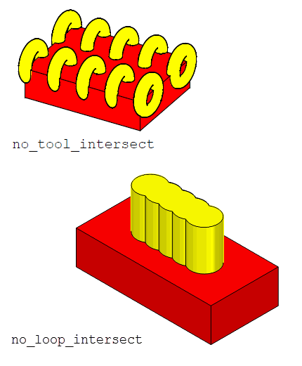
Figure 51-6 Situations in which instancing can be optimised during boolean operations
For a more efficient method of instancing when only a single tool body and a single target body are involved use PK_FACE_boolean_2 or PK_FACE_instance_bodies. PK_FACE_instance_bodies can also be used when you are using multiple tools.
These options are not supported for general booleans. See Section 53.6, “Unsupported options”.
|
Note: In this section, the term “region” refers to a boundary region as described in Section 51.3.5, “Boundary regions”, rather than a topological region as described in Chapter 14, “Model Structure”. A boundary region is a face set which lies wholly inside or outside the target or tool body. Tool faces which intersect the target body are split by the local boolean, and vice versa: the resultant faces lie wholly inside or outside the target body, or tool body, respectively. |
As described in Section 51.3.5, “Boundary regions”, boundary regions in the context of global booleans are always completely specified: regions that are included or excluded in the resulting body are always unambiguously defined. In local booleans, however, it can be unclear as to which regions should be included in the resulting body, and which should be excluded.
To address this problem, Parasolid lets you identify boundary regions in either the target or tool body that are to be included in or excluded from the result of a local boolean. You can do this using the
select_region
structure of PK_FACE_boolean_o_t.
The
select_region
structure identifies either all the regions in the result that you want to keep, all the regions you want to throw away, or a combination of both. Each region is identified by a single face, edge or vertex which is interior to it.
For an example of this functionality, see the code example in the
C++\Code Examples\Modelling\Booleans\Boolean
with
Selectors
folder, located in
example_applications
in your Parasolid installation folder.
Note: The
select_region
structure is ignored by PK_FACE_instance_tools in cases where there is more than one instance, unless all
configuration
options are true. See Section 54.2.2, “Improving the performance of instancing operations”, for more information. |
The structure contains the following fields:
Figure 51-7 illustrates the effect of defining regions to exclude during a local boolean. Two regions have been defined for the tool body, by specifying face 1 and face 2 in the
selectors
array. The
select_type
field is set to PK_boolean_exclude_c to ensure that these regions are excluded from the result. No help points are required, because both face 1 and face 2 lie completely inside a region created by combining the target and tool, ensuring that the regions to exclude are defined unambiguously
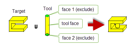
Figure 51-7 Excluding regions in a local boolean
Figure 51-8 illustrates the effect of defining regions to include. Here, face 1 from the tool is passed to the
selectors
array to define a single boundary region, and
select_type
is set to PK_boolean_include_c. Any other boundary regions in the tool are excluded from the resulting body.

Figure 51-8 Including regions in a local boolean
Figure 51-9 illustrates the effect of specifying help points to unambiguously define a region. A region has been defined for the tool body, by specifying face 1 (which is also the face used for the boolean operation itself) in the
selectors
array. The
select_type
field is set to PK_boolean_include_c to ensure that the region is included in the result.
Specifying this region without help points causes the boolean to fail, because face 1 lies in several of the regions that are created by combining the target with the tool (in fact, it lies in all the possible regions). The boolean can be made to succeed by specifying a help point which lies in the region that you want to include.
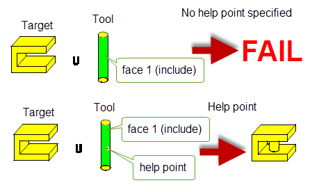
Figure 51-9 Using help points to identify regions in a local boolean
Using the
selected_topolset
option, you can alter the result of a boolean operation by choosing to keep or discard topolsets in the target or tool body that would otherwise have been excluded or included in the operation. Topolsets are connected sets of solid regions and boundary regions which are bounded by the imprint (of the boolean operation) and are chosen by specifying a selector topology that lies within that topolset. Selector topologies can be solid regions, faces, edges or vertices. The
selected_topolset
option structure contains the following options:
You can set
target_select
and
tool_select
to any of the following values:
Selected topolsets from either the target or tool body have to be all excluded or all included. You cannot exclude some topolsets from a body and include others. from the same body.The exclusion or inclusion of a selected topolset holds for the duration of the chosen boolean operation. All other non-selected topolsets from the same origin are either included or excluded respectively.
Note: Multiple tools can be used with the
selected_topolset
option. |
The topolsets that can be chosen depend on the boolean operation being performed. For unite operations,
selectors
determines whether a topolset from either the target or tool will survive after the operation.
Figure 51-10 shows a unite boolean between a solid target and solid tool. The face surrounded by a blue frame on the tool body is the selected topology and
tool_select
is set to PK_selector_type_exclude_c.
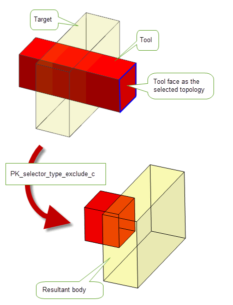
Figure 51-10 Unite boolean with
selected_topolset
on the tool body
Figure 51-11 shows the same unite boolean between a solid target and solid tool. In this case, an edge of the tool body is the selected topology and
tool_select
is set to PK_selector_type_include_c.
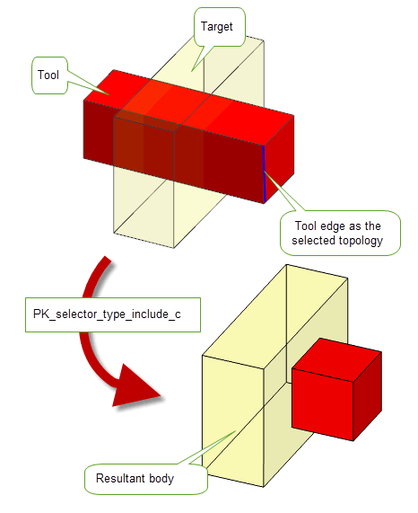
Figure 51-11 Unite boolean operation with
selected_topolset
on the tool body
In cases where the boolean operation splits the selected topolset, you can either choose to propagate the selection to all topolsets on the same body using the
split_action
option or you can provide
help_points
to show which of the topologies resulting from the split are being specified.
The
help_points
must each uniquely identify a topolset and must lie within their corresponding selector topology.
Figure 51-12 illustrates the use of
help_points
in a unite boolean between a solid tool and a solid target. The tool has one help point in a topolset and the
tool_select
is set to PK_selector_type_exclude_c.
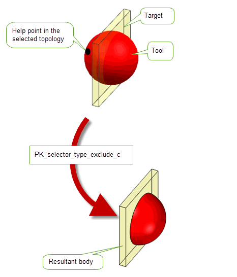
Figure 51-12 Unite boolean using
help_points
If you choose not to supply help points, the
split_action
option can be used which takes the following values:
|
Propagate the selection to all the topological entities derived from the selector after the split. |
Figure 51-13 shows a unite boolean with a solid tool and target. No help points have been set, the selector is from one topolset on the tool body and
split_action
has been set to PK_selector_split_propagate_c. The selector type has been set to PK_selector_type_exclude_c.
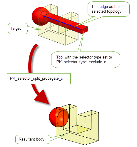
Figure 51-13 Unite boolean using
split_action
Note: If
help_points
are set for the selector, then the value of
split_action
is ignored. |
The
selected_topolset
option can be used with
target_material_side
and
tool_material_side
options (referred to hereafter as the material-side options). The selector is first located on the model and then the chosen material-side option is taken into account. If the selector topology is found to be invalid due to the material-side options then an error is returned. If the selector topology remains valid, the boolean operation is then performed taking the material-side options into account.
Figure 51-14 illustrates a unite operation with a solid tool and solid target. One face on the tool has a help point and is set to exclude the mid-face. The material-side options for the tool body are set to the default and the material-side option for the target body is set to target_material_outside.
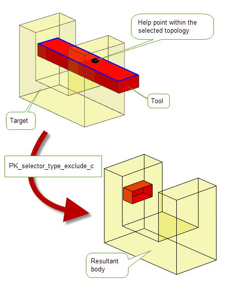
Figure 51-14 Unite boolean with material-side options on the target body
Figure 51-15 illustrates a unite operation between a solid target and solid tool. Both bodies have their respective material-side options set to
material_outside
and a help point is set on the tool body.
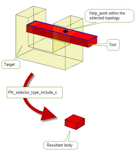
Figure 51-15 Unite boolean with material-side options set on both the target and tool
Note: When using this option, the
fence
option should be left at its default value of PK_boolean_fence_none_c. Material-side options can be used to produce the desired fencing result. See Section 51.4.14, “Specifying the body type of tool and target”, for more information on material-side options. |
When performing global and local boolean operations, Parasolid can automatically look for regions between the target and tool that are nearly coincident. These regions, known as matched regions, represent areas of overlap between two topological entities that are geometrically coincident to within a specified tolerance. Using matched regions can produce a better result (by ensuring the coincident regions match as closely as possible) and can also make the boolean operation faster.
In general, we recommend that you let Parasolid control how matched regions are identified, by following the recommendations in the note below. However, if your application already has information about matched regions, then you can optionally supply these to provide further aid to the boolean operation.
Matched region information is controlled using the
matched_region
structure (PK_boolean_match_o_t) in PK_BODY_boolean_o_t, PK_FACE_boolean_o_t, PK_BODY_imprint_faces_o_t, PK_BODY_imprint_o_t, PK_FACE_imprint_faces_o_t, PK_FACE_imprint_o_t, PK_BODY_section_o_t and PK_FACE_section_o_t.
Note: To get the best results from matched regions, we strongly recommend that you set
match_style
to PK_boolean_match_style_auto_c and, optionally, set a tolerance using
auto_match
and
auto_match_tol
. If you want to supply your own matched region information, read the rest of this section. |
The
matched_region
structure takes the following information:
match_style |
Controls how Parasolid automatically looks for matched regions. This can have the following values:
We recommend that you always use PK_boolean_match_style_auto_c to switch on auto-matching of topologies during these operations. See Figure 51-18 for an example. |
auto_match |
When
For boolean and sectioning operations, this field can be set to PK_LOGICAL_true if
For imprinting operations, this field must be set to PK_LOGICAL_true if
match_style
is PK_boolean_match_style_auto_c. |
auto_match_tol |
An optional tolerance value to use when automatically selecting matched regions. Note: This field should only be used if
match_style
is PK_boolean_match_style_auto_c and
auto_match
is PK_LOGICAL_true. |
n_match_regions match_regions |
The
If your application already has information about suitable matched regions, it can supply them using
If
match_regions
if your application already has this information available. |
update |
If your application relies on reproducing behaviour when updating models created using old versions of Parasolid, you should use this option to preserve old behaviour and help eliminate differences in rebuild results. You can use it to disable enhancements to boolean matching that have been added at different Parasolid versions. Doing this ensures that matching gives the same results in the latest version of Parasolid as in older versions. See PK_boolean_match_update_0_c in the PK Interface Programming Reference Manual, for more information on this update option. |
If your application already has the information, then you can supply pairs of matched entities in the
match_regions
substructure, using the following information:
|
A pair of topological entities that are to be treated as matched. The following combinations of entities can be matched: |
|
|
The type of match. See below for details. (Default: PK_boolean_match_exact_c) |
|
|
The tolerance within which the matched entities are geometrically coincident. |
The
match_type
classifies the relationship between the entities:
The following table shows the relationship between
regions
and
match_type
:
When supplying matched regions of type face-face or face-edge, it is recommended that you always use
match_type
overlap.
In Figure 51-16 the tool body is a copy of the target body reflected about the plane of face F1.
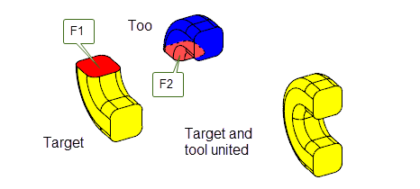
Figure 51-16 Unite boolean with matched faces
Uniting the two bodies may fail due to the near coincident and tangential geometry meeting at the boundary of face F1 and F2. This is especially true if the geometry is of an approximate nature.
Specifying face F1 and F2 as a matched pair, with a suitable tolerance, enables the unite operation to succeed. The
match_type
should be overlap.
In Figure 51-17 the target and tool bodies have been created by sweeping different profiles along the same guide path.
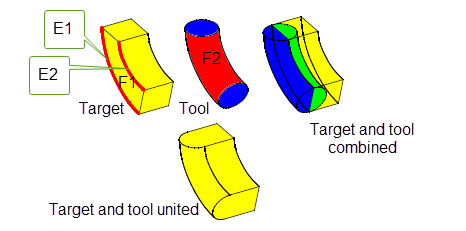
Figure 51-17 Unite boolean with matched face and edges
Boolean operations have difficulty with such bodies due to the approximate nature of the geometry of face F1 and F2. The boundaries of face F1 lie within a tolerance of face F2.
Specifying the face, F2, and the edges, E1 and E2, as matched topology, with a suitable tolerance, enables the unite operation to succeed. The
match_type
should be overlap.
In Figure 51-18, the target and tool bodies can be united at the base.
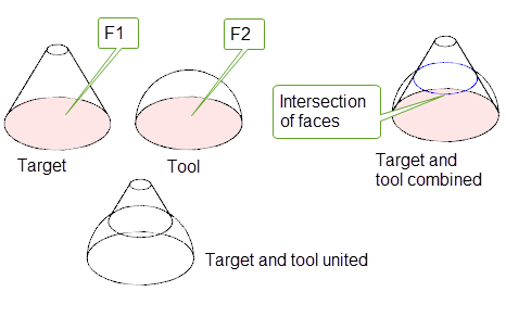
Figure 51-18 Unite boolean with intersecting neighboring faces
Specifying the base of the cone F1, and the base of the hemisphere, F2, as matched topology, with a suitable tolerance, lets the unite operation succeed if
match_style
is set to PK_boolean_match_style_auto_c. Because the neighbouring faces of the matched topology intersect in the united body, using the default
match_style
of PK_boolean_match_style_basic_c would cause the unite operation to fail.
In addition to tangential imprint completion, you can also complete imprints at laminar boundaries using ruled and swept solutions, allowing you to preserve the laminar boundary in the region of the trim. Depending on the operation you want to perform, there will be some cases where the tangential solution gives the ideal result, and other cases when ruled or swept solutions are more appropriate.
Figure 51-19 shows how imprint completion on a flat sheet target causes the imprinted edges to overflow onto the V-shaped tool body that created the imprints. The result that is created by completing the imprint tangentially is generally not the result that you are likely to want. Instead, you can opt to create an alternative solution by using the options described below.
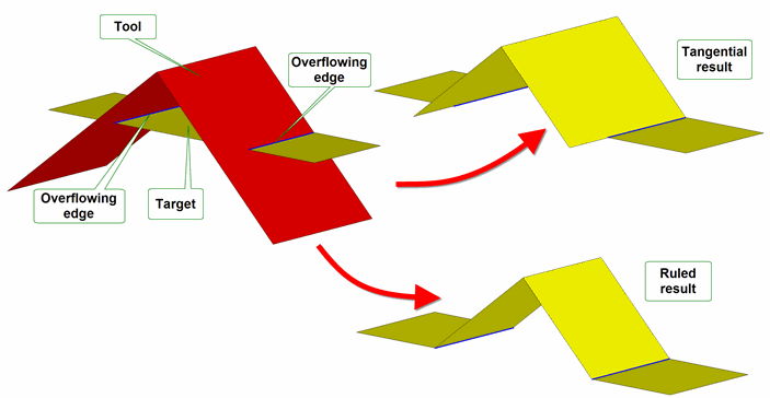
Figure 51-19 How imprints on a target can overflow onto the tool
You can control Parasolid’s behaviour for overflows such as this using the
target_face_overflow
and
tool_face_overflow
options; the option you need to use depends on whether you are completing imprints on the target or the tool.
These options are not supported for general booleans. See Section 53.6, “Unsupported options”.
Both of these options structures themselves contain the following options for specifying how to handle imprint overflow:
Figure 51-20 shows the non-tangential results that can be obtained by specifying different
laminar_overflow
behaviour for a given tool, where imprint completion is taking place on the tool.
In each case, the following options have been set:
function
is PK_boolean_unite_c.
target_material_side
and
tool_material_side
are both set to PK_boolean_material_inside_c.
target_face_overflow
has been used.The results for each type of overflow have been obtained as follows:
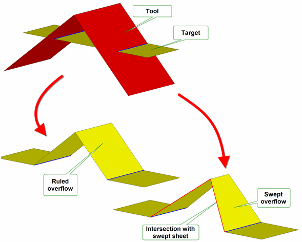
Figure 51-20 Different methods for overflowing imprints at laminar boundaries
Figure 51-21 shows the effect of setting the
laminar_walled
option to PK_LOGICAL_true. In this example, to create a result body on which a side face can be built, the following options have been set:
function
is PK_boolean_unite_c.
laminar_overflow
is set to PK_FACE_overflow_ruled_c.
target_material_side
is PK_boolean_material_inside_c and
tool_material_side
is PK_boolean_material_inside_c.
target_face_overflow
has been used.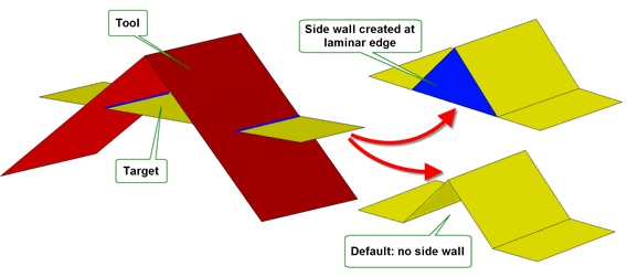
Figure 51-21 Creating a side face for overflowing imprints at laminar boundaries
|
Note: There are restrictions on how you can combine the use of imprint completion and overflow behaviour, as follows: |
As well as providing control over overflowing imprints at laminar boundaries, Parasolid lets you specify how overflowing imprints at interior boundaries should be processed. The interfaces you use to control these overflows are similar to the ones used to control overflowing imprints at laminar edges (described in Section 51.4.6.1, “Dealing with overflowing imprints at laminar boundaries”), though the behaviour provided is different.
As with overflows at laminar boundaries, you control overflows at interior boundaries using the
target_face_overflow
and
tool_face_overflow
options; the option you need to use depends on whether you are completing imprints on the target or the tool.
Unlike overflows at laminar boundaries, interior overflows are only feasible for local booleans, and should therefore only be specified in calls to PK_FACE_boolean_2.
Both of these options structures themselves contain the following option for specifying how to handle imprint overflow:
interior_overflow |
How to handle imprint overflow onto the tool (for
|
|
Note: When using PK_FACE_overflow_mixed_c, the settings for the material side options, and the boolean operation used, can both affect whether an edge is regarded as concave or convex. |
Figure 51-22 shows the results obtained by specifying different
interior_overflow
behaviour for a given tool and target, where imprint completion is taking place onto the tool.
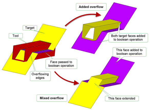
Figure 51-22 Different methods for overflowing imprints at interior boundaries
In each case, the following options are set to the same values as for the example in Section 51.4.6.1, “Dealing with overflowing imprints at laminar boundaries”:
function
is PK_boolean_unite_c.
target_material_side
and
tool_material_side
are both set to PK_boolean_material_inside_c.
target_face_overflow
has been used.The results for each type of overflow have been obtained as follows:
You can use the
imprint_overlapping
option in PK_BODY_boolean_o_t to imprint any boundaries in overlapping areas in cases where a face from the target and a face from the tool share the same surface. This is useful if you have scribed details onto a body that you want to preserve. By default, overlapping boundaries are not imprinted on the boolean result.
Figure 51-23 illustrates the behaviour of this option.
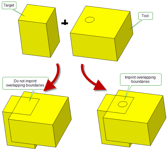
Figure 51-23 Imprinting overlapping boundaries
This option is not supported for general booleans. See Section 53.6, “Unsupported options”.
When performing local booleans using PK_FACE_boolean_2, you can use the
limit_target_faces
and
limit_tool_faces
options to limit the scope of the local boolean when trimming and joining sheet targets or tools.
When
limit_target_faces
is PK_LOGICAL_true, the boundaries of the
targets
passed to PK_FACE_boolean_2 are used in the imprint phase of the boolean to complete the imprints. Similarly, when
limit_tool_faces
is PK_LOGICAL_true, the boundaries of the
tools
are used in the same way.
This has the effect of ensuring that only the specified
targets
or
tools
(as appropriate) are considered as candidates for trimming: any faces from the owning body that are not explicitly passed to PK_FACE_boolean_2 as either
targets
or
tools
will not be trimmed. If either
limit_target_faces
or
limit_tool_faces
is PK_LOGICAL_false - the default setting - any faces in the owning body may be trimmed, even if they have not been specified as
targets
or
tools
.
The effects of using
limit_target_faces
are illustrated in
Figure 51-24, which shows how you can trim just the side faces of a boss in a sheet body by specifying only those side faces and setting
limit_target_faces
to PK_LOGICAL_true.
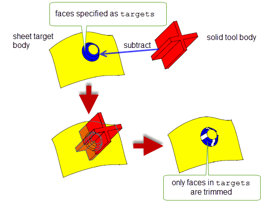
Figure 51-24 Limiting trim faces to those specified as targets
Figure 51-25 shows a more detailed view of the boss before and after the boolean operation shown in Figure 51-24 has been performed.
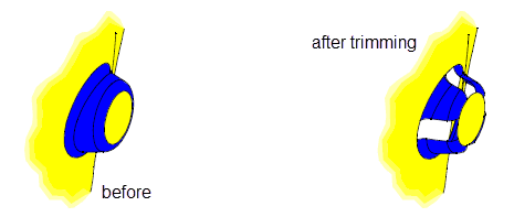
Figure 51-25 Trimming the side faces of a boss
The
limit_target_faces
and
limit_tool_faces
options can only be used if both the following are true:
target_material_side
option set to PK_boolean_material_none_c (see Section 51.4.14).
extend_face_list
must be PK_imprint_face_list_both_c (see Section 51.4.9, “Extending face lists during local booleans”). 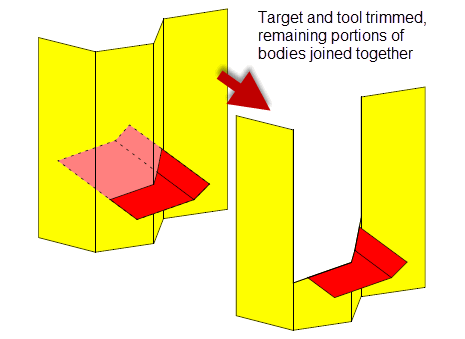
Figure 51-26 Boolean join operation
During the imprint phase of a local boolean, you can use the
extend_face_list
option of PK_FACE_boolean_2 to add adjacent faces to the tool or target (or both) in an attempt to prevent incomplete loops of edges. This option is identical to the
extend_face_list
option available for PK_FACE_imprint_faces_2: see Section 50.4.1, “Imprinting”, for more details.
Figure 51-27 illustrates the punching of a target sheet body with solid tool bodies, so that the areas of the target outside the tools, plus the areas of faces of the tools on one side of the target are the resultant sheet body.
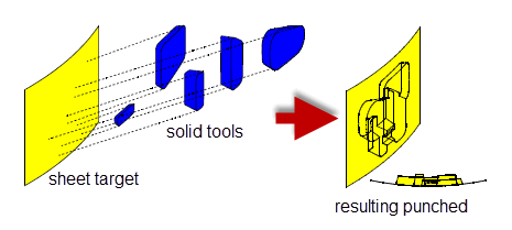
Figure 51-27 Punching a target (sheet) body with 5 solid tool bodies
Note: More generalised punching functionality is supported via the
target_material_side
and
tool_material_side
options. See Section 51.4.14, “Specifying the body type of tool and target”, for details. |
It is possible to enclose solid regions or add solid regions to an existing solid body by uniting the solid body with a sheet body as shown in Figure 51-28. The sheet body must enclose a valid manifold solid region within the solid body. This operation is only valid with generalised topology disabled.
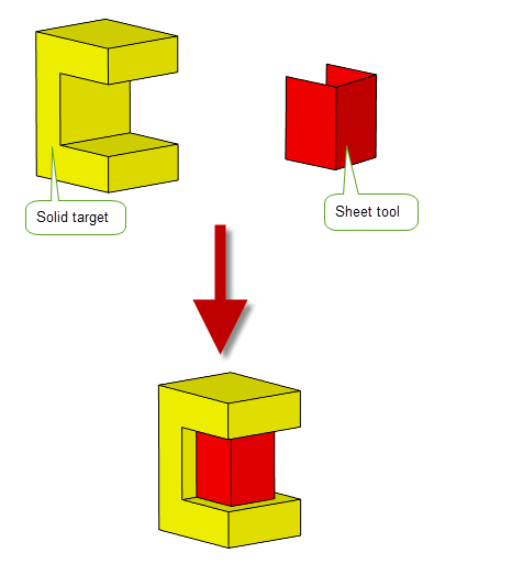
Figure 51-28 Uniting solid and sheet bodies to enclose a solid region
Note: Enclosure functionality is also supported via the
target_material_side
and
tool_material_side
options. See Section 51.4.14, “Specifying the body type of tool and target”, for details. |
Use of the
fence
option controls which regions of the sheet body are returned.
Subtracting sheet body from solid body using the ‘none’ fence option
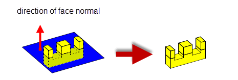
Figure 51-29 Solid sectioned by sheet, 4 bodies returned.
Subtracting sheet body from solid body using the ‘front’ fence option

Figure 51-30 Solid sectioned by sheet - only regions in front of the sheet body are returned, 3 bodies returned.
Subtracting sheet body from solid body using the ‘back’ fence option
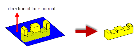
Figure 51-31 Solid sectioned by sheet - only regions behind the sheet body are returned, 1 body returned.
This option is not supported for general booleans. See Section 53.6, “Unsupported options”.
Note: Fencing functionality is also supported via the
target_material_side
and
tool_material_side
options. We strongly recommend that you use these options when performing fencing operations. See Section 51.4.14, “Specifying the body type of tool and target”, for details. |
During the imprinting phase of both local and global sheet booleans, you can request that Parasolid extends any imprinted edges tangentially. When used in conjunction with the material side options (see Section 51.4.14, “Specifying the body type of tool and target”), this makes it easy, for example, to split a sheet target using a sheet tool, without having to ensure that the tool is large enough to perform the operation successfully, as shown in Figure 51-32.
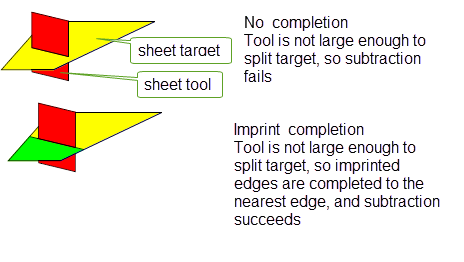
Figure 51-32 Splitting large sheet targets using imprint completion
As well as completing imprints on a sheet target, you can also complete imprints on a sheet tool if you wish. You use the
imprint_complete_targ
and
imprint_complete_tool
options in PK_BODY_boolean_o_t and PK_FACE_boolean_o_t to switch on imprint completion in the target or tool respectively.
You can only complete imprints on the target from the laminar edges of the supplied tool (and vice versa when completing imprints on the tool). Thus, if the tool contains non-laminar edges that intersect the target, you cannot extend their imprinted edges from the point of intersection, as illustrated in Figure 51-33.
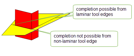
Figure 51-33 Splitting large sheet targets using imprint completion
This functionality is very similar to Parasolid’s support for completing imprints created by PK_BODY_imprint_body and PK_FACE_imprint_faces_2. This is described in Section 50.5, “Legacy curve imprinting”, and you should look there for more details on how the boolean imprint completion functionality works.
The only difference between the two types of imprint completion is that imprints created using boolean functions can only be completed tangentially, whereas imprints created using imprint functions can be completed tangentially or orthogonally.
You can use the
tool_material_side
and
target_material_side
options to control how the tools and targets specified in boolean operations are interpreted with regard to their body type. This section:
The material-side options let you treat faces locally as if they come from a body of a different type. Faces on a sheet body can be treated as if they are part of a solid and faces from a solid body can be treated as if they are part of a sheet. Use
tool_material_side
to control faces in tools and
target_material_side
to control faces in targets.
For each of these material-side options the following settings are available:
For an example of this functionality, see the code example in the
C++\Code Examples\Modelling\Booleans\Boolean
Material
Side
folder,
C#\ExampleApplication.Net\Code
Examples\Modelling\Booleans\Boolean Material Side
located in
example_applications
in your Parasolid installation folder.
These options are not supported for general booleans. See Section 53.6, “Unsupported options”.
Simple usage of material-side options with boolean operations are illustrated in this section. Each image uses the same model with different combinations of material-side options applied. The model is divided into four numbered imaginary volumes, each representing a possible region in the result. Figure 51-34 explains what region of the model each volume represents. Each volume will be either treated as solid or void depending on the material-side options.
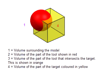
Figure 51-34 The regions that the volumes of the model represent
|
Note: For some combinations of options, volume 1 should be solid after the boolean has been completed. Since this is clearly invalid, Parasolid negates all solid and void volumes (including volume 1) in these cases so as to ensure a valid result.Volumes that would have been treated as void in the end result prior to the flip are shown with their numbers crosses out in red. See Section 51.4.14.9, “Summary” for more information. |
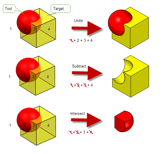
Figure 51-35 Boolean operations with material-side options set to PK_boolean_material_inside_c for both the target and the tool (default settings)
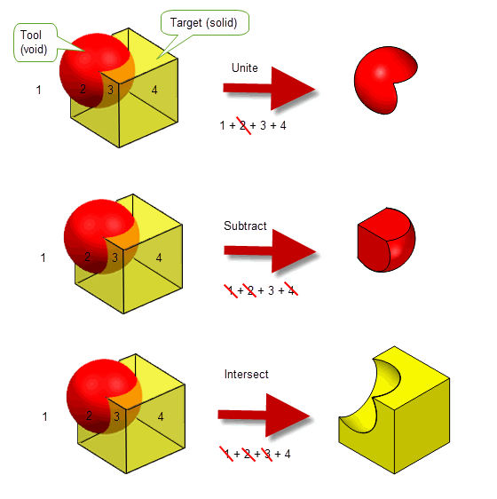
Figure 51-36 Boolean operations with material-side options set to PK_boolean_material_inside_c for the target and PK_boolean_material_outside_c for the tool.
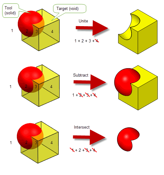
Figure 51-37 Boolean operations with material-side options set to PK_boolean_outside_c for the target and PK_boolean_inside_c for the tool.
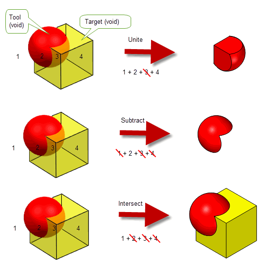
Figure 51-38 Boolean operations with material-side options set to PK_boolean_outside_c for both the target and the tool.
Material-side options can be used with boolean operations to achieve a number of different results. See Section 51.4.14.3, “Achieving different effects with material-side options”
Depending on the configuration of the tool and target bodies, the boolean operation being performed, and the values chosen for the material-side options, a variety of different effects can be achieved. In particular, you can use these options to:
This section describes each use in turn.
You can create a simple corner by performing a boolean between two sheets and setting the material-side option for both the target and the tool to PK_boolean_material_inside_c. The boolean operation you perform, and the value of the material-side option chosen, determines the configuration of the resulting sheet body corner, as shown in Figure 51-39. Parasolid ensures that the normals on the resulting faces are consistent, preserving the normal on the target body in the process.
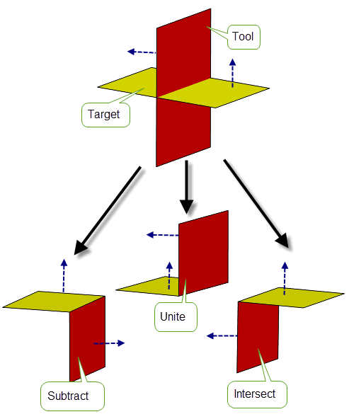
Figure 51-39 Creating simple corners using different boolean operations
|
Note: If you wish, you can use PK_boolean_material_outside_c to create corners in this way as well. |
You can also use the imprint completion functionality described in Section 51.4.13 to create more complex corner configurations in cases where one body does not intersect the other body completely, as shown in Figure 51-40. When imprint completion is turned off, Parasolid would return a failure for a boolean such as this, regardless of the material-side option settings.
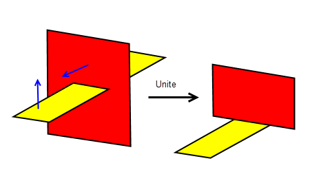
Figure 51-40 Using imprint completion to create more complex corners
You can use material-side options to punch a solid tool into a sheet target, for example by setting
target_material_side
to PK_boolean_material_inside_c and performing either a subtract or a unite operation to produce a sheet body. The final shape of the punched target depends on the direction of the face normal of the target, and which operation is performed, as shown in
Figure 51-41.
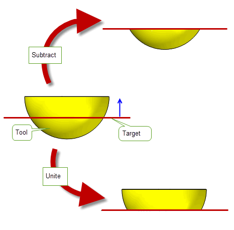
Figure 51-41 Punching a solid tool into a sheet target
In addition, you can punch a sheet tool into a sheet target by setting the material-side options of both target and tool to PK_boolean_material_inside_c. Punching sheets in this way requires the same operation and settings as creating corners, and is actually just a more general version of the same technique.
To represent fence information when performing a boolean between a sheet tool and a solid target, set
tool_material_side
and perform a subtract operation to produce a solid body. The direction of the fencing operation (that is, which part of the target remains), depends on the value of
tool_material_side
, as follows:
|
PK_boolean_material_none_c. This is the default. |
Figure 51-42 shows how you can emulate “front” fence and “back” fence behaviour (as described in Section 51.4.12) using this technique:
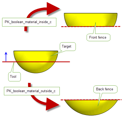
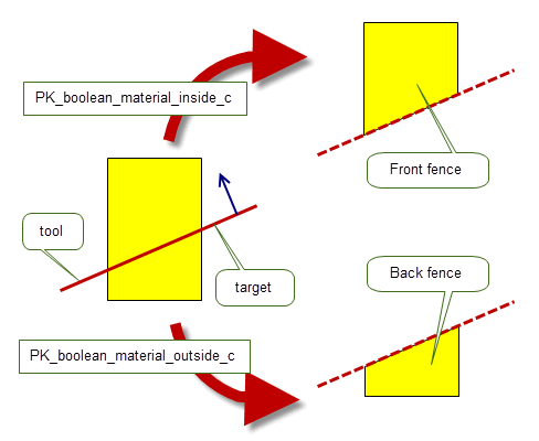
Figure 51-42 Performing fence operations using material-side options
|
Note: It is possible to perform fencing operations using a number of different combinations of material-side option values and boolean operations. The setting described here are the recommended ones. |
You can also use the material-side options to enclose a solid region with a sheet body (as described in Section 51.4.11) by uniting a solid target and a sheet tool, and setting
tool_material_side
to PK_boolean_material_inside_c.
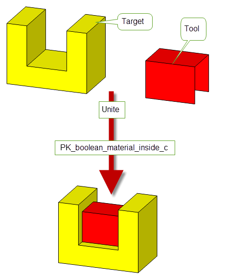
Figure 51-43 Enclosing a solid region with a sheet
|
Note: Enclosure, as described in Section 51.4.11, is the default behaviour when uniting a solid target and sheet tool using the default values for all boolean options. However, if you want to implement enclosure functionality using the material-side options, you should use the settings described here. |
There are a few constraints when using material-side options. These are as follows:
tool_material_side
in PK_BODY_boolean_2 to a non-default value, there must be a single tool body.
tool_material_side
and
target_material_side
must be either PK_boolean_material_default_c or PK_boolean_material_none_c. No other values have any meaning.This section summarises the results of using the material-side options.
Both PK_BODY_boolean_2 and PK_FACE_boolean_2 let you track edges that are imprinted onto the target during a boolean operation, subject to the following restriction:
You can control the amount of tracking information that is returned using the
tracking_type
option, which can take the following values:
|
Return basic tracking information that associates imprinted edges with the target topology on which those edges are imprinted. This is the default. |
|
|
Return complete tracking information that associates imprinted edges with the following:
Figure 51-44 shows an example that illustrates the second of these. |
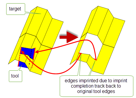
Figure 51-44 Tracking imprint completion back to originating tool topology
You can use the
track_regions
option to specify the level of region information to be tracked and recorded by PK_BODY_boolean_2. This tracking information is returned for both new regions and original regions that have been affected by a boolean operation.The
track_regions
option takes the following values:
|
No region tracking information is returned for boolean operations. |
|
|
Returns a set of basic region tracking records (PK_TOPOL_track_record_r_t) as follows:
tracking
option to PK_LOGICAL_true and have general topology enabled in the session. |
In Figure 51-45 the boolean unite result general body has three solid regions. Region (r1) is derived from the solid region of the target, region (r2) is derived from the solid regions of both the target and the tool and region (r3) is derived from the solid region of the tool.
The tracking of each of these regions is returned as a record of type PK_TOPOL_track_derive_c. For more information about Regions see Section 14.2.2, “Region”.
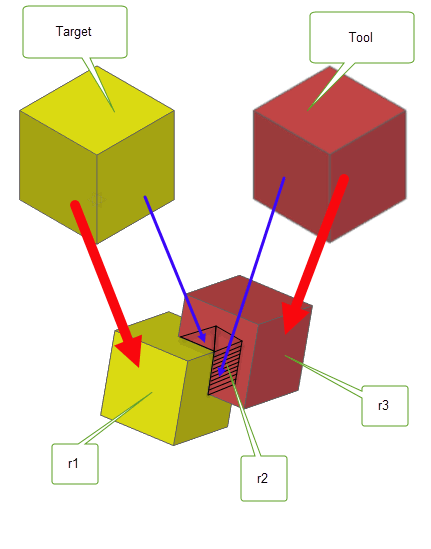
Figure 51-45 Tracking regions using the
track_regions
option.
You can specify the preferred type of the resulting body for both global and local booleans using the
resulting_body_type
option. This takes the following values:
|
Returns solid result bodies if all shells in the bodies are closed, otherwise returns sheet bodies.
|
|
|
Returns sheet bodies if possible.
If the result contains several components, they are returned as separate bodies if |
|
|
Returns manifold wire bodies. This value only applies to PK_BODY_boolean_2. |
|
|
Returns general bodies. This value only applies to PK_BODY_boolean_2. |
|
|
Ensures that the result bodies has the same body type as the target. If this is not possible, an error is returned. You should ensure you use this value if the |
|
|
Returns the simplest possible body type it can without making any changes to the body. This value only applies to PK_BODY_boolean_2. It is recommended to use this value instead of the default when generalised topology is enabled. |
Sometimes, boolean operations fail because the resulting bodies are non-manifold. When performing global booleans, Parasolid can automatically repair certain configurations of non-manifold edge by replacing that edge with blend faces, thereby allowing the boolean operation to succeed. You can control this behaviour using the following options:
nm_edge_repair |
Whether to attempt to repair non-manifold edges in the resulting body. Set this to PK_nm_edge_repair_blend_c if you want to attempt to repair non-manifold edges. Default: PK_nm_edge_repair_no_c |
blend_radius |
The radius of the blends that are created in order to repair a non-manifold edge. Default: 1.0e-5 |
These options are not supported for general booleans. See Section 53.6, “Unsupported options”.
Figure 51-46 shows an example where the non-manifold edge created by subtracting the cylinder from the cube has been successfully repaired by replacing it with two blends, thus allowing the boolean operation to succeed.
|
Note: This option is only intended to repair non-manifold edges created by booleans in which the target and tool share a common extrude direction (the vertical axis, in
Figure 51-46), thereby creating non-manifold edges that lie in this same direction. More general configurations creating non-manifold edges are not guaranteed to work. |
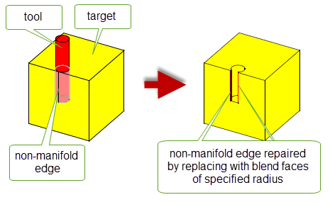
Figure 51-46 Repairing non-manifold edges in global booleans
If your application relies on reproducing behaviour when updating models built using earlier versions of Parasolid, you should use the
update
option to preserve old behaviour and help eliminate differences in the rebuild results.The option lets you disable some boolean enhancements that have been added at different Parasolid versions. Doing this ensures that boolean operations give the same results in the latest version of Parasolid as in older versions.
See PK_boolean_update_t in the
PK Interface Programming Reference Manual for more information on this
update
option.
|
Note: The default value is PK_boolean_update_default_c which uses all appropriate boolean operations enhancements. Setting to a non-default value disables all appropriate boolean operations enhancements. |
Note: The imprinting functions PK_BODY_imprint_body, PK_BODY_imprint_faces_2, and PK_FACE_imprint_faces_2 also use the
update
option. For these functions, update values PK_boolean_update_5_c and older give the same behaviour. See Section 50.4.1, “Imprinting”, for more information.Note: The sectioning functions PK_BODY_make_section and PK_BODY_make_section_with_surfs also use the
update
option. For these functions, update values PK_boolean_update_v261_c and older give the same behaviour. See Section 55.5, “Non-destructive sectioning”, for more information. |
In addition to returning tracking information, both PK_BODY_boolean_2 and PK_FACE_boolean_2 have a results structure containing the result bodies, a Parasolid report, and a status code. The status code is returned in the
result
field of the results structure and communicates information regarding the overall success or failure of the boolean operation as follows:
For further information on material-side options, see Section 51.4.14, “Specifying the body type of tool and target”.
See Section 120.3.1, “Types of failure status code returned”, for more information on status codes.
Figure 51-47 shows an example where a boolean operation is used to subtract a slot from a block. In this example, face ‘A’ is split creating the new face ‘B’ resulting in both the ‘A’ and ‘B’ faces sharing the original surface. Similarly this applies for edges ‘C’ and ‘D’ as they have a common direction.
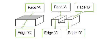
Figure 51-47 Two faces sharing the same surface
|
Note: If the example illustrated in
Figure 51-47 used facet geometry, then faces ‘A’ and ‘B’ would not share the surface but would have separate meshes. Similarly the edges ‘C’ and ‘D’ will have separate new plines. |
In Figure 51-48 face ‘E’ has the same surface as face ‘1’ and face ‘F’ has the same surface as face ‘2’. Therefore, if face ‘1’ and face ‘2’ shared the surface to begin with, then face ‘E’ and face ‘F’ share the surface in the result.
After the subtraction boolean faces ‘A’ and ‘B’ share the surface of the bottom of the tool, and faces ‘C’ and ‘D’ share the surface of the back of the tool since they were created from those surfaces of the tool.
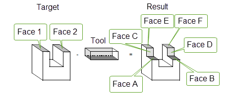
Figure 51-48 Subtracting a tool from a target
Figure 51-49 is similar to the previous example except that the target and tool are reversed. In this example the sharing of the surface under faces ‘A’ and ‘B’ is determined by the sharing of the surface under faces ‘1’ and ‘2’; if ‘1’ and ‘2’ share, then so do ‘A’ and ‘B’.
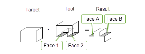
Figure 51-49 Subtracting a tool from a target
| <<< Imprinting and Curve Projection | Chapters | Manifold Booleans >>> |