
 |
Lattice Geometry |
| <<< Nominal Geometry | Chapters | Transformations >>> |
Lattices are classified as a geometry type which can be created, enquired of, rendered and attached to parts as construction geometry. Lattices can be used to create mesh geometry as well as solid convergent bodies. Furthermore, you can create a lattice structure from a smaller core lattice. Lattices can be rendered as straight lines, or as solid spheres linked by cylindrical or conical rods (as illustrated in Figure 20-1).
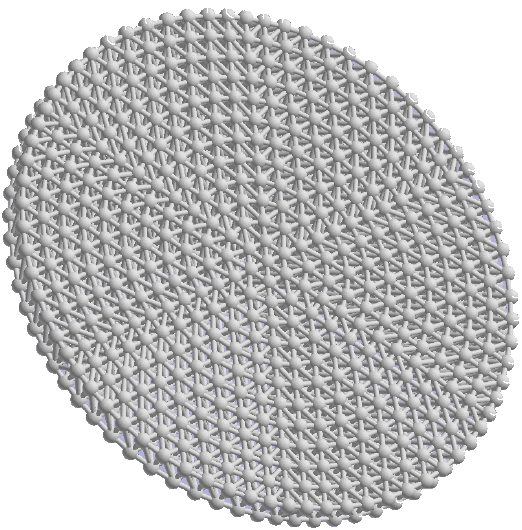
Lattices are represented as collections of lballs joined by lrods (collectively known as lattice topology or ltopols). The radii of lrods can be different where they meet at a common lball, as illustrated in Figure 20-2.
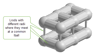
Figure 20-2 Lattice with lrods of different radii meeting at a common lball
Parasolid provides the function PK_LATTICE_create_by_graph to allow you to create an orphan lattice geometry from data supplied by a user-defined callback function.
The function receives the following arguments:
|
A user-defined callback function.See Section 20.2, “Using the graph reader”, for more information. |
|
The function has the following options:
|
Estimated number of all lballs returned by all calls to |
|
|
Estimated number of all lrods returned by all calls to |
|
|
Function to free data blocks returned by |
|
|
Whether the |
|
|
Controls behaviour when a supplied lball radius is smaller than the radius of its largest incident lrod. This can have the following values:
|
|
|
Whether the lattice is blended. Default: PK_LBALL_blend_none_c See Section 20.5, “Creating a blended lattice” for more information. |
|
|
The size of the lball blends in the lattice. Default: 0 See Section 20.5, “Creating a blended lattice” for more information. |
|
|
If
The |
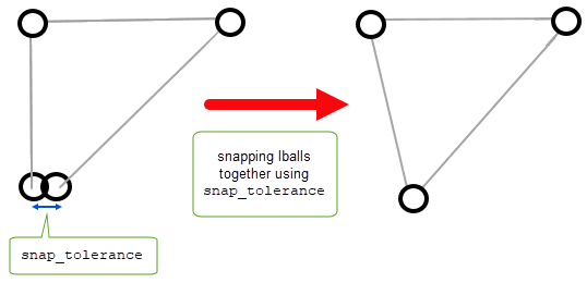
Figure 20-3 Snapping lballs together that lie within a supplied
snap_tolerance
This section describes how the callback function,
graph_reader
, is used to create lattice geometry from graph data. The
graph_reader
takes a block of user supplied context information and should return a block of lattice data and a return status. The block of lattice data can be one of two types; cylinder or cone. See Section 20.3, “Graph types” for more information.The return status indicates the state of the operation. The
graph_reader
is called repeatedly by PK_LATTICE_create_by_graph until it returns the status PK_LATTICE_cb_status_stop_c.
This section describes the two types of data blocks (cylinder and cone) that can be returned by each call to
graph_reader
.
This structure contains the data block for lattices with cylindrical shaped lrods. The lballs are provided by arrays of
lball_positions
and
lball_radii
. The
lrod_start_indices
and
lrod_end_indices
arrays define an array of lrods by specifying the absolute indices of the pair of lballs that each lrod joins.
Individual blend sizes of the lballs within the data block can be supplied via
lball_blend_sizes
. If the lattice is to be blended, these sizes together with the value of the
lball_blend_type
option determine the radii of the blends applied at each of the lballs. See Section 20.5.2, “Blended lattices with lballs of various blend sizes” for more information.
The following pseudo-code example shows the data input when using PK_LATTICE_graph_cyl_t to transmit a block of lattice data.
lball_blend_sizes = NULL lrod_radii = {lr0,lr1,lr2,...,lr11} |
This structure contains the data block for lattices with cone-shaped lrods. The lballs are provided by arrays of
lball_positions
and
lball_radii
.The
lrod_start_indices
and
lrod_end_indices
arrays define an array of lrods by specifying the absolute indices of the pair of lballs that each lrod joins.
Individual blend sizes of the lballs within the data block can be supplied via
lball_blend_sizes
. If the lattice is to be blended, these sizes together with the value of the
lball_blend_type
option determine the radii of the blends applied at each of the lballs. See Section 20.5.2, “Blended lattices with lballs of various blend sizes” for more information.
The following pseudo-code example shows the data input when using PK_LATTICE_graph_cone_t to transmit a block of lattice data.
lball_blend_sizes = NULL lrod_start_radii = {lsr0,lsr1,lsr2,...,lsr11} lrod_end_radii = {ler0,ler1,ler2,...,ler11} |
Figure 20-4 shows an example of a lattice structure
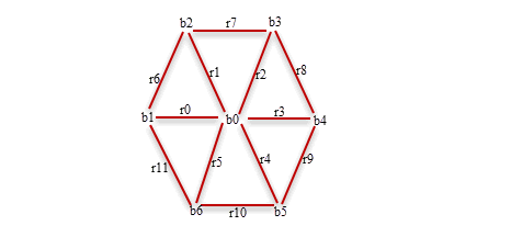
Figure 20-4 Example of lattice structure
You can use PK_GEOM_check to check lattice structures for invalidities. See PK_check_fault_t, for a list of faults that may be returned.
You can optionally choose to create a blended lattice using a number of options in PK_LATTICE_create_by_graph. Blending a lattice allows you to increase the stiffness of the lattice thereby improving its structural strength.
Lattices can be blended in the following ways:
Using the
lball_blend_type
and the
lball_blend_size
options, you can create a blended lattice whose lballs have the same blend size, where each lball’s blend radius is either a constant or a constant multiple of the lball’s radius. The
lball_blend_type
option has the following values:
|
The lattice has blends and each lball’s blend radius is equal to the blend size. This is illustrated in Figure 20-5. |
|
|
The lattice has blends and each lball’s blend radius is the product of the lball’s radius and the blend size. This is illustrated in Figure 20-5. |
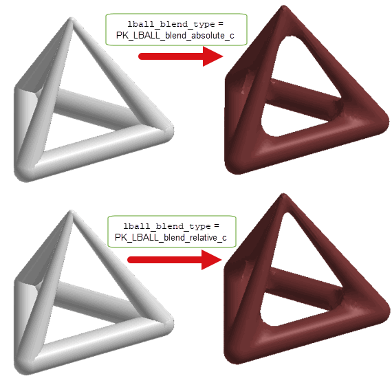
Figure 20-5 Blended lattices whose lballs have the same blend size
Alternatively you can vary the blend size of lballs within the lattice by using the
lball_blend_sizes
option in the
graph_reader
callback. In this case, each lball’s blend radius is the corresponding value in
lball_blend_sizes
, optionally multiplied by the lball’s radius depending on the value of the
lball_blend_type
option (see table in Section 20.5.1, “Blended lattices with lballs of the same blend size” for a list of these values).
Figure 20-6, illustrates where the blends are applied locally with smaller blend radii applied at the larger lballs. See Section 20.3, “Graph types” for more information on the graph reader callback function.
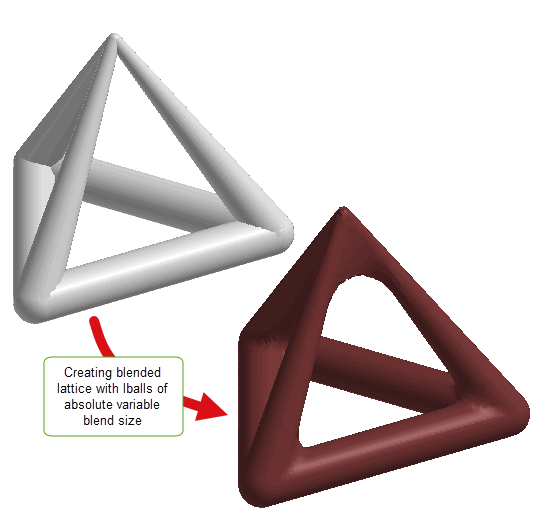
Figure 20-6 Blended lattice whose lballs have different blend sizes
You can create a new lattice from patterned repetitions of a supplied core lattice using PK_LATTICE_make_patterned.
|
Contains the standard form PK_SKEWBOX_sf_t which holds the data on the cell to be repeated. This structure also determines how neighbouring cell repetitions connect to each other. See PK_SKEWBOX_sf_t for more information on the standard form of a skewbox. |
|
|
Determines the number of repetitions of the |
|
|
Contains information about the type of pattern to be used. See Section 20.6.1, “Deforming the pattern” for more information. |
|
|
A user defined callback function used to deform the pattern. See Section 20.6.1, “Deforming the pattern” for more information. |
The
cell
, which contains the core input lattice that is to be repeated, tessellates to create a pattern of cells which come together to form a new lattice. This is illustrated in
Figure 20-7, with the
bound
option set to (-2 2) in all three directions.
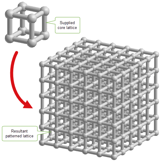
Figure 20-7 Creating a new lattice from a patterned repetition of a supplied lattice
Optionally, you can use the
form
option and/or the
callback
option to relocate and deform the supplied pattern. The
form
option specifies the type of pattern supplied along with the data of the pattern. The type can be one of the following values:
The
callback
option can be also be used to geometrically deform the supplied pattern. The option takes user supplied information to deform patterned positions.
Figure 20-8 shows a core lattice being deformed using the
callback
to create a patterned lattice, with the
bound
option set to (0 4) in two directions and (0 0) in the other direction. See the
PK Interface Programming Reference Manual for more information on the
callback
option.
Note: If both a
pattern
and a
callback
are supplied, the callback is applied after any deformation is applied from
pattern
. |
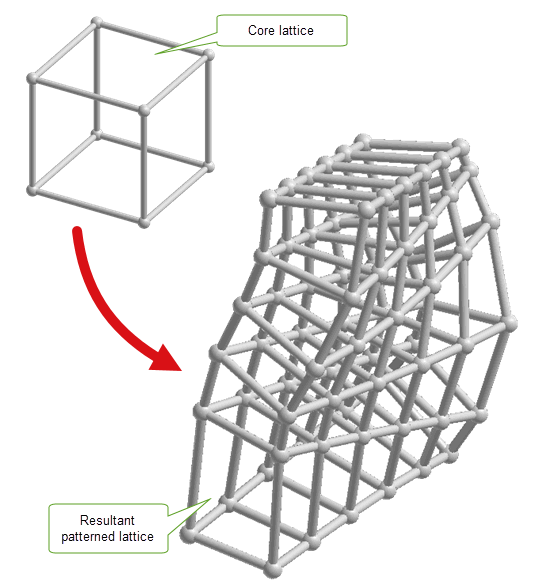
Figure 20-8 Creating a lattice by relocating and deforming a pattern using the
callback
option
You can use PK_BODY_make_patterned to create a lattice-like mesh body by patterning a facet body as illustrated in
Figure 20-9 with the
bound
option set to (-2 2) in all three directions. If you supply a sheet body then it must be open such that its laminar edges match neighbouring repetitions.This function has the same options as PK_LATTICE_make_patterned. For more information on these options, see Section 20.6, “Creating a lattice structure from a core lattice”.
|
Note: The input body must only contain facet geometry. |
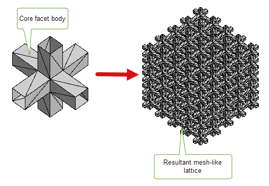
Figure 20-9 Creating a lattice-like mesh body
You can create a solid body from lattice geometry using PK_LATTICE_make_bodies. The solid body can have one or more closed mesh faces. See the PK Interface Programming Reference Manual for more information on this function.
The process of trimming or cutting down a lattice to fit a model, or a sub-set of a model, is referred to as clipping. You can clip a lattice with one or more clip entities using PK_LATTICE_clip. See Section 55.6, “Clipping Lattices”, for more information.
Parasolid provides the following functions for enquiring about lattices and their substructures:
|
Calls the given callback function for every lball in the given lattice |
|
|
Calls the given callback function for every lrod in the given lattice |
|
|
Returns a non axis-aligned bounding box of the given lattice. See Section 26.6.1.1, “Axis-aligned and non axis-aligned boxes” for more information. |
|
|
Returns the set of lattices that are attached to the given part as construction geometry |
| <<< Nominal Geometry | Chapters | Transformations >>> |