
 |
Tracking And Labelling |
| <<< PK Interface Programming Concepts | Chapters | Using Reports >>> |
This chapter is an introduction to the range of generic, customisable tools that Parasolid provides if you need to implement a mechanism that can accurately track the creation and manipulation of entities as you perform operations. Feature modelling applications can, for example, use these tools as fundamental components of a persistent labelling strategy.
This section provides an overview of the tools and sources of information that you can use to implement a tracking mechanism. Where applicable, references to additional dedicated material are also provided. Typically, you should consider using a number of the tools and sources described here; it is unlikely that you would be able to implement a complete tracking mechanism using only a single tool. The precise combination of tools that are best for your application depend on both the overall strategy you are following for tracking in your application, and the particular modelling operations you are using.
Most functions that change topological and geometric entities report information about those changes through their returned arguments. Those that don’t typically use the Parasolid report mechanism described in Section 10.2.2, “Reports”.
Tracking information can be returned in a number of ways, depending on the API, including:
Tracking information always returns new entities that have been created as the result of an operation, and can also include information regarding the original or seed entities from which a new entity has been derived, thereby allowing you to track a given entity’s provenance.
On completion, all Parasolid functions return information relating to the success or failure of the operation. This information can tell you about whether the function call failed completely (i.e. the operation did not complete), or about the status of the operation (i.e. the function completed, but may not have produced the expected outcome).
A Parasolid (PK) error occurs when a PK function fails and returns a non-zero error code (i.e., one that is different to PK_ERROR_no_errors). For example, calling the function PK_BODY_create_solid_cyl with negative
radius
or
height
returns PK_ERROR_distance_le_0. If an error such as this is returned, the values of any returned arguments are undefined and should not be used for tracking (or any other) purposes.
Even if a Parasolid function returns a zero error code (PK_ERROR_no_errors), it may also return a failure status code within the return arguments of the function if it has not been able to perform its task as intended, and needs to return a more detailed diagnosis of the problem. For example, if PK_BODY_fix_blends is called and two or more blends are set to overlap, the function returns PK_ERROR_no_errors but sets its
fault
argument to PK_blend_fault_overlap_c.
The Parasolid report mechanism is also used to return diagnostic information in the form of status codes: see Section 10.2.2, “Reports”, for an introduction to this mechanism.
See Chapter 120, “Error Handling”, for more information on handling errors returned by Parasolid functions.
A number of API functions return additional information through the report mechanism. This information can be used in the same way as tracking information returned by the API itself.
Where applicable, the PK Reference documentation for relevant functions indicates that the report mechanism is used for these purposes, and explains how to interpret the information returned. For example see the documentation for the
receive_compound
option in PK_PART_receive_o_t.
Parasolid reports are described in detail in Chapter 11, “Using Reports”.
When changes are made to an entity as a result of a modelling operation, a set of rules governs how the tags of the affected entities are affected.
You can make use of the rules that govern tag persistence within your application’s tracking mechanism, because they allow you to make certain assumptions in your application code when dealing with model changes resulting from modelling operations.
See Section 2.4.2.3, “Persistence of tags”, for more information about tag persistence.
Attributes are entities that provide a means for your application to associate additional information with a model. They can be modified automatically when changes are made to a model. You can attach attributes to topology and to any geometry that is incorporated into a model.
Attributes are fully customisable in terms of the information that they contain, the entities to which they may be attached and their behaviour under modelling operations.
When an entity is modified, the behaviour of an attribute associated with that entity depends on both of the following:
For example if a face with an attribute attached to it is split into two, the attribute may be deleted, persist on one of the resultant faces or be propagated to both of the resulting faces.
There are a set of seven pre-defined attribute classes. Each of these has a set of rules which governs how attributes of that class are modified under a set of standard low-level modelling operations.
See Chapter 94, “Attribute Definitions”, for information about attribute definitions.
See Chapter 95, “Attributes”, for information about attributes.
You can customise the behaviour of attributes when a model is modified in a particular way by using attribute callbacks. When a model is modified, you can use attribute callbacks to let your application watch (in the case of read only callbacks) the behaviour of an attribute or (in the case of normal callbacks) have full-decision making powers as to how that attribute should behave.
Due to their customisable nature (both in terms of content and behaviour), attributes and attribute callbacks can be key tools in your application’s tracking and labelling strategy.
Attributes are used extensively within Parasolid operations to mark and track changes to entities during a model change.
See Section 94.3, “Callback functions”, for more information on attribute callbacks.
If your application implements partitioned rollback (essential for a feature-based modelling application and highly recommended for all applications), you may find the information regarding entities which are new, changed or modified by the rollback (or roll-forward) operation is a useful source of tracking information.
This can be particularly useful in the context of changing a model feature in a feature modelling application which might involve rolling the partition back to a state immediately prior to the feature being created prior to editing.
See Section 97.2.4, “Rolling to a partition mark”, for more information.
The bulletin board can be used to track low level changes to a class or classes of entities (e.g. faces, edges) under a modelling or other model change. The sequence of changes reported by the bulletin board can be used by the application to trace the changes to individual entities during a modelling or other operation.
See Chapter 99, “Bulletin Board”, for more information about the bulletin board.
Tag persistence, the behaviour of attributes, the bulletin board and changes reported by rollback operations are all governed by low-level model changes such as split, merge, create, delete and change. These refer to binary and low-level changes to the model and therefore the changes may sometimes seem counter-intuitive when viewed purely from the perspective of the high-level modelling operation that is being performed. Often a sequence of low-level modelling operations chain together to form the changes made to the model under a particular API call.
With the exception of a very small number of APIs, the order of the returned entities is not guaranteed by Parasolid. This applies both within a particular version of Parasolid (including patch releases) and between different versions of Parasolid. Your application must not therefore rely on the order in which entities are returned from a function unless the API documentation specifically states that the order is guaranteed .
One example of such an exception is the order of faces returned from PK_BODY_ask_faces for solid primitives that have been created with the routines such as PK_BODY_create_solid_block. The ordering is described in Section 26.4.1.1, “The returned order of faces of primitive solid bodies”.
You can use enquiry functions to discover topological and geometric connectivity before or after a modelling operation. This strategy is usually used in conjunction with the other tools described in this chapter and forms a vital part of any persistent labelling strategy. APIs such as PK_BODY_ask_faces, PK_FACE_ask_edges, PK_BODY_ask_edges, PK_EDGE_ask_faces and PK_CURVE_ask_edges are just a small selection of the routines that you might want to use as part of such a strategy.
See Chapter 26, “Enquiry And Output Functions”, for more information.
As part of your application’s persistent labelling strategy, you may sometimes find it useful or necessary to store a three-space point along with a face or an edge in order to uniquely identify that entity. These additional points are typically referred to as help points in the Parasolid interface. To create or identify suitable help points, Parasolid provides a number of enquiry functions that let you determine a point on an edge or within a face, or let you enquire whether a given point lies within a face or on an edge.
See Chapter 26, “Enquiry And Output Functions”, for more information.
Appitems are a means by which you can associate a Parasolid tag with an entity in your application.
For more information see Chapter 93, “Identifying Application Data”.
User fields provide a means of associating a fixed-length byte array with each and every Parasolid entity. You can then store application specific information within the user-field associated with a given Parasolid entity.
See Section 115.6, “User fields”, for more information.
Persistent labelling, particularly in the context of a feature modelling application, can be implemented using a number of different approaches. The Parasolid tools described in this chapter offer low-level building blocks that can be utilised as essential components of an application's persistent labelling strategy. The tools are designed to provide flexibility, so as not to dictate that a particular approach must be implemented.
There are a number of academic papers on the topic of persistent labelling, a small selection of which are referenced below. We do not endorse or recommend any particular strategy over another.
This section describes a very simple example that demonstrates how to use the information returned by the Parasolid API to track information so that entities can be passed between different function calls in the course of a simple modelling session. The example demonstrates how to create a solid block from primitives, add an edge blend, and then a cylindrical boss. The stages involved in the process are as follows:
These stages are described in full in the rest of this section.
Throughout this example, function call diagrams illustrate the parameters that you need to provide to PK functions and the information that is returned by them. These diagrams illustrate how information is tracked throughout the modelling session, and how arguments are passed between functions. Figure 10-1 explains the layout of these diagrams. Each diagram contains the components listed below:

|
The function name is shown in bold in the central box of each diagram. |

|
Parameters that you pass into the function are shown at the top of the diagram. The argument name shown is the same as the field name used in the relevant entry of the PK Interface Programming Reference Manual. |

|
Information that is returned by the function is shown at the bottom of the diagram. The argument name shown is the same as the field name used in the relevant entry of the PK Interface Programming Reference Manual. |

|
Returned arguments that are reused in a subsequent function call within the example are indicated using a dashed arrow. In addition, if the argument is reused in a field with a different name, this name is shown in the diagram. |
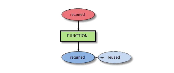
Figure 10-1 Template for function call diagrams
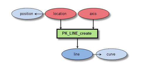
Figure 10-2 Function call to create a curve
First, you need to create a series of curves that will be used to form a profile. Since you are creating a simple block, the profile consists of four lines. You create these with four calls to PK_LINE_create, passing in a
location
(point) and an
axis
(direction) to each call via the
line_sf
standard form to create four unbounded lines that pass through the specified points in the given directions.
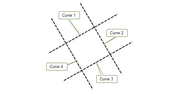
Figure 10-3 Creating lines to define the profile
The tags of the resultant curves are returned by each call to PK_LINE_create in the
line
return argument.
You need to use PK_CURVE_make_wire_body_2 to create a wire body from which the sheet profile will be completed. In order to do this, you need to find the interval of each line that defines boundary of the profile. This is done using PK_CURVE_parameterise_vector:
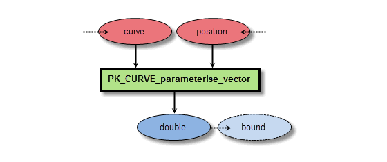
Figure 10-4 Function call to find a parameter on a curve
For each line in the profile boundary, call PK_CURVE_parameterise_vector twice (a total of 8 calls):
curve
) and one of the points (
position
) that the line passes through.
Each call returns the parameter (
double
) on the line of the given point. The interval of that line therefore comprises an array containing these two parameters.
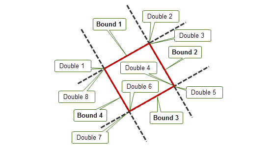
Figure 10-5 Creating lines to define the profile
To make a wire body, call PK_CURVE_make_wire_body_2, handing in the set of
curves
returned by each call to PK_LINE_create, and the set of
bounds
created by combining pairs of returned parameters from calls to PK_CURVE_parameterise_vector.
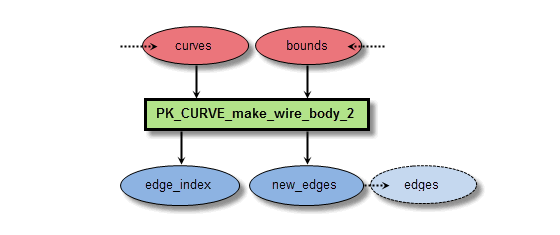
Figure 10-6 Function call to create a wire profile
PK_CURVE_make_wire_body_2 creates an edge for each curve received, and returns these in the array of
new_edges
. Because the function does not guarantee to return edges in the same order that their associated curves were received, it also returns the
edge_index
array, which maps returned
new_edges
to their original curves.
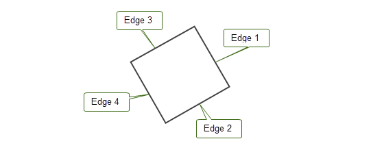
Figure 10-7 Creating a wire body profile
At this stage, you have a wire body which, if used as a profile in a sweep operation, would create a sheet body. Since you are creating a solid block, you first need to turn this wire body into a sheet. You do this by first adding a face, and then attaching a surface to the face.
To add a face to the wire profile, use PK_EDGE_make_faces_from_wire, which attaches faces to closed loops in a wire body.
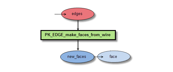
Figure 10-8 Function call to add a face to the wire profile
You need to pass this function an edge from each closed loop of the faces you want to create. In this simple case, a single edge from the
new_edges
returned by PK_CURVE_make_wire_body_2 should be passed in. In the more general case, you should use the
edge_index
array to compare
new_edges
returned by PK_CURVE_make_wire_body_2 with the lines returned by PK_LINE_create to ensure that you choose a single edge from each closed loop.

Figure 10-9 Function call to attach a surface to the profile’s face
PK_EDGE_make_faces_from_wire returns the new face created for the wire profile: you can pass this face into PK_FACE_attach_surf_fitting to create a suitable surface and attach it to the face, thereby completing the sheet profile you require.
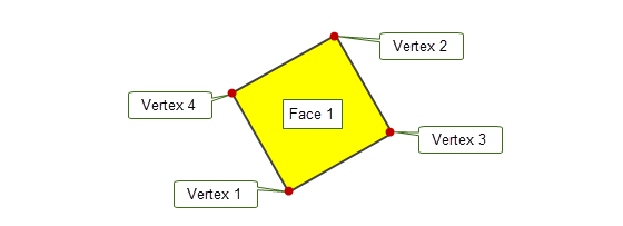
Figure 10-10 Creating a sheet profile from the wire body
In addition, pass the face to PK_FACE_ask_body to retrieve the sheet profile body itself. You will need to pass this body into several subsequent function calls.
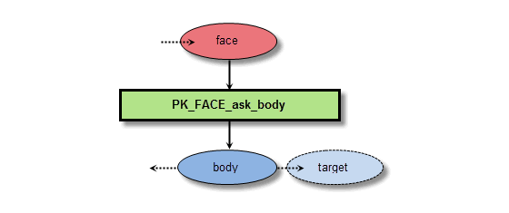
Figure 10-11 Function call to find the profile body
To create a solid body from the sheet profile you have created, use PK_BODY_sweep. This receives the profile body you have already created, together with a vector path that defines the direction of the sweep.
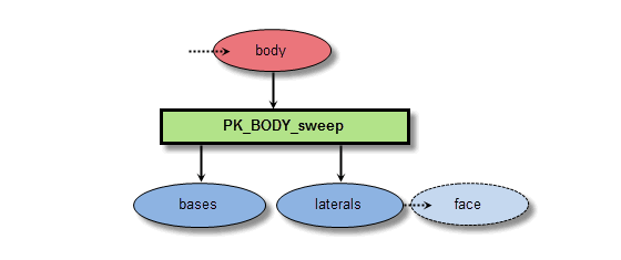
Figure 10-12 Function call to sweep the profile into a solid block
PK_BODY_sweep returns a number of laterals - new edges or faces created by the sweep operation, together with corresponding bases - the entities on the original profile from which these laterals were derived.
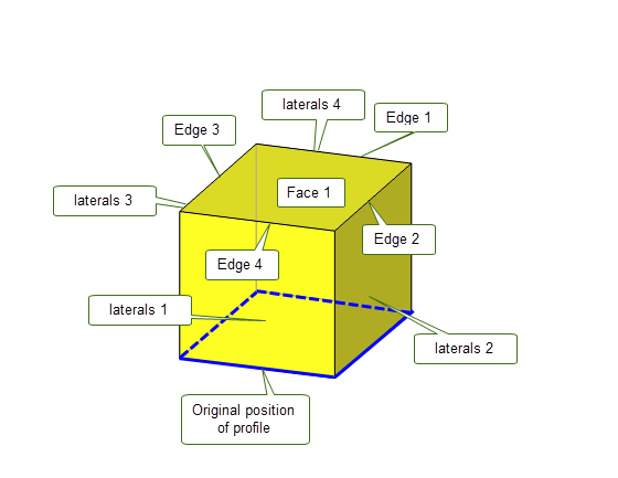
Figure 10-13 Sweeping the profile to form a solid
From this information, you can determine any entity in the swept body:
The next step is to use PK_FACE_ask_edges to identify the common edge between the 1st and 2nd lateral faces: this is the edge that you will blend.
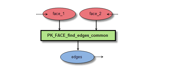
Figure 10-14 Function call to find the edge that lies between two laterals
To add a blend to an edge, pass the edge to PK_EDGE_set_blend_constant together with a blend
radius
.
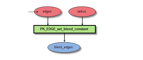
Figure 10-15 Function call to set an edge blend
Once set, you can fix the blend by passing the block to PK_BODY_fix_blends, which returns the new blend face in
blends
. The underlying faces from the original model associated with the new blend face are returned in
unders
.

Figure 10-16 Function call to fix a blend
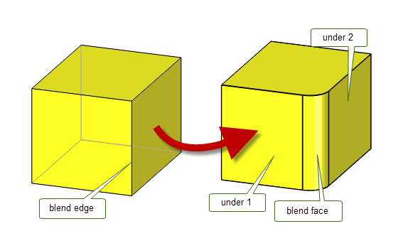
Figure 10-17 Creating a blend on an edge
Note: This simple example illustrates the blending of only a single edge. If several edges were blended, then each blended edge might have a different set of underlying faces. PK_BODY_fix_blends also provides the
tracking_type
option to give you closer control of preceisely what tracking information is returned in
unders
. In addition, the tags of the original edges that were blended are returned in
topols
, although these tags will generally be dead after the blend has been fixed, since the original unblended edges no longer exist. |
In the final stage, a cylindrical boss is added to the blended block you have already created. This is done by creating a cylinder and then performing a boolean unite between the cylinder and the blend block.
Use PK_BODY_create_solid_cyl to create a cylinder of a given radius, height, and position.
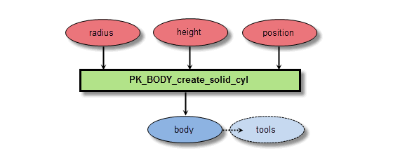
Figure 10-18 Function call to create a cylinder
Like other PK_BODY_create_... functions, PK_BODY_create_solid_cyl is a primitive creation function, so for the purposes of this example you can rely on the order in which PK_BODY_ask_faces returns faces from the cylinder to uniquely identify each of its faces.
|
Warning: In general, you should not rely on the order that entities are returned by PK functions. |
PK_BODY_create_solid_cyl returns the cylindrical
body
, which you can use as the tool in a call to PK_BODY_boolean_2, together with the blended block as the
target
.

Figure 10-19 Function call to unite the cylinder with the blended block
You can rely on tag persistence to discover the entities that the faces of the boss and the modified target faces were derived from. At this stage in the modelling session, all faces, edges, and vertices in the model can be uniquely identified.
|
Note: Rather than relying on tag persistence, a better implementation would use the tracking returns provided by PK_BODY_boolean_2 to track new edges in the final model rather than tag persistence. An even more robust implementation would use a more generic attribute labelling system (as outlined in Section 10.2.4), which would allow split and merge events to be accurately tracked for all topology classes. |
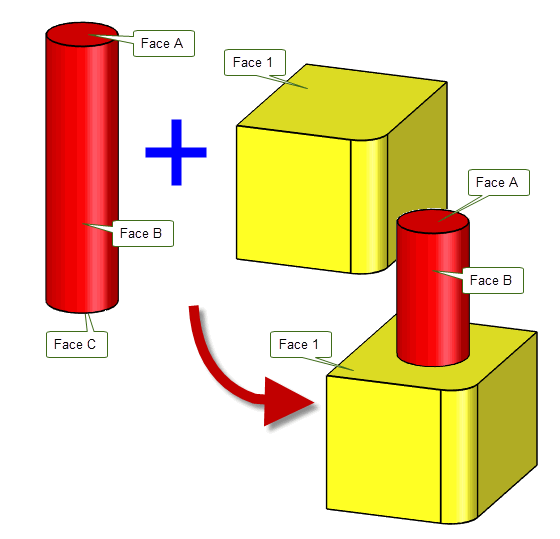
Figure 10-20 Uniting the block and the cylinder to create a boss
| <<< PK Interface Programming Concepts | Chapters | Using Reports >>> |