Entity Twisting
The api_twist_entity function and associated Scheme extensions are used to twist all or part of a body about a specified axis. Two positions are specified that represent the endpoints of the twist axis and the region of the body to twist. Two planes normal to the axis are located at the axis endpoints, and the region between these two planes defines the twist region.
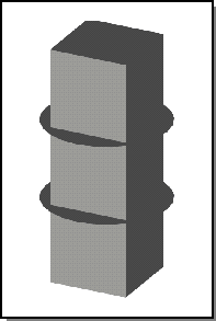
Figure. Defining the Twist Region
The above figure shows a simple box with a 1-by-1 base and height 3. The axis endpoints, Pos1 and Pos2, are on the middle axis at heights 1 and 2. The vector between these points determines the twisting axis. Pos1 and Pos2 also define the extent of the twist, as illustrated by the two discs shown in the figure. The body is twisted only between the two planes. The parts of the body above the top plane and below the bottom plane are simply rotated in order to maintain continuity with the twisted section.
Two angles can be specified (in radians for C++ and degrees for Scheme). The first angle, theta1, is usually 0, but can take other values where convenient. All points in front of (or below) the twist starting plane are rotated by theta1. Likewise, all points in back of (or above) the twist ending plane are rotated by the second angle, theta2. For points between the two twist planes, the degree of twist is found by interpolating between theta1 and theta2. The interpolation function uses a linear, cubic, or quintic polynomial to obtain G0, G1, or G2 continuity between twisted and untwisted sections.
The axis endpoints can be inside or outside of the body and do not need to be aligned with the axis of the body. The two angle values, theta1 and theta2, can be any positive or negative value. Absolute values of the angle greater than 360 (or 2*pi) result in multiple turnings.
The entity:twist Scheme command uses the same parameters as the api_twist_entity.
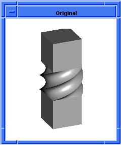
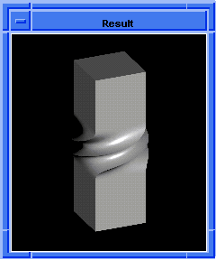
Figure. Continuity of 0 and 2
The above figure shows the result of twisting the lower and upper planes of the box by 50 and 230 degrees, respectively. The left figure shows G0 continuity, while the right shows G2 continuity.
The syntax for the Scheme command is
| (entity:twist body pos1 axis1 pos2 theta2 continuity) |
Scheme Example
(define box (solid:block (position -.5 -.5 -1) (position .5 .5 2 ))) (entity:set-color box 3) (entity:twist box (position 0 0 0) (position 0 0 1) 50 230 0) (roll) (entity:twist box (position 0 0 0) (position 0 0 1) 50 230 2) |
Figure. Twisting a Drill Bit shows the result of using a twist to create a drill bit. A cylinder is notched with two smaller cylinders. The resulting blank is twisted about its axis. The start and end positions are specified in such a way that the entire body is twisted. The original body and the twisted body are shown.
Scheme Example
(define c1 (solid:cylinder (position 0 0 0) (position 0 0 40) 5)) ;; c1 (define c2 (solid:cylinder (position 0 -5 0) (position 0 -5 40) 3)) (define c3 (solid:cylinder (position 0 5 0) (position 0 5 40) 3)) ;; c2 (define blank (solid:subtract c1 c2)) ;; blank (define blank (solid:subtract c1 c3)) ;; blank ; Twist the blank. (define screw (entity:twist blank (position 0 -10 5) (position 0 10 35) 0 (law:eval "0.25*360") 0)) ;; screw |
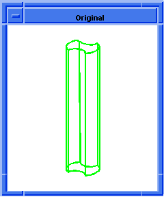
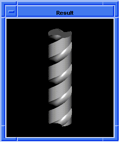
Figure. Twisting a Drill Bit
Figure. Baluster shows the result of using a twist to create a staircase baluster. Four overlapping cylinders are twisted about a centerline axis.
Scheme Example
(define inset1 .35) (define inset2 (- 1.0 inset1)) (define radius .35) (define bottom_box (solid:block (position 0 0 0) (position 1 2 1))) (define c1 (solid:cylinder (position inset1 2 inset1 ) (position inset1 12 inset1) radius)) (define c2 (solid:cylinder (position inset2 2 inset1 ) (position inset2 12 inset1) radius)) (define c3 (solid:cylinder (position inset1 2 inset2 ) (position inset1 12 inset2 ) radius)) (define c4 (solid:cylinder (position inset2 2 inset2 ) (position inset2 12 inset2 ) radius)) (define top_box (solid:block (position 0 12 0) (position 1 14 1))) (define pillar (bool:unite bottom_box top_box c1 c2 c3 c4)) (entity:twist pillar (position .5 2 .5) (position .5 12 .5) 0 720 0) |
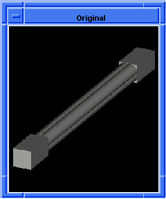
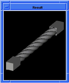
Figure. Baluster
[Top]
© 1989-2007 Spatial Corp., a Dassault Systèmes company. All rights reserved.