Scheme Extensions |
|
|
|
Technical Article |
| Scheme is a public domain programming language, based on the LISP language,
that uses an interpreter to run commands. ACIS provides extensions (written in
C++) to the native Scheme language that can be used by an application to
interact with ACIS through its Scheme Interpreter. The C++ source files for
ACIS Scheme extensions are provided with the product. Spatial's Scheme based
demonstration application, Scheme ACIS Interface Driver Extension (Scheme
AIDE), also uses these Scheme extensions and the Scheme Interpreter.
|
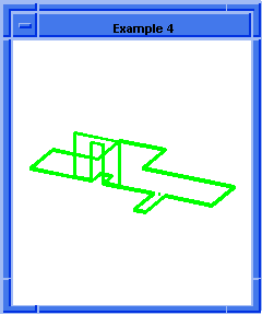
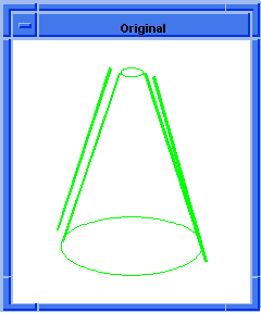
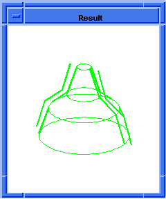
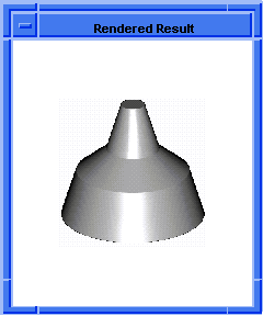
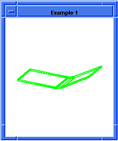
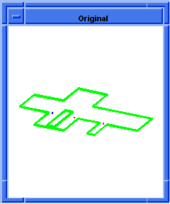
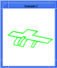
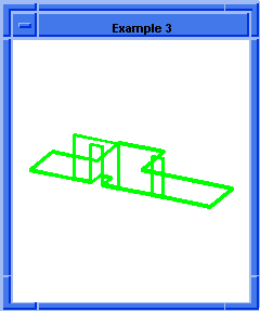
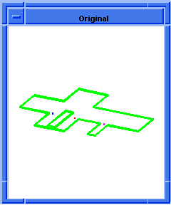
entity:bend
- Action
-
Modifies an entity or list of entities by bending it around an axis.
-
Filename
-
scm/scmext/warp/bend_scm.cpp
-
APIs
-
api_bend_entity,
api_part_note_state,
api_pm_start_state
-
Syntax
-
(entity:bend ent-list neutral-root bending-axis
bending-direction bend-radius
[bend-angle [bend-width
[center-bend-flag [bend-position*]]]])
-
Arg Types
-
-
Returns
-
entity
| (entity
...)
Description
Neutral-root,
bending-axis, and
bending-direction
define a neutral plane for the bending operation. A neutral plane is the
location where the material is not stretched or compressed during bending. The
material above the neutral plane (along bending direction) is compressed and
the material below the neutral plane is stretched. The location of a neutral
plane varies with the type of material to be bent.
- Arguments
-
neutral-root
is a position that defines the location of neutral plane.
-
bending-axis
is a gvector that defines the rotational axis of bending action.
-
bending-direction
is auxiliary gvector that is used to define a bending plane.
-
The bending axis, denoted by
bending-axis, and the bending
direction, denoted by
bending-direction, define a bending
plane with normal vector
bending-axis
x
bending-direction. The bending axis
and bending direction should be perpendicular to each other. The cross product
of these two vectors defines the positive and negative sides of the entity to
be bent.
-
bend-radius
is a real number that specifies the radius to the neutral plane.
-
bend-angle
(optional) is the angle in degrees that specifies the amount to bend.
-
bend-width
(optional) is the width of bend region. The bend-radius, bend-angle, and
bend-width are used to determine the region to be bent. Because only two
parameters are independent, bend-width can be optional. Assigning zero or
negative values to any of the three parameters implies that the parameter is
skipped. It is always desirable to use just two of the three parameters.
However, if only the bend-radius is given, the entire entity is bent. These
parameters are related by:
bend-width=bend-radius*bend-angle*PI/180
-
center-bend-flag
(optional) is a Boolean type to specify final orientation, i.e., center bend or
fix end bend. The
center-bend-flag
is used to control the final orientation of the bend entity. If
center-bend-flag
is set to #t, material at both sides of the bending plane are equally bend by
half of the
bend-angle. If the
center-bend-flag
is not set or set to #f, the negative side is fixed, i.e., only the positive
side is bent by
bend-angle. This mode is called fixed
end bending.
-
bend-position*
(optional) specifies the portions of the entity to bend. The asterisk (*) means
one or more positions can be defined. The positions must be within the
components to be bent or on their faces. Several bend positions can be
specified to localize bending operation. The specified bend positions are
tested to determine if they are within the bending region. If all bend
positions are outside of the bending region or outside the entity and its
faces, no bending is performed.
[Top]
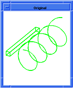
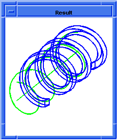
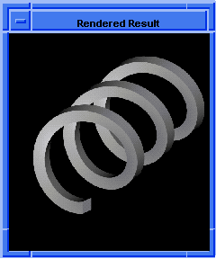
entity:bend-to-curve
- Action
-
Modifies an entity by bending it to a curve.
-
Filename
-
scm/scmext/warp/bend_to_curve_scm.cpp
-
APIs
-
api_part_note_state,
api_pm_start_state,
api_bend_to_curve_entity
-
Syntax
-
(entity:bend-to-curve body start end initial-rail
edge final-rail)
-
Arg Types
-
-
Returns
-
entity
-
Arguments
-
body
is one of the entity of a Scheme Component.
-
start
gives the start position for bending the curve.
-
end
gives the end position for bending the curve.
-
initial-rail
is a gvector.
-
edge
is an edge of the entity.
-
final-rail
is a law.
[Top]
entity:simplify
- Action
-
Simplifies the faces and edges of a body or the face and edges of a face.
-
Filename
-
scm/scmext/warp/warp_scm.cpp
-
APIs
-
api_simplify_entity
-
Syntax
-
(entity:simplify ent-list [acis-opts])
-
Arg Types
-
-
Returns
-
entity
| (entity
...)
Description
The face(s) and edges of an entity (body or face) are replaced with analytic
surfaces and curves, if possible. Otherwise, they are replaced with their
B-spline approximations.
- Arguments
-
ent-list
gives the list of entities that can be either body or face.
-
acis-opts
contains versioning and journaling information.
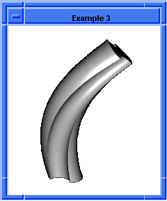
; entity:simplify
; Create the geometry to illustrate command.
(option:set "match_paren" #f)
;; #t
(cond (( = 0 (length (part:views))) (view:gl)))
;; #f
(define view (view:edges #t))
;; view
(define color (view:set-bg-color 7))
;; color
(part:clear)
;; #t
(define profile (edge:ellipse
(position 0 0 0) (gvector 0 0 1)10))
;; profile
(define opts (sweep:options "draft_law" "sin(x)"))
;; opts
(define sweep (sweep:law profile
(gvector 0 0 10) opts))
;; sweep
(define zoom (zoom-all))
;; zoom
(face:types)
; entity:(entity 3 1)
; face:(entity 4 1) face_type:sweepsur-spline
; face:(entity 5 1) face_type:Plane
; face:(entity 6 1) face_type:Plane
;; #t
; simplify the entity
(define simplify (entity:simplify sweep))
;; simplify
; show that the faces have been simplified.
(face:types)
; entity:(entity 3 1)
; face:(entity 4 1) face_type:exactsur-spline
; face:(entity 5 1) face_type:Plane
; face:(entity 6 1) face_type:Plane
;; #t
|
[Top]
entity:stretch
- Action
-
Creates a stretch for a given region of a body along the given axis.
-
Filename
-
scm/scmext/warp/stretch_scm.cpp
-
APIs
-
api_part_note_state,
api_pm_start_state,
api_stretch_entity
-
Syntax
-
(entity:stretch body position1 position2 distance1 distance2 continuity)
-
Arg Types
-
-
Returns
-
entity
Description
Entity stretching is a specialized space warping operation. The
position1
and
position2
arguments represent endpoints of the axis along which stretching is to be
performed, and can be either inside or outside the body. The region within
which stretching is to occur is bounded by the two planes through
position1
and
position2, and normal to this axis.
The
distance1
and
distance2
parameters are real numbers that specify the translations of the non-stretched
portions of the body. Typically,
distance1
is chosen to be 0, indicating that the portion of the body below the stretch's
starting region retains its position. If a nonzero value for
distance1
is specified, on the other hand, the entire body is translated along the
stretch axis by the given distance before the stretch is performed.
Let heightA be the distance between
position1
and
position2.
Let heightB be heightA + (distance2
-
distance1).
Let heightR be heightB/heightA.
Then heightR represents the amount of scaling to apply to the stretch region of
the body, along the stretch axis. (If heightR=1, therefore, no stretching or
scaling need be applied.)
The
continuity
value can be 0 or 1, and refers to G0 and G1 continuity between the stretched
and unstretched sections. The interpolation function uses a linear polynomial
to obtain G0 continuity. To obtain G1 continuity, it uses a piece of a sine
function. (The advantage of the sine function over a degree-3 polynomial is
that its inverse is well-defined.)
- Arguments
-
body
specifies the body to be stretched.
-
position1
and
position2 represent the endpoints
of an axis along which stretching is to be performed and can be either inside
or outside the body.
-
distance1
and
distance2
are real parameters that specify the offset distances at the start and end of
the stretch axis, respectively.
-
continuity
specifies the continuity (G0 and G1) required of the stretch.
[Top]
entity:twist
- Action
-
Creates a twist for a given region of a body about an axis by the specified
amount.
-
Filename
-
scm/scmext/warp/twist_scm.cpp
-
APIs
-
api_part_note_state,
api_pm_start_state,
api_twist_entity
-
Syntax
-
(entity:twist body position1 position2 theta1 theta2 continuity)
-
Arg Types
-
-
Returns
-
entity
Description
Entity twisting is a specialized space warping operation. The
position1
and
position2
are of type position. They represent endpoints of an axis about which twisting
is to be performed and can be either inside or outside the body. Two planes are
formed at the
position1
and
position2
positions which are normal to the axis. They specify the region of the body
where twisting is to occur.
The
theta1
and
theta2
parameters are real numbers that specify in degrees the orientation of the
non-twisted portions of the body. Typically,
theta1
is 0, meaning that the portion of the body below the twist's starting region
retains its orientation to the coordinate system. If a nonzero value for theta1
is specified, the entire body is transformed about the axis by the given amount
before performing the twist.
The difference between
theta1
and
theta2
represents the amount in degrees that the twist region is warped around the
axis. Both
theta1
and
theta2
can be greater than or multiples of +/- 360 degrees to provide more turns in
the twisting region.
The
continuity
value can be 0, 1, or 2 and refer to G0, G1, and G2 continuity. The
interpolation function uses a linear, cubic, or quintic polynomial to obtain
G0, G1, or G2 continuity between twisted and untwisted sections.
- Arguments
-
body
gives the entity of a Scheme Component.
-
position1
and
position2
represent endpoints of an axis about which twisting is to be performed and can
be either inside or outside the body.
-
theta1
and
theta2
are real numbers that specify in degrees the orientation of the non-twisted
portions of the body.
-
continuity
value can be 0, 1, or 2 and refer to G0, G1, and G2 continuity.
[Top]
law:warp
- Action
-
Modifies an entity or list of entities according to a given input law.
-
Filename
-
scm/scmext/warp/warp_scm.cpp
-
APIs
-
api_space_warp
-
Syntax
-
(law:warp ent-list law)
-
Arg Types
-
-
Returns
-
entity
| (entity
...)
-
Arguments
-
ent-list
gives the list of entities of a Scheme Component.
-
law
is an input law that specifies how the entity should be modified.
[Top]
© 1989-2007 Spatial Corp., a Dassault Systèmes company. All rights reserved.
![]()
![]()
![]()
![]()
