The Healing Component (HEAL) contains API functions that can be used to fix models imported from other modeling systems into ACIS in order to make them usable in ACIS. When geometry is created in some other modeling system and translated into an ACIS model, such a model may be imprecise due to the inherent limitations of their parent systems, or due to limitations of data transfer through neutral file formats. This leads to problems such as gaps between entities, and the absence of connectivity information (topology).
The Healing Component (HEAL) contains API functions to detect and correct such problems. HEAL is intended as a foundation on which an application can build a complete healing strategy. The HEAL functionality is available through both a C++ interface (APIs and classes) and a Scheme interface (Scheme extensions).
HEAL is not a translator from another modeling system into ACIS. The model must already exist in ACIS format (for example, in a SAT file) before being healed. HEAL may not be able to correct all of the problems that may exist in a model, but it will detect and correct a large percentage of them.
The features of HEAL include:
- Provides user-controllable tolerances for efficient healing
- Simplifies geometry by converting spline data to analytic data wherever possible
- Stitches faces together in the absence of connectivity (topology) information
- Provides functionality to tighten gaps in the model to a desired tightness
- Supports tightening of analytic and spline smooth edges
- Supports edges that could not be tightened after being converted into tolerant edges
The contents of this section include:
- Recommended Healing Workflow
- Automatic Healing
- Geometry Simplification
- Stitching
- Tightening Gaps
- Healing Tolerances used in api_hh_auto_heal
- Limitations
Recommended Healing Workflow
The following steps describe the recommended healing workflow that one can use on models translated into ACIS from external file formats:
Step 1: Tolerant Stitching (call api_stitch with tolerant_stitch_options)
Models translated into ACIS from external file formats may have the connectivity information (topology) absent (models having free FACEs), or incomplete (partially open models). A model in such a state needs to have the topology built up first before any solid modeling operations are carried on it. In such a case, users can use api_stitch in "Tolerant Stitching" mode to stitch or sew free FACEs, even if they are not close within SPAresabs but are close within the user-specified maximum stitch tolerance, to make solids or sheet models.
In addition to the absence of connectivity information, the incoming model data very often contain duplicate or partially coincident FACEs (FACE pair that are "back-to-back"). This is an illegal configuration for Tolerant stitching. However, api_stitch in "Tolerant Stitching" mode, can report back the coincident faces that it encounters during the stitching process. Customers should check for coincident face errors after stitching, and then check for the coincident faces reported by the tolerant_stitch_options object passed into api_stitch. (For more details, refer to the Tolerant stitching Technical Article in the online help for Stitch Component.) If found, then that region of faces needs to be corrected by the user and tolerant stitching should be done again. The user may need to keep retrying this step until no coincident faces are detected anymore.
One should set max-stitch-tol such that it is bigger than the size of expected maximum gap between faces to be stitched. Further it should be smaller than the minimum feature size in the model. This is important because api_stitch might remove edges smaller than the supplied max-stitch-tol. The max-stitch-tol value can be set using the method tolerant_stitch_options::set_max_stitch_tol().
Step 2: Simplification (call api_simplify_entity)
The incoming models often contain curves and surfaces that appear analytic when displayed on a screen, but are actually represented as splines. Simplification of such geometry to analytics results in a reduction of data size and speed improvements in geometric operations. If the customer downstream application permits the presence of analytic curves and surfaces in the model then, api_simplify_entity with user defined simplification tolerance can be used to achieve the above mentioned purpose.
A user can set the simplification tolerance to a value based on the needs of the downstream application. Note that since simplification causes a change in surface shape within the supplied tolerance, there can be gaps of that size introduced in the model after simplification. So if the user desires the gaps in the model to be within a certain value, then that value could be the best value to use as simplification tolerance.
Step 3: Tighten Gaps to desired tightness (call api_tighten_gaps)
Models coming from external file formats may have gaps bigger than SPAresabs. ACIS is able to handle such gaps using tolerant modeling. However there is no upper limit on the tolerances of the TEDGEs and TVERTEXs in ACIS. A customer application (like one for manufacturing) may need the gaps in the model to be tight within a certain application specific tolerance value (that would typically be a few orders looser than SPAresabs, for model units of cm, SPAresabs = 100 Angstroms!). So api_tighten_gaps is meant for customers whose downstream operations (like manufacturing) would desire the gaps in TEDGEs and TVERTEXs in their models to be within a certain limit. The api_tighten_gaps attempts to tighten gaps in the BODY that are bigger than supplied "desired_gap_tightness" value. One should set this value to the desired manufacturability tolerance of the application.
Notes:
- This healing workflow does not repair topological and geometric invalidities. It is expected that the model given as input to the workflow checks good at level 30 with the options "r14_checks" and "check_discont" enabled.
- Users should check for spurious short EDGEs and sliver FACEs in the models translated into ACIS, and remove them before calling "Healing Workflow" on them. The detection and removal of short EDGEs and sliver FACEs in the models cannot be automated, because it is not possible to automatically know if a short edge is genuine/intentional or spurious. It is advisable that a user interactively reviews all short EDGEs and sliver FACEs in a model by making use of ACIS APIs api_detect_short_edges followed by api_detect_sliver_faces, and removes those that are spurious. Both these APIs take in a sliver detection tolerance. As a rule of thumb, all genuine EDGEs and FACEs in a model are at least an order larger than the maximum gap in the model (because the size of a feature in a model cannot normally be smaller than the resolution of a modeler). Any EDGE or FACE smaller than that is a candidate for being spurious. APIs api_detect_short_edges and api_detect_sliver_faces, are capable of removing sliver EDGEs and FACEs. If short EDGEs and sliver FACEs are removed automatically, then there is a chance that even genuine EDGEs and FACEs might be removed.
- It is preferable to do this sliver removal step before doing the "Healing Workflow". However if it not possible to know the maximum gap in the model beforehand, then it can alternatively be done after the stitching step in the "Healing Workflow". After stitching, the largest tolerance in the model (refer tolerant:report gives the biggest gap in the model.
- If the EDGE and FACE geometry in the model being passed into this workflow is non-C1, then this workflow might give undesirable results. It is advisable to fix such discontinuities upstream before passing those into the workflow. The API api_check_entity, used with the "check_discont" option turned on, can help locate non-C1 geometry. Refer to the documentation of api_check_entity for more details.
Figure. Healing Workflow illustrates the above workflow:
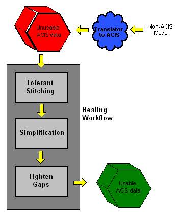
Figure. Healing Workflow
Refer to the use case Sample Code to Demonstrate How to Execute Healing Workflow for details about how to implement this workflow.
Automatic Healing
The entire healing process may be performed in one operation, called automatic healing (autoheal). However this operation tries to tighten all gaps bigger than SPAresabs. This may not be a practical requirement (for model units of cm, SPAresabs = 100 Angstroms!). So it is recommended that the above-mentioned healing workflow be used rather than autoheal.
Automatic healing (api_hh_auto_heal) determines appropriate tolerances to use in each healing phase/subphase by first analyzing the input model. The steps taken in automatic healing are:
- Preprocess the body to be healed.
- Test and simplify any spline surfaces that meet the testing criteria. For each spline surface, if it can be represented by an analytic surface within the simplification tolerance, then replace the spline surface with the appropriate analytic surface (plane, cylinder, etc.).
- If the input consists of faces, determine a stitching tolerance, and attempt to stitch the faces into either a complete solid or a single sheet body.
- Analyze and heal the stitched geometry (build geometry to repair the model).
- Postprocess the healed body.
Information about the automatic healing process is returned. This includes such things as statistics of the various healing phases, the results of automatic healing (for example, whether the model was fully healed, partially healed, stitched only, or if automatic healing failed), and an analysis of the healed model.
Autoheal does not terminate the body after healing. This preserves the healing attributes after autoheal, which allows applications to test for unhealed edges, vertices, etc. (Refer to the C++ implementation of the Scheme extensions for examples.) It is recommended that the healing attributes be removed (using api_terminate_healing) before saving the healed body to a SAT file.
Geometry Simplification
The incoming models often contain surfaces that appear analytic when displayed on a screen, but are actually represented as splines. In the geometry simplification phase, such spline surfaces are converted to corresponding analytic forms (for example, plane, cone, torus, or sphere) wherever possible. Geometry simplification results in a reduction of data size and speed improvements in geometric operations.
In the healing workflow the API api_simplify_entity can be used for geometry simplification. Additional APIs are available for forcing geometry simplification to a specific type of analytic. These APIs are intended to be used for standalone geometry simplification, rather than as part of the healing process. These API functions should be used with caution, since these functions do not guarantee that the output model would be valid. The APIs are:
api_hh_force_simplify_to_plane
Fits the best plane to the spline surface of the input face. Replaces the geometry of the face with the calculated plane.
api_hh_force_simplify_to_cylinder
Fits the best cylinder to the spline surface of the input face. Replaces the geometry of the face with the calculated cylinder.
Fits the best cone to the spline surface of the input face. Replaces the geometry of the face with the calculated cone.
api_hh_force_simplify_to_sphere
Fits the best sphere to the spline surface of the input face. Replaces the geometry of the face with the calculated sphere.
api_hh_force_simplify_to_torus
Fits the best torus to the spline surface of the input face. Replaces the geometry of the face with the calculated torus.
A note about usage of api_hh_simplify_auto: When calling geometry simplification explicitly using api_hh_simplify_auto or api_hh_simplify_analyze, curves can also be simplified. This is done by calling these routines with an hh_simplify_options object with the "do_curve_simplification" parameter set to "1". This causes the simplify routine to convert straight, circular, and elliptical non-analytic curves to their corresponding analytics. Tolerance and Maximum Allowed Radius (for circular and elliptical curves) parameters can also be set using this object. When used as part of autoheal, curve simplification is not performed at the same time as surface simplification (that is, before geometry building), rather it is performed during post-processing with a tolerance of resabs when the AcisVersion value is R11 or greater.
Incoming data has surfaces and curves that often appear analytic on the screen but are actually represented as splines. Geometric simplification converts such spline surfaces and curves to analytic surfaces and curves wherever possible. This simplification converts splines to the corresponding analytic representations such as line, ellipse, plane, cone, torus, and sphere.
ACIS offers these methods for geometry simplification:
Note: Former geometry simplification APIs, api_simplify_body and api_simplify_face, have been deprecated and are not to be used.
The API api_simplify_entity accepts an ENTITY pointer. The ENTITY pointer passed to the API may point to a BODY, LUMP, SHELL, FACE, WIRE, EDGE, or TEDGE. api_simplify_entity attempts to replace the geometry of the faces and edges in the entity with geometrically equivalent analytic surfaces and curves. Furthermore, this API attempts to perform the simplification within the user-specified tolerance. Also, api_simplify_entity provides an option (OFF by default) to replace the existing procedural geometry by its approximate B-Spline geometry in case simplification with analytic geometry is not possible within the user-specified tolerance.
During the processing stage, if api_simplify_entity finds that simplification of a particular surface or a curve may result in an entity with invalidities (that is, an entity that cannot be fixed by making it tolerant), then the API will refuse to simplify that particular surface or curve. This is the default behavior of the API. However, api_simplify_entity provides an option to force simplification, in which case the API proceeds to simplify the surface or curve (if possible within the user-specified tolerance) even if simplification may result in invalidities in the entity.
The API api_hh_simplify_auto is one of the phases of healing recommended for use only in conjunction with other phases of healing in the following sequence:
- api_hh_init_body_for_healing
- api_hh_preprocess
- api_hh_simplify_auto
- api_hh_stitch_auto (if required)
- api_hh_geombuild_auto (if required)
- api_hh_postprocess
- api_hh_end_body_for_healing
Therefore, api_hh_simplify_auto cannot be used as a stand alone API for simplification. For more details on api_hh_simplify_auto, refer to the documentation of api_hh_simplify_auto.
The API api_simplify_entity is failsafe, but the other simplification APIs are not failsafe. For more details on the failsafe behavior, refer to the section "Failsafe Behavior".
You may control the behavior of api_simplify_entity by setting the parameters in an object of simplify_options class and having them pass into the API. The parameters that can be set are detailed in the documentation of api_simplify_entity.
Sample Code to Demonstrate the Use of api_simplify_entity
This section contains snippets of C++ code to illustrate how to typically use api_simplify_entity. These snippets are designed to be very simple starting points for developing your own code - they are not complete, compiling and runtime programs.
| #include "entity_simplify.hxx" // User function logical user-function-to-simplify-entity (ENTITY* entity_to_simplify, // This entity can only be BODY, LUMP, SHELL, // FACE, WIRE, EDGE or TEDGE ... // other arguments ) { ... // Create default simplify_options object simplify_options simp_opts; if (/* user defined tolerance needed */) { // Default tolerance used by api_simplify_entity is SPAresabs. // If needed, it can be changed by the following code double tol = user-function-to-get-required-tolerance(); simp_opts.set_simplification_tol(tol); } if (/* surface simplification not needed */) { // By default surface simplification is ON (TRUE) in api_simplify_entity // If needed, it can be changed by the following code simp_opts.set_do_surface_simplification(0); } if (/* curve simplification not needed */) { // By default curve simplification is ON (TRUE) in api_simplify_entity // If needed, it can be changed by the following code simp_opts.set_do_curve_simplification(0); } if (/* force simplification needed */) { // During its processing, if api_simplify_entity finds that simplification // of a particular surface or a curve would result in an entity with // invalidities (those which cannot be fixed by making the entity tolerant), // then the API will refuse to simplify that particular surface or curve. // This is the default behavior of the API. api_simplify_entity however // provides the user with an option to force simplification, in which case // the API would go ahead and simplify the surface or curve (if possible // within the user-specified tolerance) even if simplification would result // in invalidities in the entity. If needed, it can be changed by the following // code simp_opts.set_do_force_simplification(1); } if (/* procedural geometry is to be replaced by approximate B-Spline geometry.*/) { // If during simplification the API is not able to find an appropriate analytic // geometry for the FACE or EDGE, the API gives user an option to replace // procedural geometry of an EDGE or a FACE by the approximate B-Spline geometry. // By default the API does not replace the procedural geometry of an EDGE or a // FACE by the approximate B-Spline geometry. simp_opts.set_do_approximate(1); } // Keep the pointer to the old entity, since the api_simplify_entity may delete the // given entity and create a new one if needed (for example, when the user just passes // one EDGE pointer as an argument to the API, there is a possibility that the edge gets // simplified and is made toelrant. In this case the API will delete the incoming EDGE and // return the new TEDGE pointer that replaces the EDGE pointer). ENTITY* old_entity = entity_to_simplify; // Make the careful option OFF to enable failsafe behavior. // Note: By default the "careful" option is already OFF option_header *careful_opt = find_option("careful"); if (NULL != careful_opt) { careful_opt->push(FALSE); } outcome result_of_simplify = api_simplify_entity (entity_to_simplify, &simp_opts); if (NULL != careful_opt) { careful_opt->pop(); } if ( !result_of_simplify.ok() ) { // User may want to know about the fatal error due to which the API failed. error_info* einf = result_of_simplify.get_error_info(); // User code to report information on errors. A sample function // "display_problems_encountered" for such reporting is given at the bottom // of the code snippet. display_problems_encountered(einf); // Reasons for error if (einf->has_reasons()) { // User code to mention that the following are reasons for the error, // the user may print as printf("Following are the reasons for the error: \n"); // error_info_list owns all the error_info objects inside it and cleans // them up on destruction. User need not worry about memory cleanup of // the error_info objects. error_info_list reasons_eil; einf->reasons(reasons_eil); const error_info* reason_einf = NULL; for ( reasons_eil.init(); NULL != (reason_einf = reasons_eil.next()); ) { display_problems_encountered(reason_einf); } } // User code to handle of failure and exit ... } if (old_entity != entity_to_simplify) { // User code to handle new entity created by api_simplify_entity // For example, the user may want to substitute the old entity // pointer with the new one in the application's register. user-function-to-register-new-entity(old_entity, entity_to_simplify); } // Problem reporting by API. // API succeeded (either partially or fully) if this point is reached error_info_list eil; result_of_simplify.get_error_info_list(eil); const error_info* einf = NULL; for ( eil.init(); NULL != (einf = eil.next()); ) { // User code to report information on problems. A sample function // "display_problems_encountered" for such reporting is given at // the bottom of the code snippet. display_problems_encountered(einf); // Reasons for the problem if (einf->has_reasons()) { // User code to mention that the following are reasons for the problem, // the user may print as printf("Following are the reasons for the problem: \n"); // error_info_list owns all the error_info objects inside it and cleans // them up on destruction. User need not worry about memory cleanup of // the error_info objects. error_info_list reasons_eil; einf->reasons(reasons_eil); const error_info* reason_einf = NULL; for ( reasons_eil.init(); NULL != (reason_einf = reasons_eil.next()); ) { display_problems_encountered(reason_einf); } } } } // Utility function for displaying entity_error_info based problems encountered by API void display_problems_encountered(const error_info *einf) { if ( NULL == einf ) { return;} char const *err_message = einf->error_message(); spa_outcome_severity_type err_severity = einf->severity(); // User code to display message and severity // for example, the user may do the following printf("Problem encountered: %s\n", err_message); if (SPA_OUTCOME_FATAL == err_severity) // Represents a fatal error { printf("Severity: FATAL \n"); } else if (SPA_OUTCOME_ERROR == err_severity) // Represents an error encountered by a failsafe routine during an atomic operation { printf("Severity: ERROR \n"); } else if (SPA_OUTCOME_PROBLEM == err_severity) // Represents a problem encountered during an operation { printf("Severity: PROBLEM \n"); } else if (SPA_OUTCOME_INSANITY == err_severity) // Represents an insanity in the model { printf("Severity: INSANITY \n"); } int ent_id_cnt = get_error_info_entity_id_count(einf); // If ent_id_cnt returns positive count, // then einf has atleast one entity, dead or live if ( 0 < ent_id_cnt && einf->type() == entity_error_info::id() ) { const entity_error_info* ent_einf = (const entity_error_info *)einf; if ( /* the user wants to report problems on dead entities too */ ) // LIVE and DEAD entities { for (int i = 0; i < ent_id_cnt; i++) { tag_id_type ent_id = ent_einf->get_entity_id(i); ENTITY *err_entity = NULL; outcome res_get_ent = api_get_entity_from_id(ent_id, err_entity); if ( !res_get_ent.ok() ) { // Handle API failure and continue or exit as user thinks suitable ... } if (NULL != err_entity) // err_entity is LIVE { // User code to report a live entity associated with a problem, // for example the user may want to highlight the entity } else { // Report problem for a dead entity } } } else // Only LIVE entities { ENTITY_LIST live_entities; ent_einf->get_entities_alive(live_entities); ENTITY *live_err_entity = NULL; for (live_entities.init(); NULL != (live_err_entity = live_entities.next()); ) { // User code to report a live entity associated with a problem, // for example the user may want to highlight the entity } } } } |
Stitching
Connectivity information (topology) may be missing or incomplete in input models. HEALs stitching functionality provides a way to stitch or sew separate faces together to make a sheet or manifold solid body that is topologically complete. Stitching essentially involves the pairing of vertices and edges in the data.
The stitching functionality has the following characteristics (refer to the following figure):
- Handles varying gaps
- Resolves multiple vertices
- Handles small edges
- Splits edges appropriately
- Ensures consistent face normals
Figure. Stitching Matches Vertices and Edges
The stitching phase uses incremental stitching, which takes place in a continuous manner. HEAL attempts to stitch the body together by starting with a small tolerance (the minimum tolerance) and stitching together as many faces as possible. Then, the tolerance is increased by a small amount and as many remaining faces are stitched as possible. At each tolerance value, edges that are smaller than the tolerance are either removed or merged, depending on their relationship to the adjoining edges. This process is continued until the entire set of faces can be stitched together, or the maximum tolerance is reached.
Tightening Gaps
This phase (also called Geometry Building phase) tightens the gaps (inaccuracies) in the model. It builds geometry as necessary to tighten the gaps in the model. In this phase, a series of geometric operations are performed to improve the precision of face, edge, and vertex data. Geometry building essentially removes the gaps between adjacent surfaces by recomputing intersections. It uses ACIS surface-surface and curve-curve intersection functions to recalculate the bad curves and points in the body.
The movement of faces, edges and vertices are thoroughly checked to see that any change to their geometry does not distort the model. These checks are in addition to the normal tolerance checks. They are especially useful when the geometry being modified is a part of a sensitive region with tiny features, and when a movement less than tolerance can locally spoil the shape of the model.
Surface Intersections
The following types of surface intersections may occur:
- Transverse junctions (intersections)
- Tangential intersections of analytic surfaces
- Tangential intersections of spline surfaces
- Bounding edges of open surfaces
In transversal intersections, the geometry gaps are filled by extending the adjoining surfaces and recomputing the surface-surface intersections. Refer to the following figure. This handles both analytic and spline transverse junctions.
Figure. Transverse Junctions
In tangential intersections of analytic surfaces, the surfaces are snapped to each other using linear transformations, including translate, rotate, and scale. The snapping is determined through a graph-based solver that is capable of handling cyclic tangencies. The nodes of the graph are the faces, and the arcs of the graph represent the tangent edges. Cycles in the graph are broken by giving preference to surfaces of higher curvature (for example, cylinders are snapped to planes rather than planes snapped to cylinders). Refer to the following figure.
Figure. Analytic Surface Tangential Intersection
Tangential intersections of spline surfaces in which the intersection curves are along isoparametric lines of the surfaces are corrected via control point modification. Refer to the following figure. Non-isoparametric tangential spline intersections are fit with net surfaces.
Figure. Isoparametric Spline Surface Tangential Intersection
Subphases
Geometry building is divided into five subphases. They must be performed in this order:
- Analytic solver
- Isospline solver
- Sharp edge solver
- Generic spline solver
- Wrap up
Any subphase except wrap up may be skipped if it is not needed. Wrap up must be performed, because it recomputes any new pcurves.
Analytic Solver
The analytic solver subphase attempts to heal all edges and vertices shared by analytic surfaces. This operation is designed to satisfy both the G0 and G1 constraints on analytic junctions in a body. The analytic solver first builds a graph of all the analytic tangent junctions, and then solves the graph using the set of liner transformations. After the tangent constraints have been satisfied, all the analytic-analytic edge geometry is recomputed by using the ACIS surface-surface intersection routines.
Isospline Solver
The isospline solver (also referred to as the isoparametric spline solver, or uv spline solver) attempts to heal all edges shared by tangential isoparametric surfaces (for example, the intersection curve is an isoparametric curve of both splines in the intersection). The new edge geometry is defined as the isoparametric edge of one of the surfaces, and the adjoining surface is modified to pass through this edge curve (by knot insertion techniques).
G1 Continuity in Isospline
The isospline solver subphase uses an algorithm that makes the spline surfaces meeting at an isospline edge G1 continuous. This algorithm is a step toward improving the quality of the healed model in order to increase the success of post-healing operations, such as Booleans, blending, shelling etc. Refer to the following figure.
Figure. G1 Isospline Junction
To ensure that an isospline junction in isolation is C1 continuous, HEAL positions the penultimate row of control points of the spline surfaces such that they maintain collinearity across the spline surfaces, and also maintains a certain ratio of distances between the respective control points (determined by the knot vectors of the two spline surfaces). If there is a sequence of isospline junctions connected to each other at the ends, then to maintain C1 continuity across the entire sequence, HEAL maintains the same ratio of distances between control points (normalized with respect to the knot values) across the entire sequence. In cases where four isospline surfaces meet at a vertex (unstable isospline edges), HEAL also attempts to make the twist consistent across all four spline surfaces meeting at the vertex.
Only simple isospline junctions (where complete surface boundaries match at the edge) are handled. Isospline junctions with partial boundaries, degenerate triangular patches, and spline/analytic junctions are not handled.
In cases where the part contains a cyclic sequence of isospline edges, or contains unstable vertices at which some edges are complete range isospline junctions and the others are not, HEAL may fail to make some of the isospline junctions G1, because it may fail to compute a proper sequence of edges for G1 solving.
Sharp Edge Solver
The sharp edge solver attempts to heal all edges and vertices that are shared by surfaces that intersect sharply. The geometries of edges that connect two faces are computed by surface-surface intersections of the underlying face geometries. The geometries of edges that lie on a single face (open edges) are computed using projection routines. Vertex geometries are also recomputed using curve-curve intersectors or projectors.
Generic Spline Solver
The generic spline solver attempts to heal non-isospline tangential spline junctions, (for example, the intersection curve is not an isoparametric curve of both splines in the intersection). This subphase uses the standard ACIS net surfaces to fit the spline surface. The surface edge curves are projected onto the adjoining surface (to satisfy G0 continuity). These curves become the boundary curves of the new net surface. The interior grid of curves are computed by linear offsets of the boundary curves in parameter space. The new fitted set of curves defines the net surface.
This solver is not used in api_tighten_gaps. It is used only in api_hh_auto_heal. However, it is recommended that this solver be turned off even in api_hh_auto_heal by switching the option hh_skip_gen_spline_solver TRUE. This is because the surfaces generated by this solver are usually very heavy data structures and may not always be of nice shapes.
Wrap Up
The wrap up subphase recalculates coedge geometry (pcurves on spline surfaces) for all coedges.
Healing Tolerances used in api_hh_auto_heal
Each healing phase determines its own tolerance values to be used. These tolerance values provide good results and optimal performance for most models.
- Geometry simplification tolerance
- Minimum and maximum stitching tolerances
- Geometry building tolerances
HEAL provides a set of callback functions that are called after each analysis stage of the healing process (for example, after stitch analysis). These callback functions can be used for such things as redefining the default tolerances set by HEAL. Refer to the Scheme file scm_ah.cxx for an implementation example.
Geometry Simplification Tolerance
The geometry simplification tolerance is the tolerance at which spline surfaces are simplified to analytic surfaces. The geometry simplification code attempts to fit an analytic surface that does not deviate from the original spline surface by more than the specified simplification tolerance.
If the tolerance is tight (as the default is), only spline surfaces that are exact analytic surfaces are simplified. If the tolerance is loosened, then approximate analytic fits to splines are obtained. In such cases, the gaps between surfaces may increase and healing in subsequent operations may be more difficult. The need for increasing tolerances typically arises when analytic surfaces are output by external modelers as NUBS surfaces rather than NURBS surfaces.
The geometry simplification analyze stage heuristically computes a suitable simplification tolerance. The tolerance computation is based on the body box size. The heuristics used by HEAL to determine a suitable tolerance are:
- list .5in'> If the body box size is less than 0.01, the simplification tolerance is 0.000001.
- list .5in'> If the body box size is less than 0.1, the simplification tolerance is 0.00001.
- list .5in'> For greater body box sizes, the simplification tolerance is 0.0001.
The default tolerance is 0.0001 (in whatever length units are being used in ACIS), which obtains a very good approximation of analytic surfaces to spline surfaces in most models.
Stitching Tolerances
The minimum and maximum stitching tolerances specify the range in which stitching between edges is performed. The stitching begins from the minimum tolerance and increases in steps towards the maximum tolerance. Stitching is performed at incremental steps in between the minimum and the maximum tolerance. A logarithmic step is used, so a large range of tolerances is covered during the stitching process. For example, a possible sequence of steps could be ... 0.005, 0.0075, 0.01, 0.025, 0.05, 0.075, 0.1, 0.25 ...
At every step, a pair of edges can get stitched if the curves of two edges are distant by less than the current stitch tolerance. To avoid stitching of relatively large gaps between small faces, local tolerances are calculated and set for each edge based on the box of the underlying face and the edge length. Considering edge length during computation of local stitch tolerance also prevents incorrect stitching of small edges that are separated by a distance of the same order as their edge lengths. The local tolerance acts as a clip on the current stitch tolerance, so that edges that are separated by more than the local tolerance never get stitched.
Every decision about whether to pair two edges for stitching is made based on whether the two edges lie close to each other within a proximity of tol which is computed as the minimum of the current stitch tolerance and the local stitch tolerance as follows:
tol = min (current_stitch_tol, local_stitch_tol)
where
- The current stitch tolerance, current_stitch_tol, increases from the minimum stitch tolerance to the maximum stitch tolerance logarithmically, as previously described.
- The local stitch tolerance, local_stitch_tol, is the minimum of the edge tolerance (edge_tol) and the face box tolerance (face_box_tol).
-
The edge tolerance is:
edge_tol = min_edge length / edge_length_factor -
The face box tolerance is:
face_box_tol = box_size / box_tol_factor - The value box_size is the minimum of the lengths of the diagonals of the face boxes of the two adjoining faces.
- The factors edge_length_factor and box_tol_factor are heuristically computed values obtained after testing with a large number cases. These two values are not exposed and are only used internally by HEAL.
Minimum Stitch Tolerance Value
The minimum tolerance specifies the tolerance at which stitching commences. At each tolerance step, only the edges whose length is greater than the minimum tolerance are stitched. The minimum stitch tolerance is always set to a default value of 10e-5.
Maximum Stitch Tolerance Value
The maximum tolerance specifies the point at which stitching stops and therefore needs to be sufficiently large so as to stitch faces with large interface gaps in the body. The maximum stitching tolerance denotes the maximum gap size at which stitching is performed. One should set maximum stitching tolerance such that it is bigger than the size of expected maximum gap between faces to be stitched. Further it should be smaller than the minimum feature size in the model. This is important because stitching might remove edges smaller than the supplied maximum stitching tolerance.
The default maximum stitch tolerance used in autoheal is set to a value based on the body box size:
|
Body Box Size |
Maximum Tolerance |
|
Less than 0.01 |
0.0001 |
|
Less than 0.1 |
0.001 |
|
Less than 1.0 |
0.01 |
|
Less than 10.0 |
0.1 |
|
Greater than 10.0 |
1.0 |
Geometry Building Tolerances
The subphases of the geometry building phase use several tolerances. There are tolerances used by the analytic solver and the spline solvers. The analyze stage of the various geometry building subphases determines the tolerance values to be used. The tolerances are based on the errors present in the incoming geometry. All the individual edges and faces of the incoming model are analyzed for distance errors and angle errors, and the errors are stored in their individual attributes. This stored data is then collectively analyzed and the various healing tolerances (translation tolerance for analytic surfaces, rotation angle tolerance for analytic surfaces, and angle tolerance for classifying tangential spline surfaces) are set.
Analytic Solver Tolerances
In the process of healing analytic surface geometry, the analytic solver subphase performs surface movements using three shape-preserving transformations: translation, rotation and scaling. The analytic solver uses different tolerances for each of these transformations. No analytic surface is transformed by more than the corresponding tolerance value.
The units for the analytic translation tolerance and the analytic scaling tolerance are the same as that used for length/distance in ACIS. The analytic rotation tolerance is in radians.
Analytic Translation Tolerance
The tolerance for translation (also known as analytic tol) is computed based on the body box size:
|
Body Box Size |
Maximum Tolerance |
|
Less than 0.01 |
0.0001 |
|
Less than 0.1 |
0.001 |
|
Less than 1.0 |
0.01 |
|
Less than 10.0 |
0.1 |
|
Greater than 10.0 |
1.0 |
Analytic Scaling Tolerance
The tolerance for scaling (also known as analytic scale tol) is computed in exactly the same manner as the tolerance for translation:
|
Body Box Size |
Scaling Tolerance |
|
Less than 0.01 |
0.000001 |
|
Less than 0.1 |
0.00001 |
|
Less than 1.0 |
0.0001 |
|
Less than 10.0 |
0.001 |
|
Greater than 10.0 |
0.01 |
The amount of scaling is measured as the difference between the original and the final dimensions of the surface concerned. For example, if a cylinder of radius 10.0 is scaled by a factor of 1.001, the final radius will be 10.01. In that case, HEAL would compare 0.01 (10.01 - 10.0) against the scaling tolerance.
Analytic Rotation Tolerance
The tolerance for rotation (also known as analytic rot tol) is set to a default value of 0.001 radians, regardless of the body size.
Spline Solver Tolerances
Spatial Corp. determined that it is difficult to heuristically come up with a single value that can be used as a tolerance for spline geometry building throughout a given model. Certain parts of a model may have larger errors than the rest. If a high tolerance for geometry building is then used throughout the model, large movements might be allowed everywhere in the model, and certain sensitive regions in the model might get corrupted.
Therefore, Spatial decided that the tolerance for spline healing needs to be computed uniquely and locally for every entity being healed, and that the local tolerances should be computed based on the errors in the respective entities. A local edge tolerance and local vertex tolerance are used by the spline solvers. Both tolerances have the same units as that used for length/distance in ACIS.
Spatial also determined that there is a need for a facility to be able to put a global upper limit on all the local tolerances for cases in which there is a strong restriction on the amount of surface movement allowed. In general, the local tolerances computed are very reliable. They allow only as much movement of surfaces as required for correcting the error, since the amount of local error itself is used in computing the local tolerances. Therefore, the default value of the upper limit of geometry building tolerance is set to 10.0. This almost allows the local tolerances to have complete control.
Edge Tolerance
The local tolerance for modification of the surface geometry at an edge is computed as the minimum of the maximum geometry building tolerance and the local tolerance:
edge_tol = min (max_geombuild_tol, local_tol)
where
- The maximum geometry building tolerance (max_geombuild_tol) is the upper limit on tolerance (user-specified or the default value).
- The local tolerance (local_tol) is the minimum of the face box tolerance (face_box_tol) and the local error tolerance (local_error_tol).
-
The face box tolerance (face_box_tol) is:
min_face_box_size / 10 - The minimum face box size (min_face_box_size) is the box size of the smaller of the two adjoining faces.
- The local error tolerance (local_error_tol) is the maximum of the stitch gap tolerance (stitch_gap_tol) and the deviation tolerance (deviation_tol).
-
The stitch gap tolerance is:
(stitch gap) x 3.0 - The stitch gap is the gap between the edge curves before stitching.
-
The deviation tolerance is:
(deviation) x 3.0 - The deviation is the maximum distance of the edge curve and the end vertices from the underlying surface (computed by sampling at a few points on the curve).
Vertex Tolerance
The local tolerance for surface geometry modification at a vertex (for example, the bending of surfaces to vertices) is computed as the maximum of the edge tolerances (calculated as described in section Edge Tolerance) for all the edges meeting at that vertex.
Limitations
Imperfections in ACIS models can arise due to various reasons. Many of these occur during conversion of legacy surface/solid data to ACIS format. It is not feasible to have a single healing algorithm that will handle all types of imperfections, but the ACIS healer has incorporated solutions to the most frequently occurring problems. This section outlines some of the current limitations of HEAL.
Geometry Simplification
Simplification of splines to analytic forms works for planes, cylinders, circular cones, tori, and spheres. No spline surfaces are simplified to a non-circular cone.
Stitching
Stitching of bodies is a heuristic algorithm consisting of vertex and edge pairing at user-defined tolerance ranges. Stitching of bodies is performed incrementally between a minimum and a maximum stitch tolerance.
The following may be the possible reasons for failure in stitching in some models:
- The gaps between adjoining faces may be larger than the maximum stitch tolerance. In such a case, the maximum tolerance may have to be increased by the user.
- In some cases, faces touching at vertices get stitched, creating very tiny stitched edges, and the geometry building phase may not be able to heal the model. In such cases, the minimum stitch tolerance should be increased or the tiny edges should be merged by the user after stitching.
- In a few cases (especially with IGES data), there are duplicate/overlapping faces in the model. In such cases, HEAL may not be able to stitch the body completely.
- If two faces overlap completely or partially, then they may not get stitched correctly. It may also lead to incorrect face normal orientation between the two faces, and this may result in the problem propagating to neighboring areas.
- If a relatively small face is missing in the input set of faces, then the gap created by its absence may happen to be smaller than the maximum stitch tolerance. In such cases, erroneous stitching might take place, resulting in the stitching of faces that would not have been stitched had the small missing face been present.
- If a relatively small gap is present in an open sheet body, HEAL may stitch it even if it is not intended to be stitched. In such cases, it is recommended that the maximum tolerance be decreased during healing.
- If faces are missing completely, stitching will fail.
Geometry Building
This section describes the limitations of the geometry building phase. Specific limitations of various subphases are also discussed.
General Limitations
Geometry building involves recomputing edge, vertex and coedge geometries to ACIS precision. Edge intersections can be classified into two categories based on surface types: splines or analytic. Intersections can also be classified based on curvature: sharp or tangent. Vertices are classified according to the number of faces meeting at that point. Simple manifold solids have 3 faces meeting at the vertex. These vertices can be resolved by intersection techniques. More complex vertices can have more than 3 faces incident at the vertex. For example, a n-sided pyramid would have a n-faced vertex. Many rolling ball blends give rise to 4-faced vertices. Such vertices need further constraints to resolve them.
Cases Handled
- HEAL can handle most of the analytic cases of edge/vertex intersections. Tangent constraints for analytic surfaces are solved in the analytic solver subphase. A variety of vertices with analytic faces incident at the vertex are also resolved in this subphase.
- HEAL can handle sharp spline intersections.
- HEAL can handle tangent spline intersections when the edge curve is an isoparametric boundary line for both the spline surfaces. Such cases arise in many surface modeling operations. However, G1 continuity across surfaces is not maintained during healing.
- HEAL can handle specific cases in which the edge curve is along a non-isoparametric line for any of the adjoining spline surface. HEAL handles those cases in which one of the two spline surfaces must be 3- or 4-sided. Such cases arise mostly in simple blends between spline faces.
Cases Not Handled
- HEAL does not handle a few analytic cases in which slight perturbations between surfaces changes the topology of the model. Also, a few complex constraints involving noncylindrical cones, which very rarely occur, are not handled.
- Due to limitations in the net surface functionality, HEAL does not handle some tangent spline intersections that intersect along non-isoparametric lines and that have more than four (4) sides. These can occur when a rolling ball blend surface spreads across more than one set of support faces.
- Although in general HEAL can handle vertices with four (4) or more faces incident at the vertex, if too complex a network of such vertices exists in the model, HEAL may not be able to satisfy all the constraints.
Analytic Solver Limitations
Near Tangency Cases
If an edge has two analytic faces meeting exactly tangentially or tangentially within the tolerance of the solver, then the edge gets classified as tangential by the analytic solver and healed. If an edge has two analytic faces intersecting sharply, it will also get healed. However, if the two faces are close to tangential, but not close enough to be classified as tangential in the analytic solver, then such an edge may not get healed. This is because the intersection of the near-tangent faces may not give a consistent curve of intersection.
Graph Degree Greater Than 3
It is possible that there may be complex analytic tangency constraints in a model, due to which the degree of the tangency graph may exceed 3. However, such cases occur very rarely in real-life cases, and HEAL does not handle such cases.
Tangency Combinations
There are some analytic tangency combinations that are not handled in HEAL, such as a non-cylindrical cone that is tangential to two planes. These combinations occur much less frequently than other combinations.
Too Many Unstable Vertices
Unstable vertices (for the analytic solver) are those vertices that are shared by more than three analytic faces. These vertices put additional constraints on graph solving. If too many unstable vertices are present in a model, then it may become impossible to satisfy all the constraints, and hence some of these unstable vertices may remain unhealed. For example, HEAL fails to heal facets, because facets typically have a large number of unstable vertices.
Failure in Snapping
Sometimes, the analytic solver must handle cases in which a face needs to be snapped so as to simultaneously satisfy its tangency constraints with two or more faces. However, there can be situations in which no possible solution exists. Snapping a plane simultaneously to two mis-aligned tori, or snapping a cylinder simultaneously to another cylinder and a mis-aligned torus are two such situations.
Inconsistent Topology
The analytic solver does not handle analytic cases wherein healing of some junctions requires a change in topology of the model.
Isospline Solver Limitations
Dense Splines
If two spline surfaces that meet tangentially at an edge are dense near the edge, then bending of the boundaries of such splines may lead to undesirable twisting or wrapping of the spline surfaces. Therefore, such junctions are left untouched in the isospline solver. Such junctions may remain unhealed unless they can be healed in the generic spline solver.
Spline-Analytic Junction With Rigid Vertex
To heal a spline-analytic junction, the isospline solver requires adequate freedom to move the start and end vertices so as to make them lie on a common parameter line. But if one or both of the vertices are shared by more than two analytic faces, such vertices are rigid. A rigid vertex does not possess any freedom of movement, because movement of such a vertex may introduce inaccuracies in the other edges around it. Therefore, the isospline solver may thus not be able to heal such spline-analytic junctions.
Failure in Spline Surface Bending
In cases in which more than three spline surfaces share a common vertex, the isospline solver performs surface bending operations to ensure that the surfaces pass through all its vertices. However, surface bending is avoided if the bent surface deviates from the original surface by more than the tolerance value. Also, surface bending may fail if not enough knots are available to fit the surface to the required vertices. In such cases, it may become impossible heal the isospline junctions around the vertex. Also, the sharp edge solver may fail to compute correct intersection curves meeting at a unique point.
Sharp Edge Solver Limitations
The sharp edge solver may fail to heal a sharp junction if the surface intersectors return intersection curves such that each of them deviates from the original curve by more than the tolerance value.
Generic Spline Solver Limitations
Bad Corner Data
In cases in which the faces at a vertex do not meet at a point, a net surface cannot be generated since the boundary curves will not intersect. This usually arises when the isospline solver or sharp edge solver has failed in fixing the vertex geometry correctly.
Bad Pcurves
If the incoming pcurves are bad (for example, having kinks or irregularity), the intersections in 2D may fail, and therefore a net surface cannot be made.
Complex Domains
Some kinds of chop junctions are not handled. For example, if the intended face has a chop in the middle of an edge (rather than at the end), then the net surface cannot be made. Also, faces with bad skews (which are not close to a rectangle) cannot be netted reliably.
[Top]
© 1989-2007 Spatial Corp., a Dassault Systèmes company. All rights reserved.