Vertex Blend Order
ACIS provides a variety of ways to blend vertices. The order in which the edges incident on a vertex are blended controls the result.
Smooth Continuity Blend
First, blend one edge at the vertex. This creates a smooth connection between the other two, that are then blended at the same time as a smooth sequence. The following figure shows two examples of smooth continuity blending.
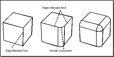
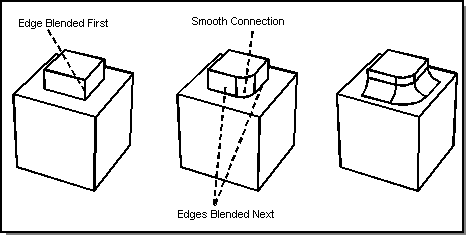
Figure. Smooth Continuity Blends
Mitered Blend
Miter two edges first, which creates a smooth path for blending the third edge. Decrease the radius of the third blend to roll through the miter arc (the arc that is produced by intersecting, or mitering, the two blend surfaces). The following fugure illustrates this.
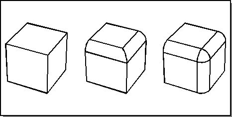
Figure. Mitered Blends
Mixed-Convexity Mitered Blend
A mixed-convexity mitered blend is a blend on multiple edges that do not all have the same convexity, which meet at a common vertex, and which are intended to be mitered. The following figure shows an example of a mixed-convexity mitered blend in which the two concave edges are mitered first to create a smooth path for blending the third, convex, edge. In this example, there is no problem with a ball of the same radius rolling across the outside of the miter arc.
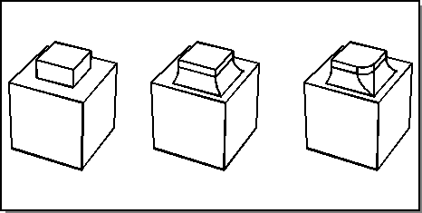
Figure. Mixed-Convexity Mitered Blend
Mixed-convexity mitered blends may not produce a unique valid solution. Therefore, ACIS disallows a single blend to be fixed with mixed-convexity mitered blends. The user must blend the edges separately to specify which solution is desired. In other words, the user must create the blend in multiple steps, blending the edges in the desired order.
The following two figures illustrate that blending edges in different orders can produce different valid solutions. Each figure shows the original body (a small block sitting on a larger block), the result after the first edge is blended, and the final blend solution.
In Figure. First Solution: Blend Concave Edge First, the blend is done by starting with a blend on the concave horizontal edge and then blending the convex vertical edge.
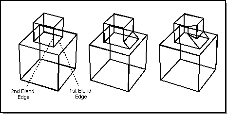
Figure. First Solution: Blend Concave Edge First
In Figure. Second Solution: Blend Convex Edge First, the blend is done by starting with a blend on the convex vertical edge and then blending the concave horizontal edge.
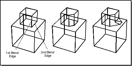
Figure. Second Solution: Blend Convex Edge First
Single Blend
If an edge joins smoothly with any other edges, any blend that is applied to the edge will also automatically be applied to every edge in the smooth sequence. This behavior may be overridden by specifying a single blend. A blend surface will then be calculated for the single edge, and be extended, intersected and capped with nearby faces.
As an example, first miter a pair of edges, then blend the third edge as a single blend to force it to intersect with the existing miter, instead of following the miter arc. The following figure shows an example of a single blend on a miter.
Single blends are not always geometrically possible. This is illustrated in the examples of the previous two figures, if round blends are used in place of chamfers.
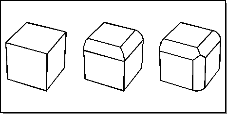
Figure. Single Blend
Simple Vertex Blend
The following figure shows an example of a simple vertex blend. The three edges and the vertex are blended simultaneously with the same radius. A setback is used on this vertex blend.
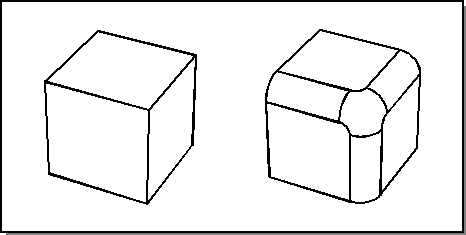
Figure. Vertex Blend with Setback
The following figure also shows a vertex blend, but the edges being blended are of mixed convexity. The three edges and the vertex are blended simultaneously with the same radius. A setback is used on the vertex blend.
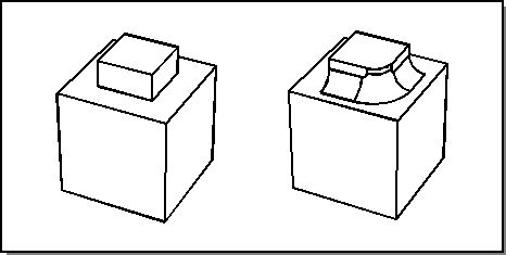
Figure. Mixed-Convexity Vertex Blend
[Top]
© 1989-2007 Spatial Corp., a Dassault Systèmes company. All rights reserved.