Blends on Sheet Bodies
ACIS handles blends on sheet bodies (sheet blends). This allows blending between two surfaces, rather than just blending faces that reside in a solid. A sheet body is a free standing face that may belong to an open solid.
Note: A sheet blend is not the same as a blend sheet. A blend sheet is just a temporary sheet with single-sided faces that is created as part of the blend process on solids. The blend sheet may been seen during single step blending, but it is not part of the completed blend.
Compared to blends on solids, blends on sheet bodies differ only where they meet the sheet boundary. If an open end of a sequence of blended edges lies on the boundary of the sheet, there is no adjacent face available to intersect with the blend surface in order to trim that surface at the open end. However, the end points of the trimming curve are known; these are the points at which the spring curves of the blended edge meet the sheet boundary. The two points are joined with a curve defined in the parameter space of the blend surface.
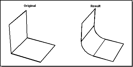
For chamfers, the curve will be a straight line in parameter space. For rounds, the curve is one that at it its ends is tangent to the edges of the sheet at the two points. Special cases where a 3D straight line or circle can be used are recognized. The following figure shows a simple round sheet blend on two double-sided planar sheets.

Figure. Simple Sheet Blend
Where an end point of the joining curve lies at a vertex of the sheet body boundary, the end tangent is not defined, and so a curve is made in parameter space that meets the end point in position only.
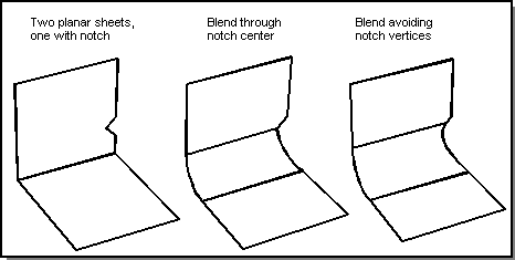
The following figure shows sheet blends in which one of the double-sided planar sheets contains a V-notch. The first sheet blend goes through the center of the notch. The second sheet blend goes through the notch, avoiding the vertices. This is an example of an end point at or away from the sheet boundary vertex.

Figure. Blend Through Notch
The faces being blended must be all single-sided or all double-sided. Blends at non-manifold edges (edges meeting one or more than two faces; for example, an edge of a cellular body where an internal face meets two external faces) are not permitted. Equally, the spring curves of the blend at an end of a sheet blend must not end at non-manifold edges. This rules out blends such as a blend along a swept L-shaped sheet that is built into a solid. Away from the boundary of the sheet, a blend on a sheet body behaves like a blend on a solid, and can contain vertex blends, miters and so on. An error will be signaled if there is an attempt to set a blend on a vertex or edge of a sheet boundary.
Sheet Blends between Disconnected Faces
Standard blending allows blends between sheet faces when there are edges connecting them. Blends between disconnected sheet faces are enabled through entity-entity blends using the Advanced Blending Component.
Complex Sheet Blends
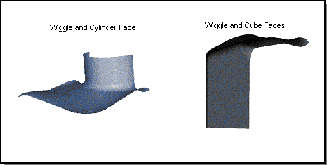
The following figure shows two examples of complex sheet blends. The first is a wiggle blended with part of a cylindrical face. The second is a wiggle blended with two free standing faces, which were originally from a cube.

Figure. Complex Sheet Blends with Wiggles
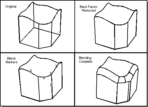
The following figure illustrates a complex sheet blend. This example shows round blends, a vertex blend, and a miter blend in a sheet blend on three faces and a wiggle. The second image in the figure shows that the back faces were removed to create a single-sided sheet. The blends to be completed are marked in the third image of the figure.

Figure. Complex Sheet Blend on a Wiggle
[Top]
© 1989-2007 Spatial Corp., a Dassault Systèmes company. All rights reserved.